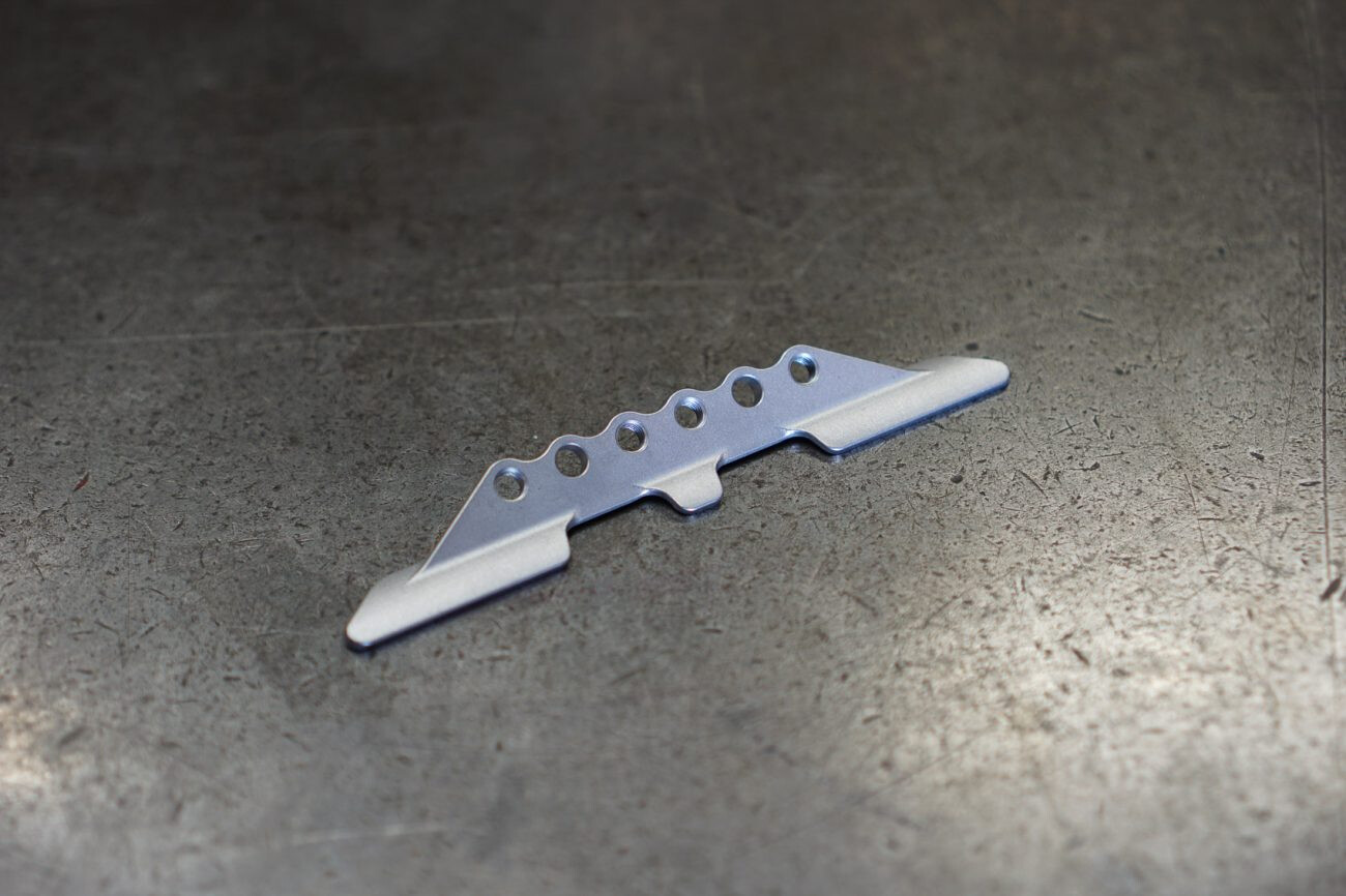
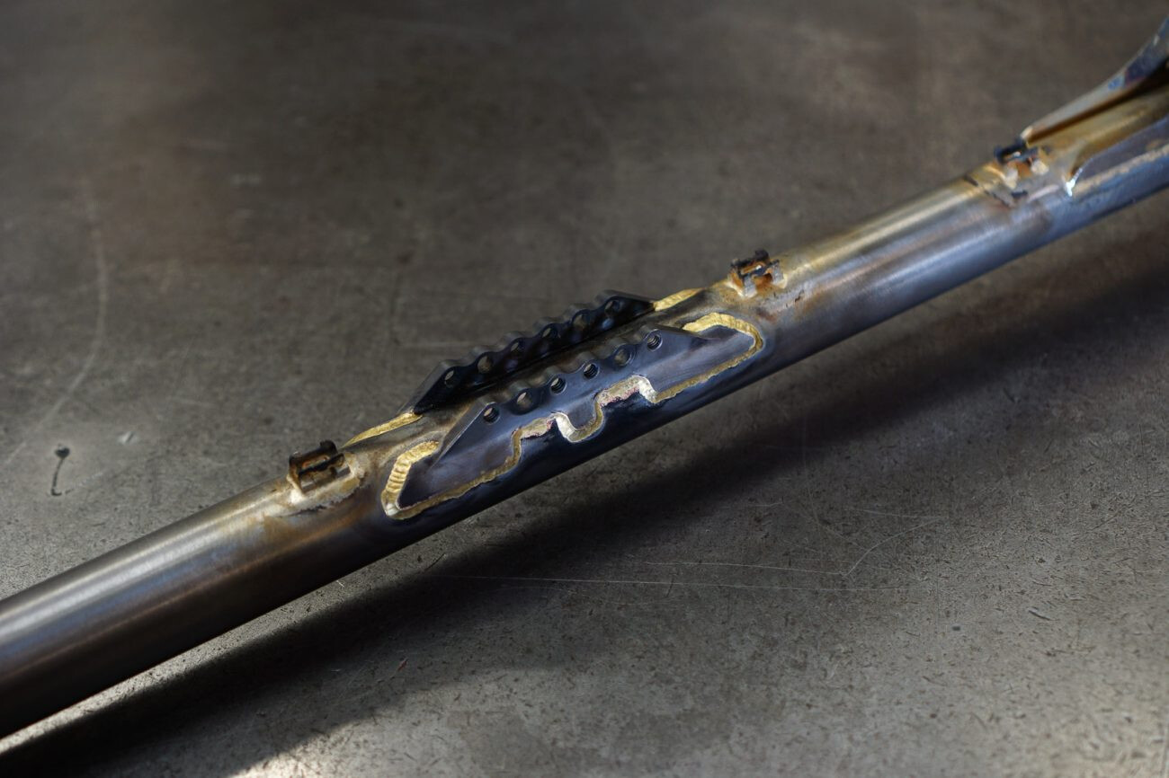
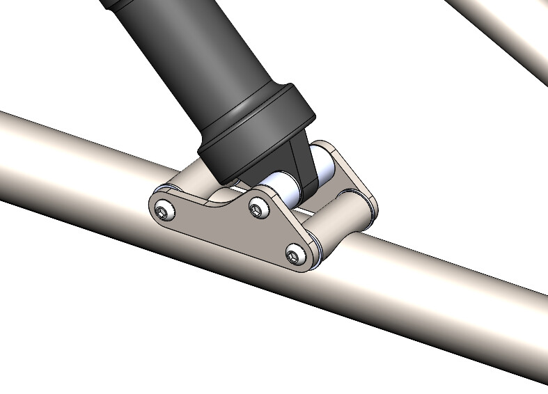
Looks like Starling’s have a custom downtube shock plate. It looks too smooth to be cast and too complicated to be machined. Does anyone have any ideas how it was made? I think it is cast…
This may seem silly but it’s because I hate reaming. I don’t have a machine large enough or strong enough to ream a tube of that width or to that depth. In my experience, hand reaming is very hard, doubly so when using adjustable reamers. By oversizing the seat tube I can machine a collar to hold the seat post. That said, I realize now I could use an oversized butted tube and save some weight so that’s definitely something I will consider.
That’s a very cool looking part. I’m no expert in this but I know v process casting can produce parts with high dimensional accuracy and surface finish compared to sand casting or investment casting. Enough to where a part like that could probably be used without any post processing.
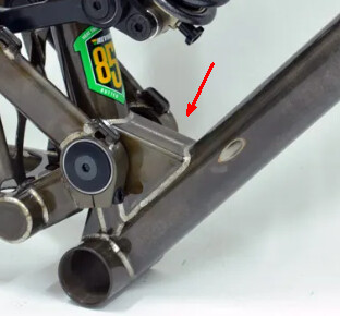
Structurally, I would agree with @Daniel_Y for the seat tube diameter. The load at the main pivot will be pointing forward and down, loading the DT most directly. I would suspect that a gusset between the DT and ST to house the main pivot would be a good idea. Similar to how the BTR Pinner’s were made:
In general terms, I would start with a 1mm straight gauge DT - but this will depend on your intended trail use (XC, trail/enduro, DH)
While not the exactly loading case and direction, a decent barometer is Neko Mulally’s steel DH bike. He mentioned in this video at 2:13 Frameworks Steel In Depth that the DT is 1mm thick straight Reynolds 853 which has a published ultimate tensile strength of 1200 MPa.
That Starling part is trick! From the surface finish and geometry, it looks cast to me. These edges look like the parting line for the mold tool, but tough to say for certain since the part has definitely been cleaned and deburred.
Thanks for posting tubing details. I’m considering similar things so this is good confirmation that I’m on the right track.
It might make for easier connections if the bridge tubes are slightly larger diameter than the seatstays and chainstays. Maybe they could go to .875" (22mm)
I have been considering 1.375"×.049 down tube. Because the jump in wall thickness is greater than what we are used to, the smaller diameter tube is stronger, stiffer and tougher than 1.5×.035 but natually, it is also heavier.
I am not advocating for one over the other but this is an option that I had overlooked until recently. I am trying to balance the increase in tube weight against the potential decrease in gusset weight as well as reduced stress riser possibly and easier construction.
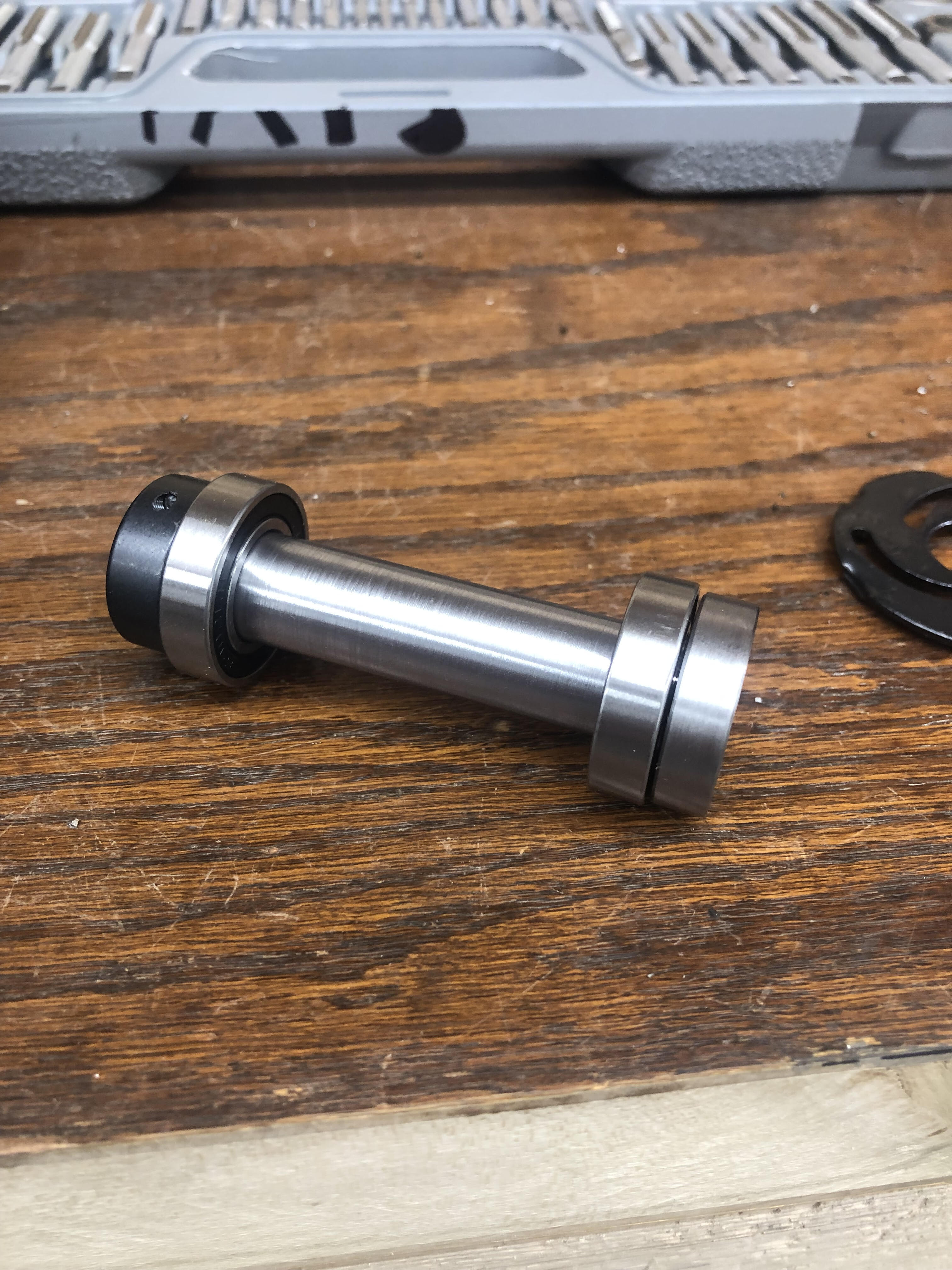
Firstly, I’ve been able to find off the shelf components for the shock bushings and bolts, both upper and lower eyes. I will see if I can find anything that would work well for the lower pivot. There will certainly be some lathe work here and there to make things fit nicely but it will still save me lots of machine time.
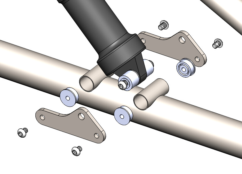
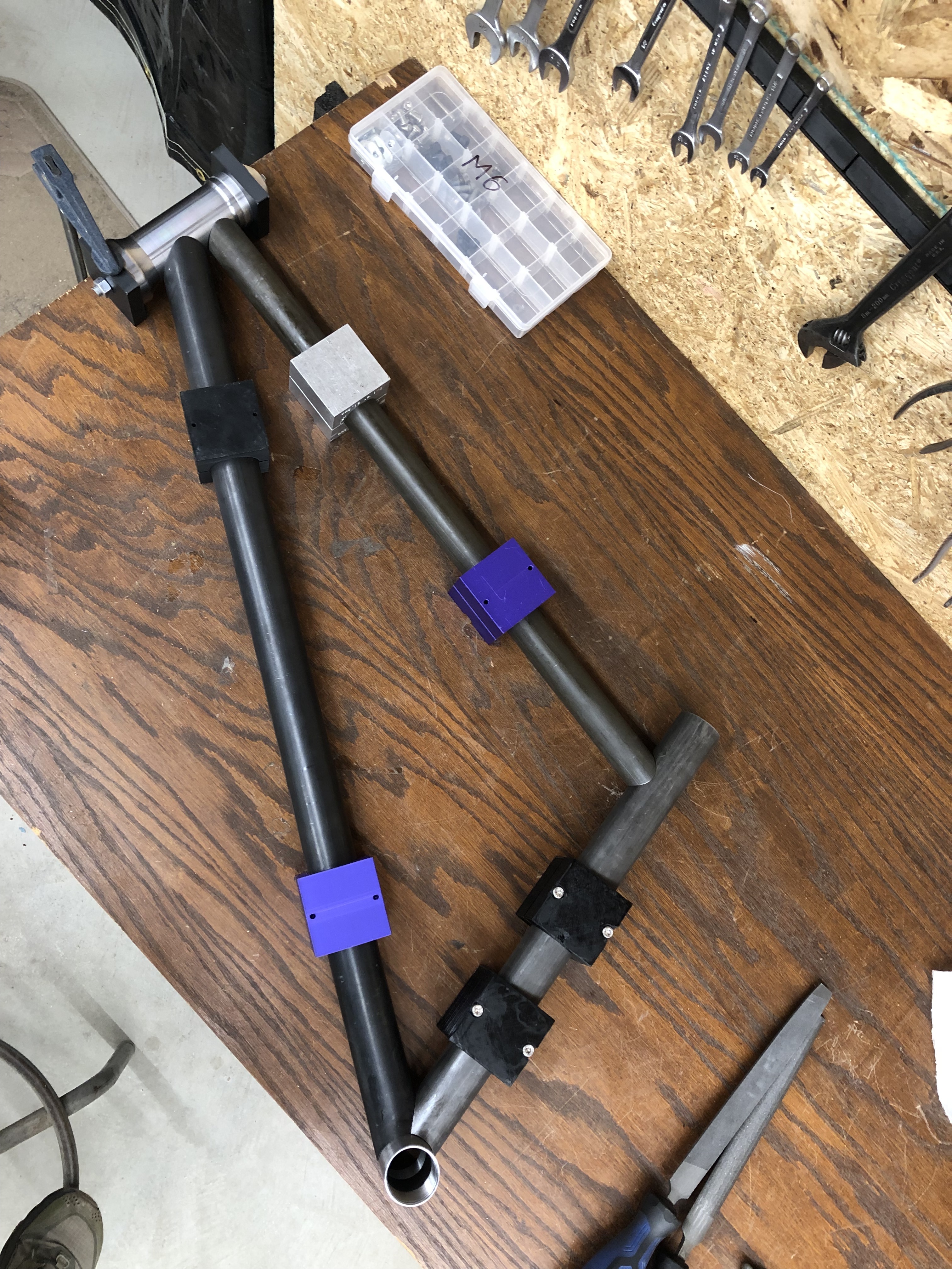
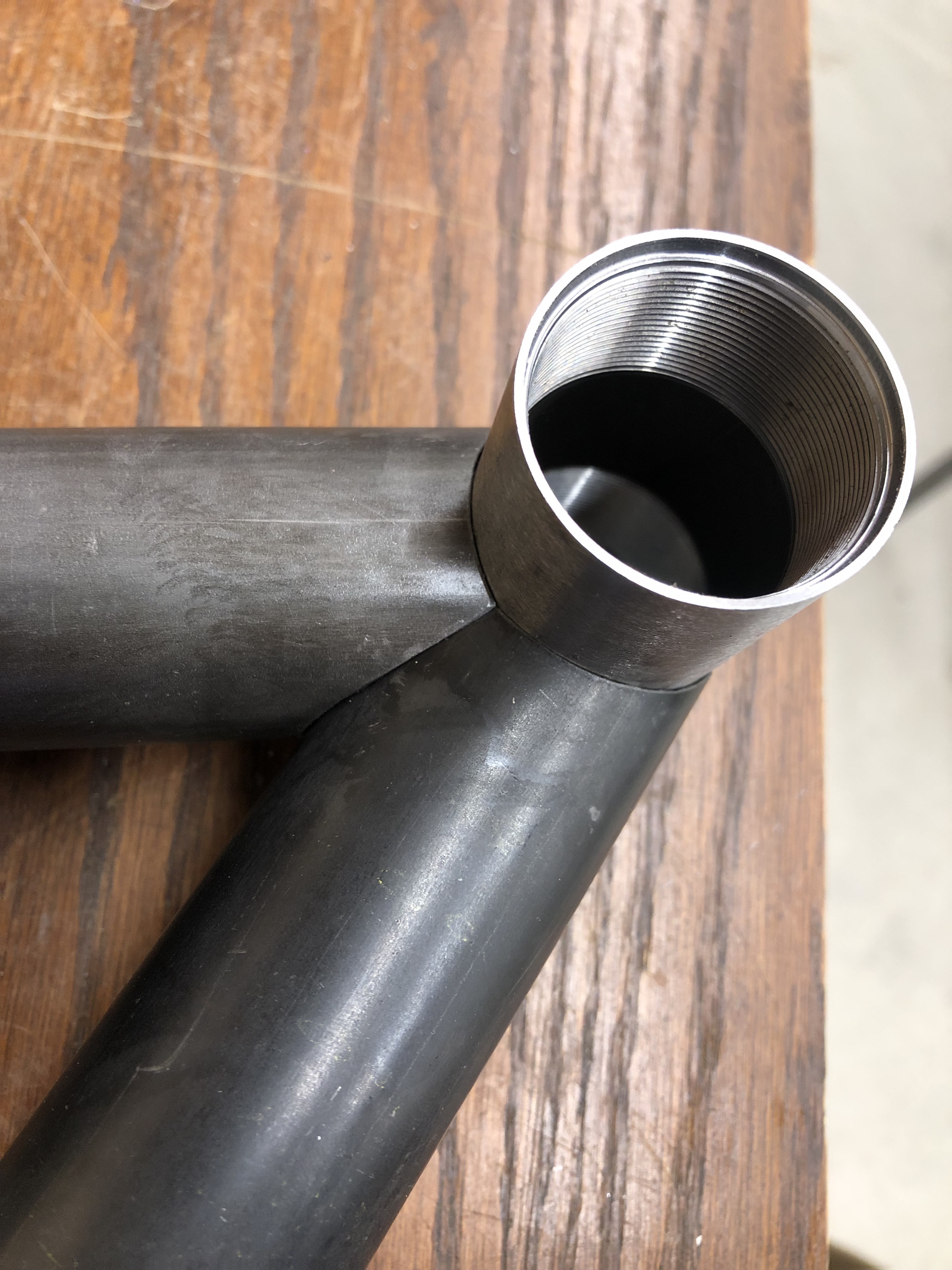
I’ve come up with a different way of mounting shock tabs to the frame. The downtube would be mitred for two (maybe more?) tubes to be brazed in perpendicular to the DT, sort of like the main pivot mount. “cups” could be silver brazed into each end which the shock mount tabs would be bolted to. The CAD shows bolts going into tapped holes in the cups, but I’m leaning toward making them thru holes and having one bolt all the way through since I feel like it would be stronger. My chimp brain doesn’t see why this wouldn’t work. I could make some generous fillets to distribute the force better.
The primary reason for this idea is because I think it would be easier to fixture. I’m thinking I could fully mitre the downtube by itself, then fixture the shock mount tubes, pivot mount tube, and bottom bracket together, ensuring that they are all in line and centered on the DT… Just my thoughts
I have just brazed a pair of plates with holes on either side of the dt then made a pair of flat plate shock mounts. The mount itself was more steel plate tapped for M5 and four bolts hold it together.
So I started the build a couple weeks ago. As planned, I’ve been very meticulous at each step. There’s not a whole lot to say but I do have some pics to share.
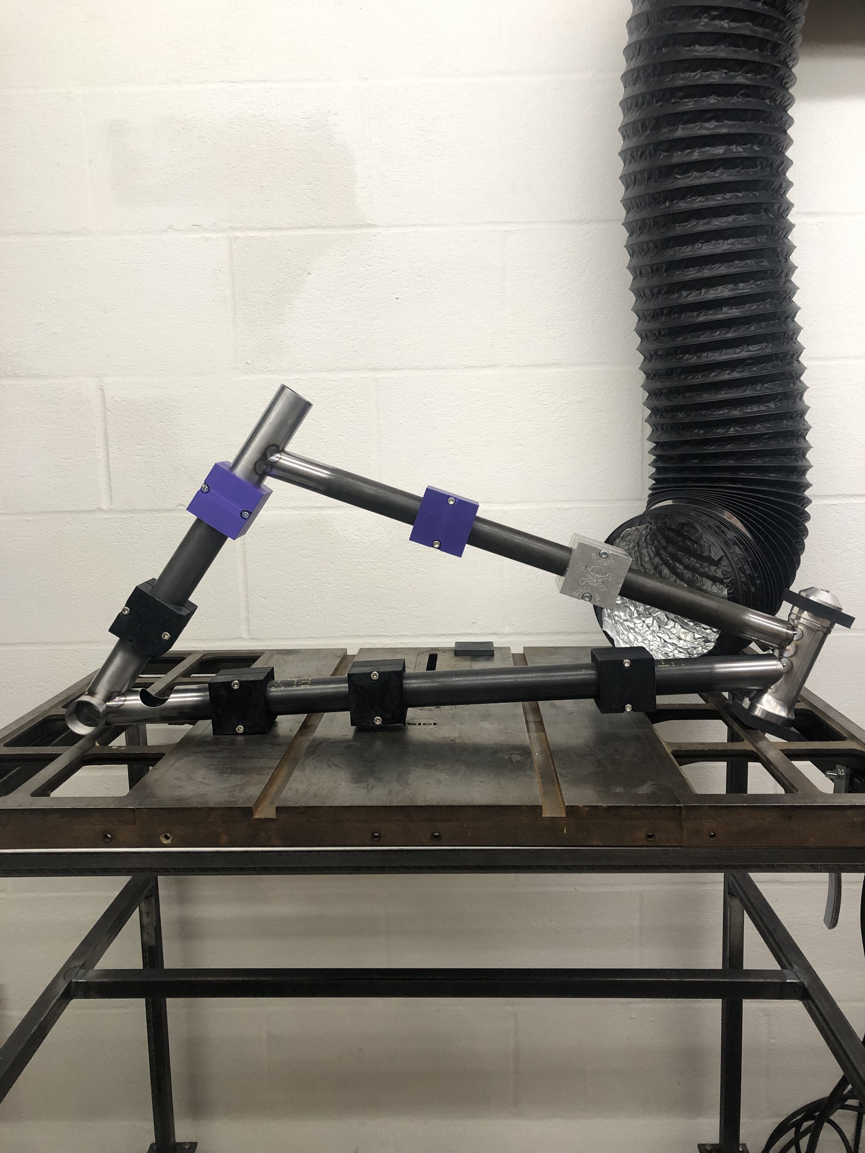
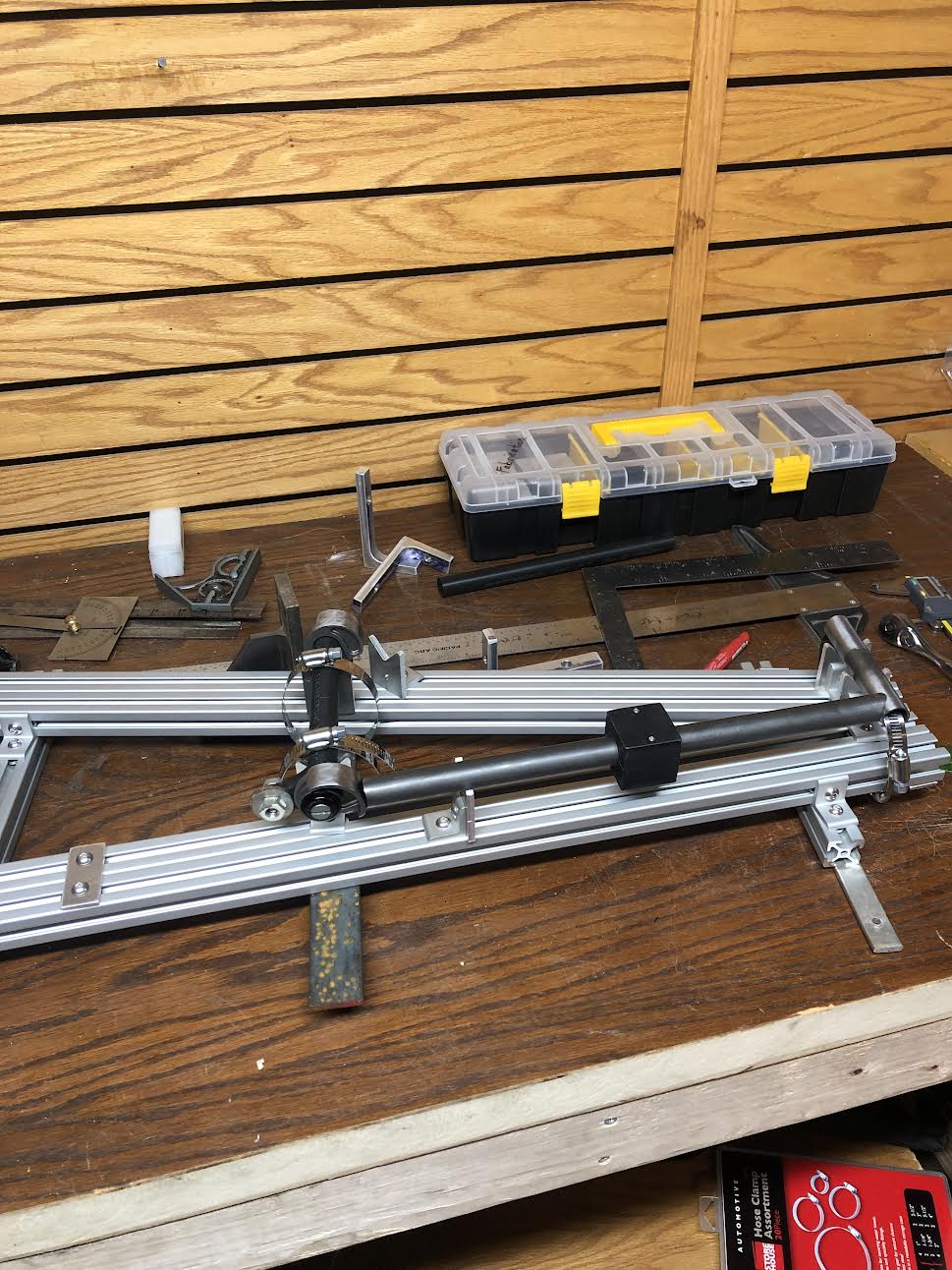
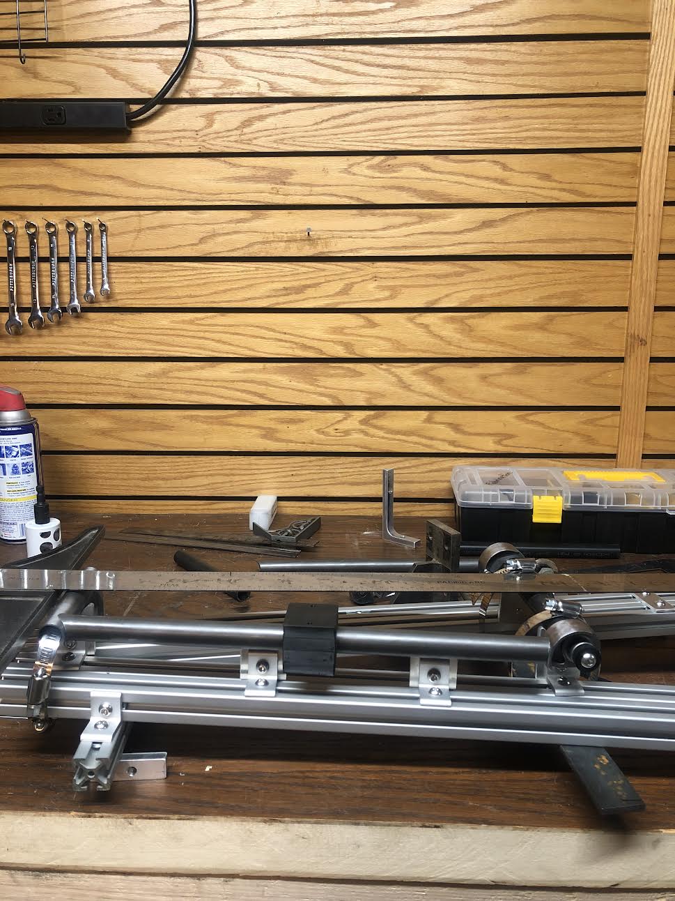
I started by making a jig for the chainstay assembly. I plan to disassemble and re-make a jig for each step, reusing the 80-20 extrusion to save money. I don’t have a good flat table to fixture off of but I think the extrusion alone should be good enough for me.
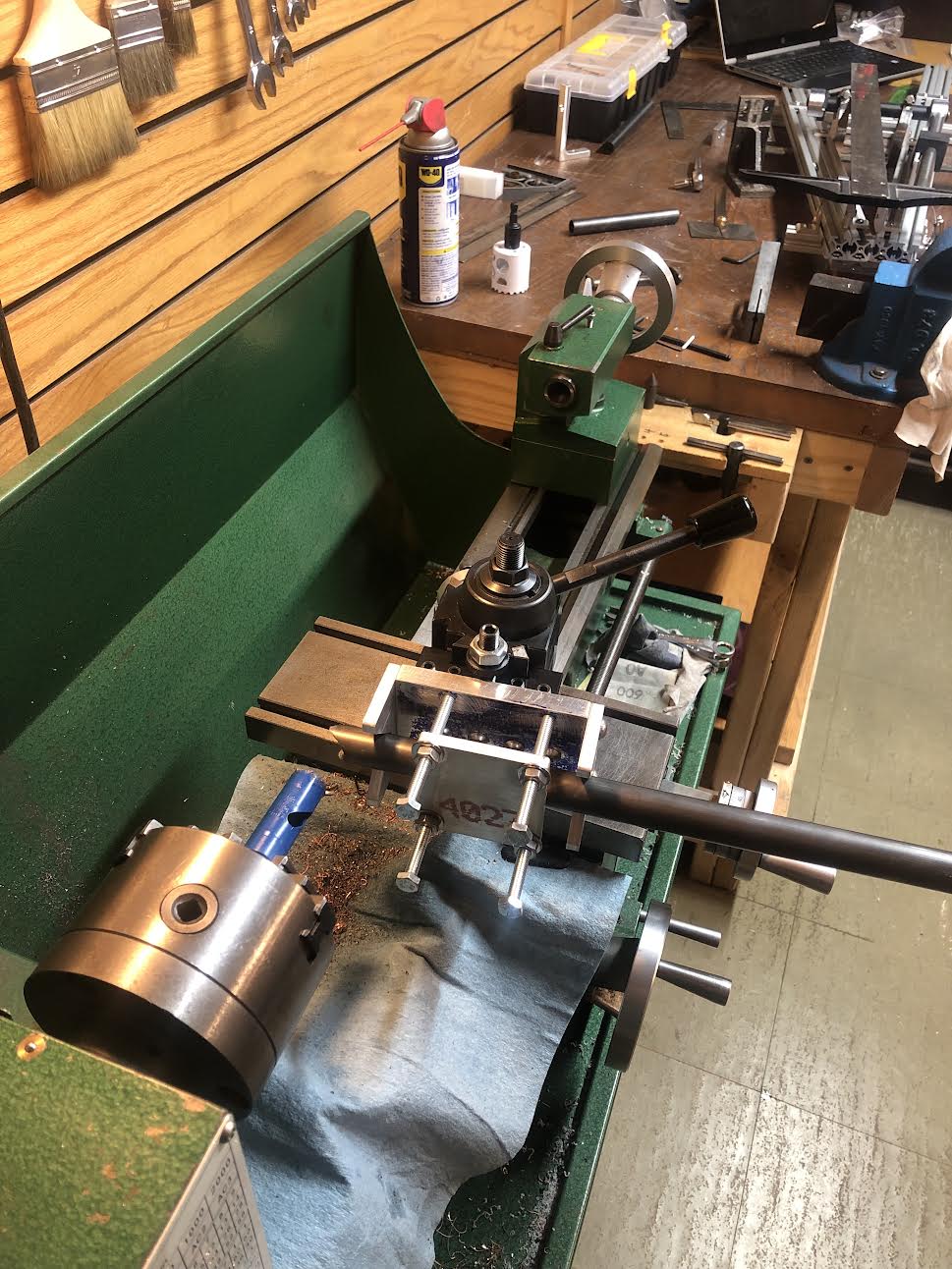
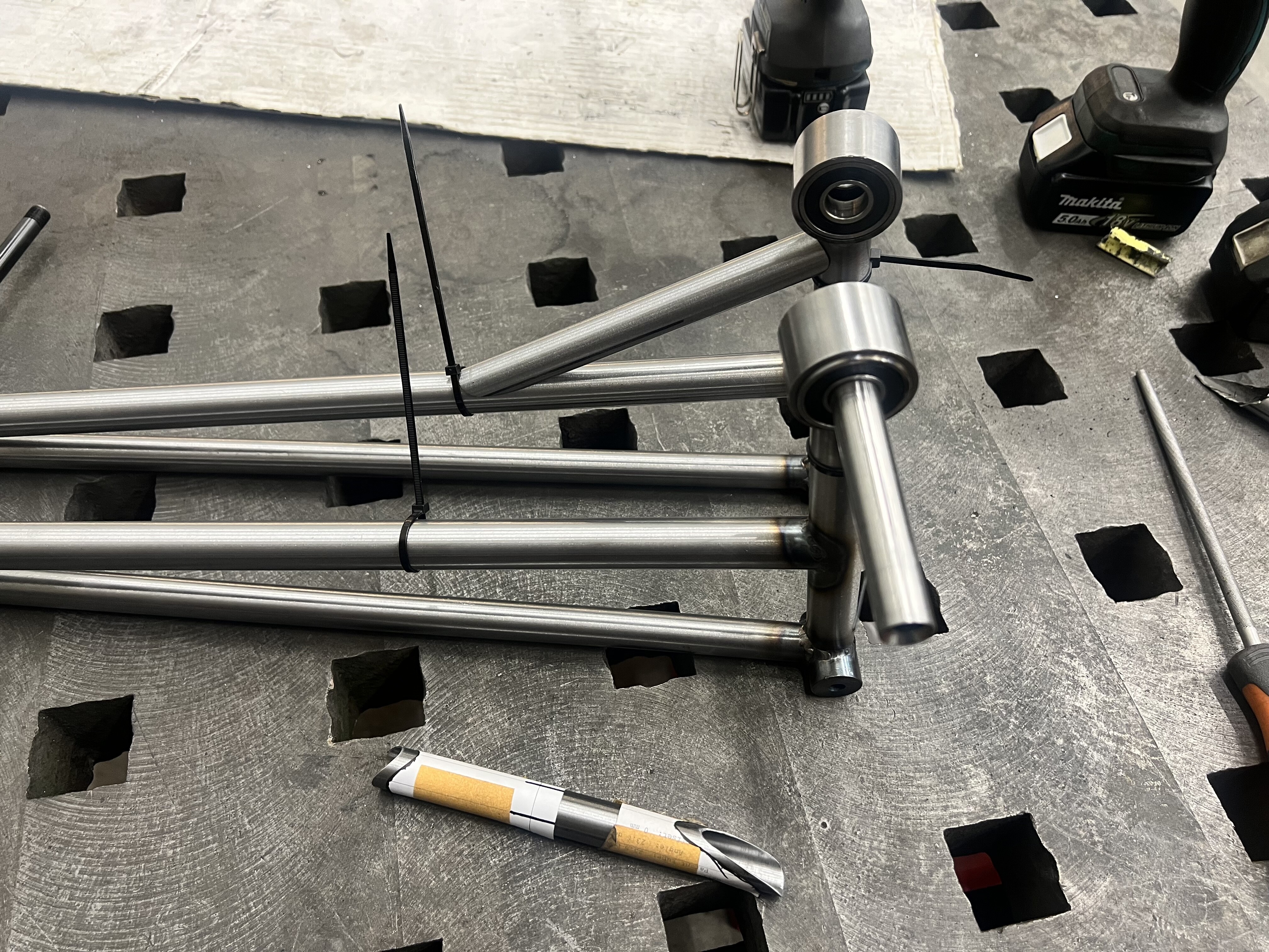
Here’s my humble lathe tube notching setup. It isn’t very rigid but with careful feeding it does the job. Improving the design will be a side project for another day.
One of the most difficult parts of the process so far is measuring. Rectangular stuff has nice flat faces to reference, tubes do not. I used a protractor to find angles between adjacent tubing, and a carpentry square to get things in line. The first time I tacked this subassembly it was too far askew to bend straight and I had to start over. If anyone has any tips for me or knows of any tools I should buy to make my life easier let me know.
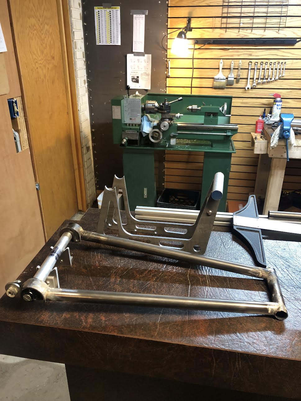
Here’s where things stand now. First subassembly tacked. I plan to tack the whole rear triangle before making my fillets unless someone gives me a good reason not to.
Nice. Probably not much help since I’m a total noob. I take my angles and offsets from fusion and then make paper templates with Metalgeek. You might have to make tube diameters smaller or bigger, depending how accurate your printer is. My home printer is near to 100%, but work printer needs 15% bigger diameter to match my tubes. Cut it out and wrap around the tube - if it wraps exactly around the tube, then it is matching. After that - angle grinder and files are your friend. If a little gap happens somewhere I tap it with a punch. Takes a little longer, but that way I don’t have to make all the tube blocks and buy all the hole saws, I find them wobbly and out of spec, and I always found myself grinding tubes to fit afterwards anyway. Out of the cheap ways I find it working nicely.
I have a long ass caliper that I use to measure. And I have found strings to be very helpful. Also measuring the main frame I used a laser level. oh and lets not forget the digital angle gauge. To my surprise, the frame has been quite straight so far.
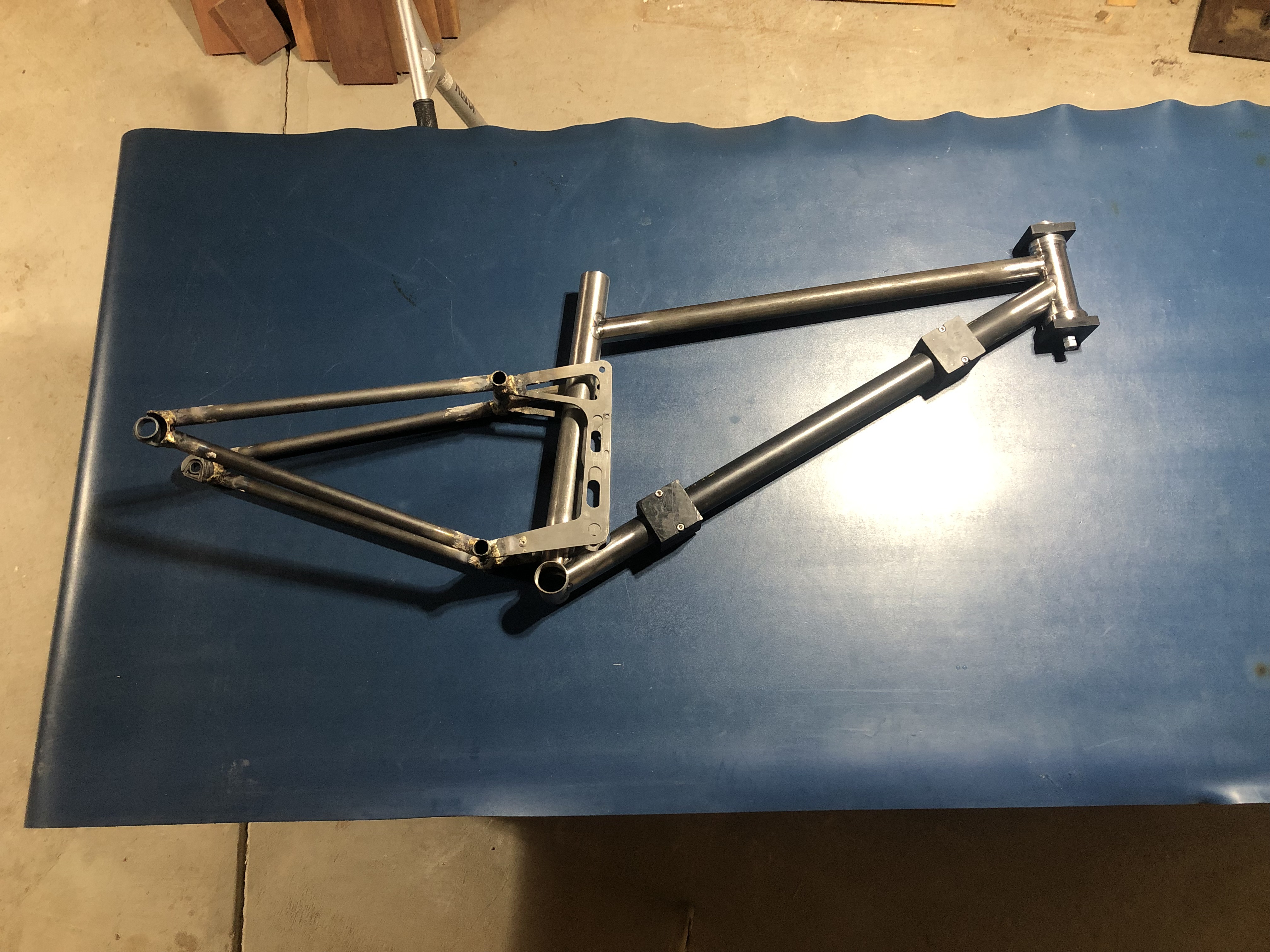
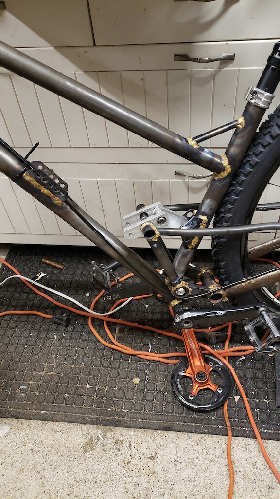
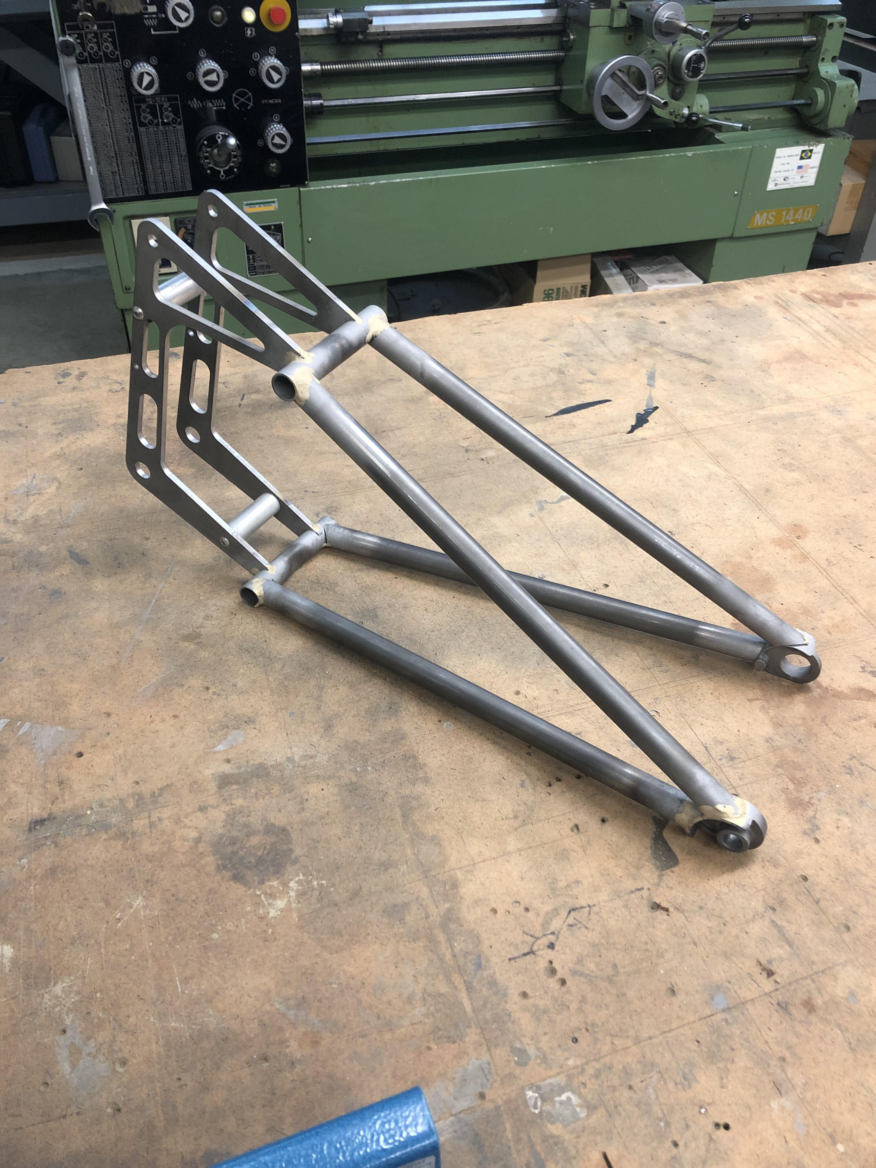
It’s been a long time since I posted but I’m back at it now. Back in December, I finished tacking together the rear triangle and getting it aligned as well as I could. I had a very hard time brazing the thick plates and cast dropouts to the thin tubing and that was frustrating. I ended up taking a break from my bike for a couple months to work on other projects. In that time I also purchased a tig welder, which I hope to use make the rest of the frame. I think brazing is very cool but I think tig is a better tool for me for the things I want to do beyond bike stuff. I still have a couple more months before the trails open up so I’m not feeling urgency to expedite the build yet.
…Anyway, my life story aside, this picture is the rear triangle tacked and ready for the final fillets to be laid. I sandblasted all the old flux and oxidation off so I hope to get nice clear fillets this time. I also plan to preheat the dropouts and the plates with a maap gas torch before I start brazing, which should make things much easier.
It looks like you’ve done the hard parts already: flowing bronze from the massive areas to the thin.I think preheating as you go is a good idea. You will find it easier to lay a fillet now that the initial connection has been made. Heat will flow better between the two parts, but you will still need to focus much of the heat on the plate and dropouts. Gravity is your friend or your enemy, the more you can manipulate this part as you braze it, the better.
Why MAPP gas for pre-heat? Just use the same torch you are brazing with. Hold it a bit further away and work it over a wider area away from where your joint is on the thick part. The thick part will hold heat longer and when it’s ready then you can add heat to the thin part. I also struggle with this same thing, easier for me to type it than actually do it sometimes.
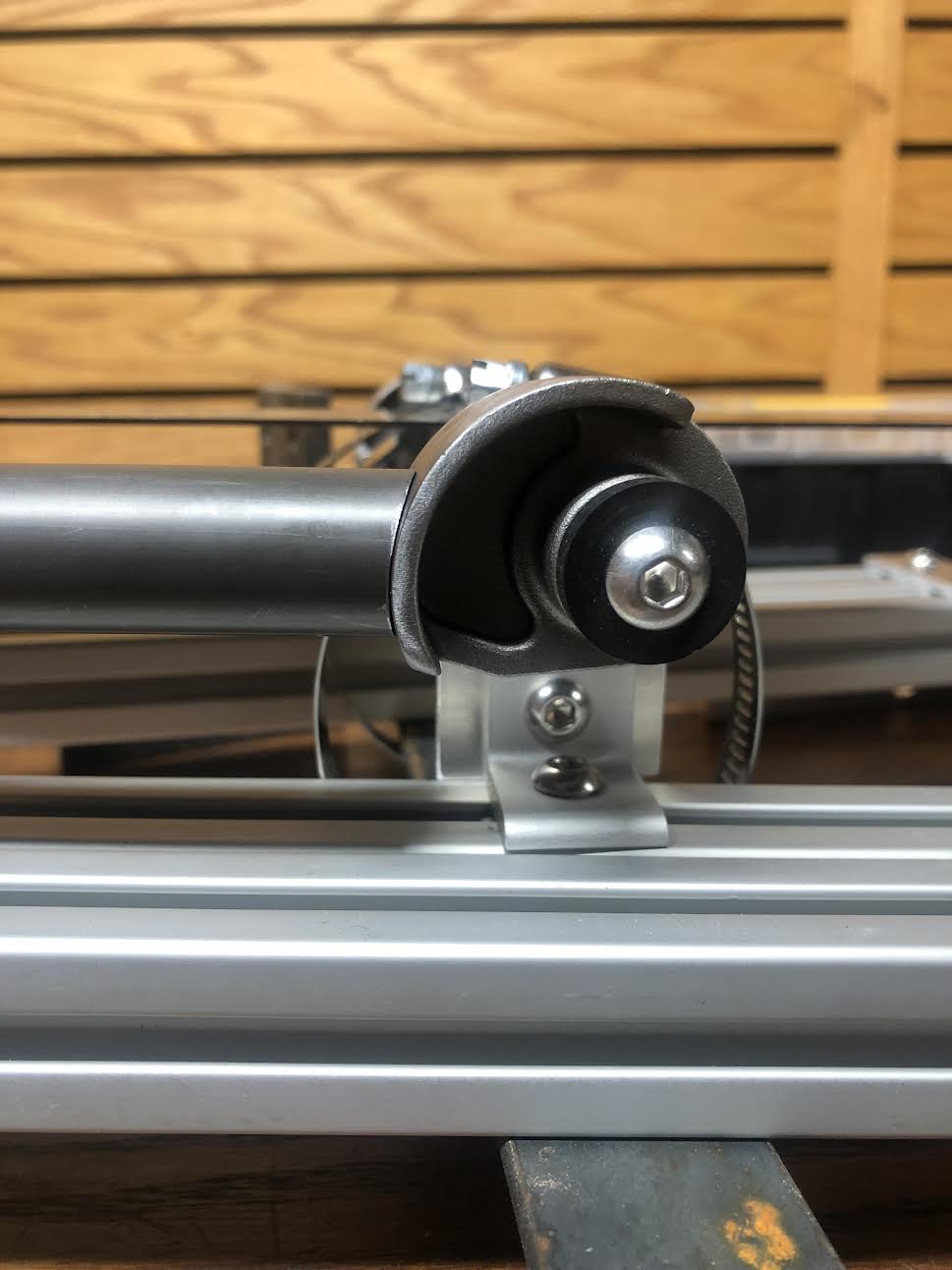
I learned some new things about my lathe tube notching setup. Mainly that I can get a lot more rigidity by positioning the cut location over the carriage (or as close to over the carriage as possible). When the tube sticks out in front of the carriage the cutting force cantilevers the carriage forward if that makes sense. If/when I make a solid tool post for my machine I will take this into account. Also, my machine has no powerfeed setting slow enough, I have to had feed for now but maybe I’ll fix that in the future. This tool is a project all of its own! I’ve enjoyed tinkering with it and improving the system. Next on the list is a better hole saw arbor. But I need to finish this bike before the riding season starts first!
Here’s a to do list for myself…
Front Triangle
Drill vent holes and dropper post cable hole
Tack front triangle
Machine main pivot hardware
Weld and align front triangle
Shock mount tabs
Machine seat tube collar
Gussets?
Braze-ons
Rear Triangle
Finish brazing rear triangle. There’s still a few joints that need more bronze.
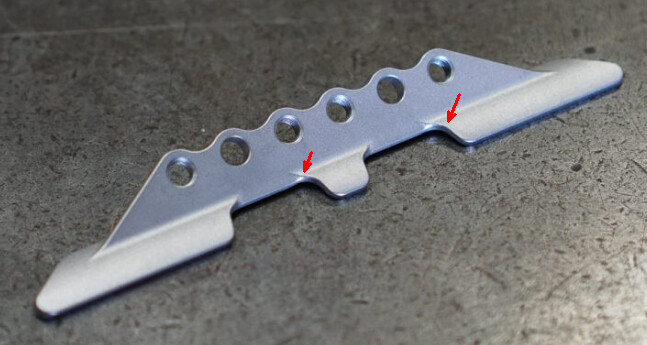
Have you weighed the frame, rear triangle or the plates in the rear triangle? I am the opposite of a weight weenie, but would be interested to know how much mass those plates bring to the build.
The plates are definitely heavy. I haven’t had them on a scale yet but just by hand feel the rear triangle is about as heavy as the front triangle. This will not be a light bike haha.
")