✩░▒▓▆▅▃▂▁ 𝐉𝐌'𝐬 𝐁𝐈𝐊𝐄𝐒 ▁▂▃▅▆▓▒░✩

JM’s Mountain Bike

The thread will serve as a way for me to track my progress, and as a way for the community to give me feedback on my build. Just for some background, this will be my second frame. My first frame was a lugged gravel bike. This bike will be a fillet brazed, single pivot, medium travel trail bike. I’m well aware that this is a big step up in difficulty from my first project and I will try to be realistic and meticulous as I design/build. I’m very much a novice at bike design and fabrication and I welcome any criticism or suggestions for any step of this project.

The design so far…

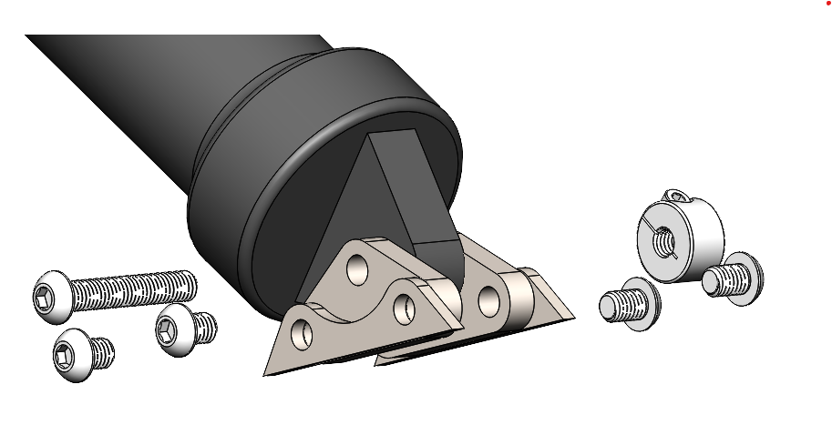
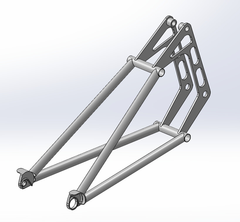
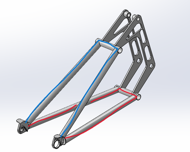
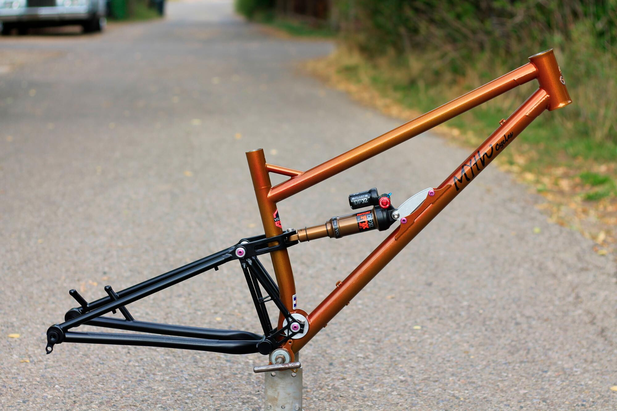
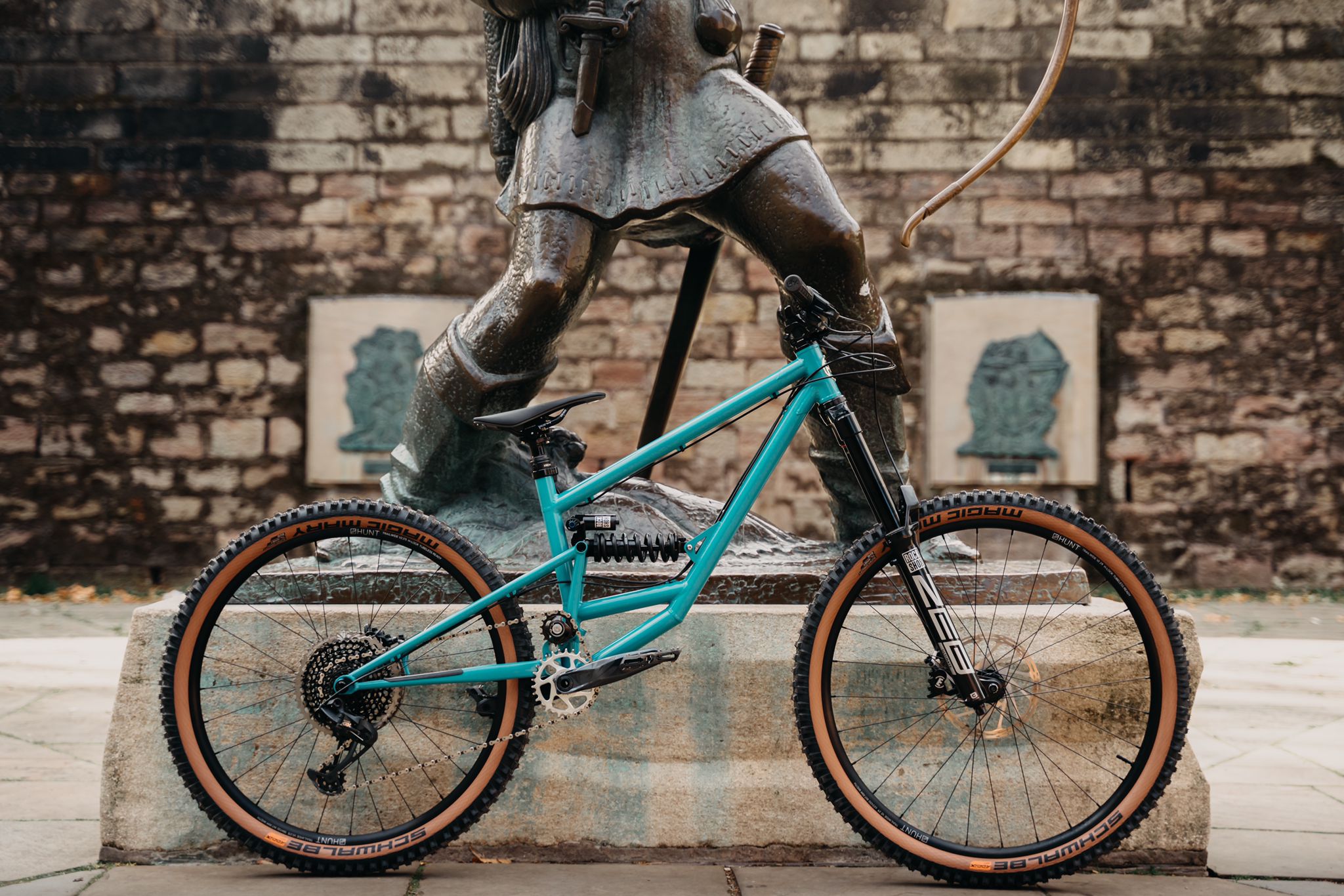
Here’s a full model that uses lots of neat stuff I nabbed from GrabCad. It’s useful for checking clearances and it’s fun to look at. But let’s look at the business side of things.

lev ratio

anti squat

anti rise

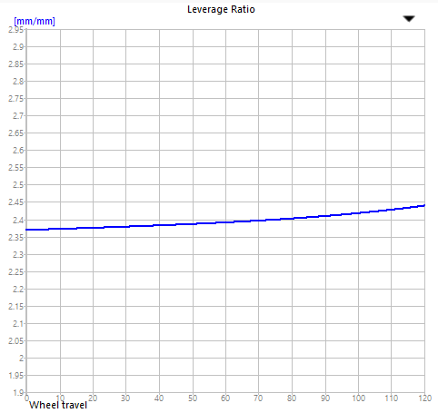
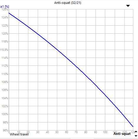
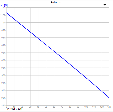
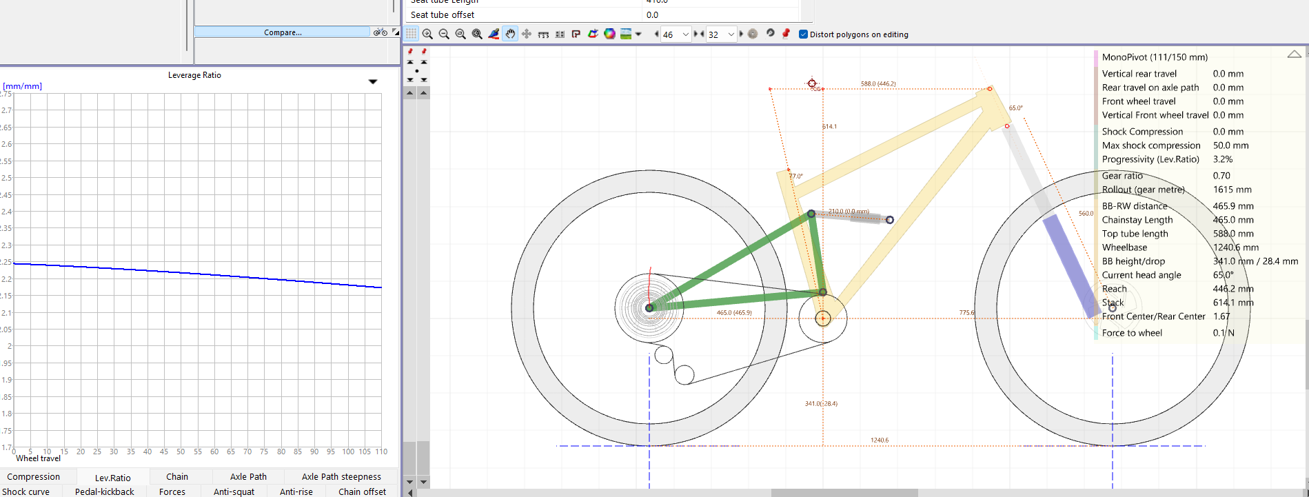
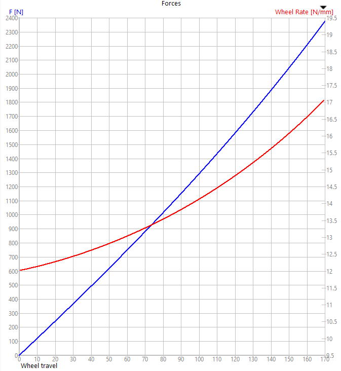
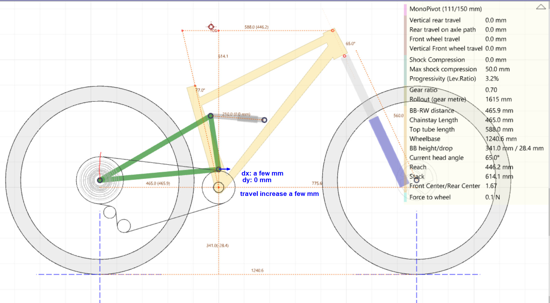
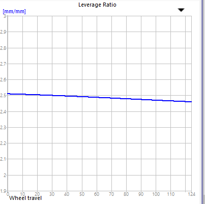
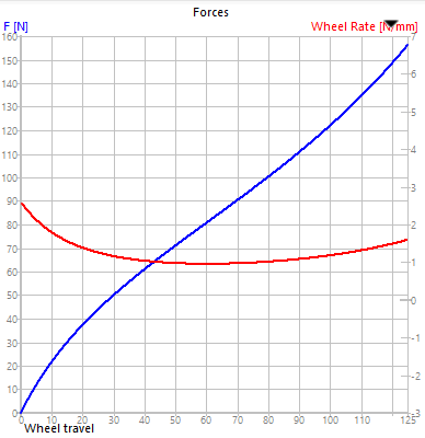
I’m not going for anything revolutionary or super weird. I am aiming for a pretty standard trail bike geo with a linear lev ratio curve. I want something that can climb reasonably, and can hog down descents over hardpack or rocks. I do not do much jumping, and I’m not too concerned about speed on flat ground or climbs. I think I’ll call this bike the “Hog”, since I want it to root through trails like a hog looking for truffles, and also because it’ll probably be heavy. The geo is based on bikes that I’ve owned/ridden and some of the modern trends of long and slack bikes. I may make changes to this as I learn more about bike geometry and I’m open to suggestions on how to improve the bike on this front.

I should also mention the components:

Fork: Fox 34 [150mm travel, 565 axle 2 crown, 51 offset]
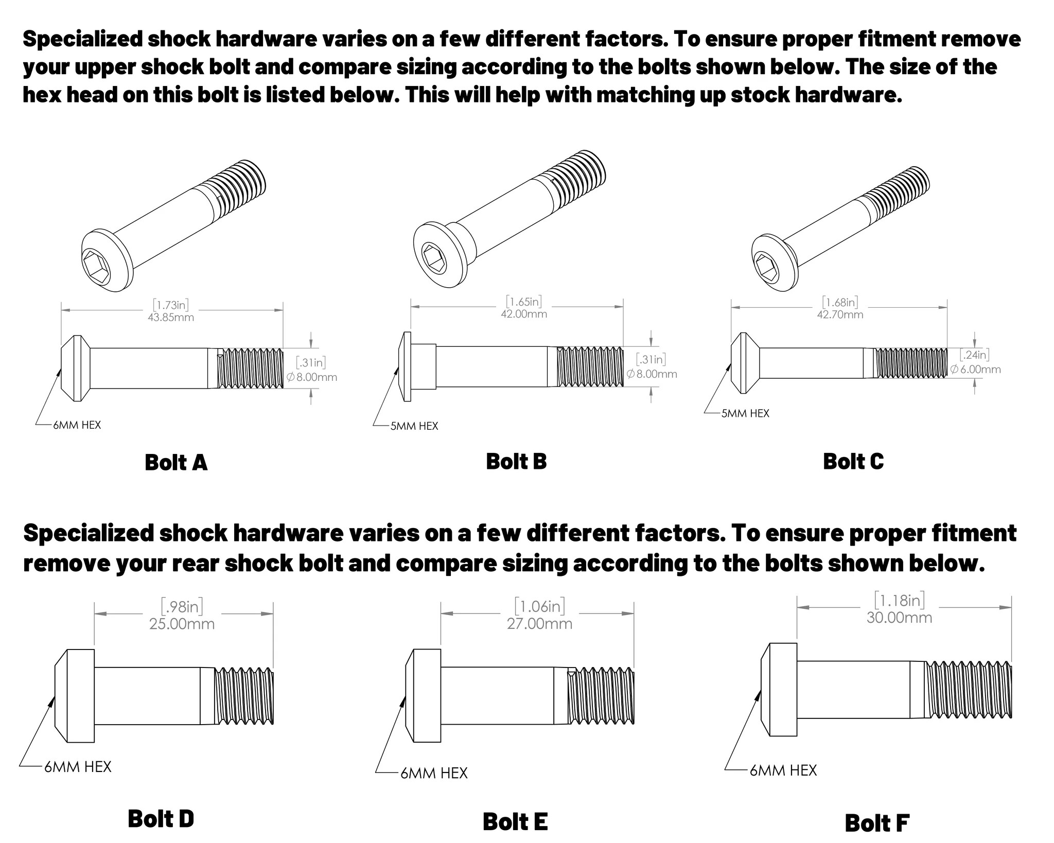
Shock: Fox air shock [200mm eye to eye]
Wheels n tires: 29 x 2.35 tires. 148 x 15 rear axle
Drive: 1x11 shimano, 175mm cranks, bsa BB
Seatpost: 35mm wide dropper
I think that’s all that matters for now…

2 Likes

My second bike was a full squish so I am sure you can do it too. Design looks good to me, geo is very similar to my wife’s bike and its a real ripper. Here’s things I would be looking at:

-Maybe check the antisquat in other gears to make sure you are still over 100% or close to it at sag. Also make sure the CG is around where your belly button would be when seated pedalling
-I would use a metric shock 210*50/55 for this application. Imperial sizing is pretty much obsolete and much harder to find. If you already have/really like the 7.875"/200mm standard maybe consider a intermediary mount so you can change to a 210mm if you ever have need.
-I would be trying to get a bit more progression out of the bike, if the shock tilts the other direction you can probably get about 5% or so. Just drag the points around a bit and see if you can get the leverage curve to invert

If you make no changes at all I think you will still have a fun bike regardless, I look forward to seeing what you make!

1 Like

The Rear Traingle

I’m gonna get ahead of this. It’s pretty funky looking, and if it this design turns out to have major flaws I’d like to figure it out. (also ignore the dropouts for now, I just stuck them in there)

The design hinges (pun intended) around two pieces of 3/16" plate steel that I would get plasma cut. This is primarily to make the fixturing/fabrication of the rear triangle as simple as possible. Fixturing the rear triangle on my first frame was one of the most difficult parts of the process for me.

rear triangle paint

The tubed sections are broken down into two “2D” subassemblies, shown in the blue and red above. They can be brazed together first, then the whole thing can be fixtured and combined.

This design also eliminates the need for a yolk on the chainstay or any sharp bends. The cs/ss might not need to be bent at all. And lastly, the plates also ensure that I have “perfect” spacing between my main pivot and shock eye.

Also I think it looks cool.

Negatives…

It will definitely be heavier than just tubes. The rear triangle might end up being 3+ lbs, I’ve decided I’m okay with that. There’s also the question of strength. I imagine the two plates will be more flexible laterally, but very stiff up and down. Here are some simple static FEAs I did.


500 lbs upward on axle


100 lbs sideways on axle

As expected, there is stress concentration where the plate joins the tube, however, there’s nothing I see that’s alarming otherwise. Increasing tube diameter, plate thickness, or adding bracing somewhere is always an option if I decide I need more strength.

A final negative, which may be trivial, is that there is not a smooth line along the cs/ss, but instead a sharp 90 degree jutting out tube. I believe it is still narrow enough that it will not interfere with my legs pedaling, but if I crash, maybe it’ll bite me?..

As for mounting to the front triangle and bearings and stuff, I have some ideas. I will make a post about that another day.

2 Likes

Thanks for the input.

  • antisquat is still around 115% in the lowest gear at 20% sag so we’re good there
  • I wasn’t sure how to use CG in linkage so that is very helpful.
  • Yes, it is a shock I already have. I plan on making an intermediary mount from front triangle to shock so I should be able to change it in the future.
  • I will give this a try and see how it looks!
2 Likes

Love it, Im attempting something similar.
Not knowing how much you weight and what kind of riding you end up doing. If you are not the lightest I suggest something stiffer than fox 34 and a shock with a piggy back. Please update and of course lots of pictures.
Edit: for simulation you can get some idea from this article Pole Voima eMTB Passes EFBE TRI-TEST Gravity Cat-5 - Pinkbike

1 Like

Very impressive CAD! You even have the siping on the Maxxis Minions :rofl:

I agree with your concerns about the plates being flexy, concentrating stress, and looking a bit weird. However, I always have to remind myself that the first time is never perfect, and that I can’t wait until everything is prefect before I do it.

The design looks good to me. I think the 3/16 plates should be strong enough. I would consider adding a bend to the plates, and directly connecting the CS to the plate. That should make the plate quite a bit shorter and more rigid:

Or, you can bend the CS inwards to clear the chainring, like on the Myth Zodiac:

3 Likes

My second frame as also a single pivot fs frame, jump in and make it happen.

On the flat plates there is a builder called TOR that has done similar.

https://www.instagram.com/p/BvC55a6AFm2/?hl=en&img_index=1

You might get some ideas from his to refine yours.

4 Likes

Pretty excited to see more builders taking on full suspension projects!

Geometry and kinematics look like solid starting places. Very well set up to make a fun bike.

Two points that could help you out in the design work:

  1. Clearances through travel
    Check to make sure there is clearance between components throughout travel. At least at top-out and bottom-out. For more complex linkage designs, checking at sag doesn’t hurt either.

I aim for these values:

  • SS bridge to ST, 10mm min
  • 5mm between suspension components
  1. FEA
  • Adding fillets to the tubing/plate interfaces will improve the hot spots and give a more real-world result.

  • Using a remote load for the rear axle and splitting the pivot bores (adds directionality to your constraints) will also give better results. I would ditch the dummy axle and apply the remote load to the axle bores.

3 Likes

I did not make the components, they are from grabcad but whoever made them did a great job!

This is a good idea, I will have to see how much more this would add to the cost of the plates. I’m planning on using send cut send for this part and I belive they do bending as well.

This is very helpful and I’ll check to see if I have this clearance

4 Likes

I’ve taken the suggestions here to heart and have been playing with my design.

Firstly, I believe the shock I have is actually a 210 metric, I just didn’t measure it right the first time. Glad I double checked.

By adjusting shock angle, I’m able to eek out some progression, but at the cost of suspension travel. I’d be going from 130 to 110 which is a little more than I’m willing to give up. If I used a bent down tube I’d be able to tuck the shock lower down while maintaining the angle, thus keeping the progression while increasing travel. However, bending larger diameter tubes adds a new process to the build that I don’t think I’m willing to take on at the moment. If the design requires, I’m sure I can find some ways to increase room in the front triangle.

I haven’t been able to find much actual numbers on the progression of air shocks but I’m wondering if my use of an air shock (with the possible addition of volume spacers) could compensate for a linear or slightly regressive lev ratio curve. I’m curious to hear your opinions on this. I wanted a relatively linear suspension feel anyway.

1 Like

Depending on the radius of the bend and how many degrees you’re after, BFS can do a bent straight gauge tube for you.

1 Like

I see you have a 50mm stroke on the shock. Most manufacturers just pop a spacer in to reduce the travel from 55mm to 50. maybe just check under the air can and see if it has a 5mm spacer. If it does then you can remove it and you will be at 126mm-ish if that sounds close enough.

Something I tend to look at in Linkage is the forces chart. Set the shock to a linear coil rate (the sag calculator is pretty accurate IME) and it will tell you how many Newtons of force to move the wheel a mm at a given travel. I actually think it it telling of how misleading measuring suspension progressivity in % increase of leverage ratio is.

Here’s my high pivot bike’s chart with 550lb spring:

12N/mm to 17N/mm at bottom out. Thats almost 50% increase in force, but the leverage ratio would describe it as 11% progressive. This is probably actually far more useful once you have a bike with known kinematics and spring rate but this is how I design my bikes now that I have a baseline.
I think I might have gone on a tangent, but hopefully thats helpful.

5 Likes

When I made this one we ended up with a slightly rising-rate leverage curve because I lowered the main pivot at the last minute (meaning a little less room for the shock). I wanted to see how a ‘mid pivot’ would ride.

Anyway, I found the suspension rode amazingly well despite the lack of progression in the leverage curve. And I’m now less concerned about it in general.

I do still think that a little progression (falling rate) is a good thing but it’s not necessarily as important as I once believed. I reckon the shape of the curve is at least as important and probably more so.
i.e the less funny business, the better (for matching a shock tune, ease of tuning on the trail and mid stroke support). But that’s easy to achieve with a single pivot design.

My suggestion would be to not stress too much about the progression and just put the front shock mount where it needs to go within the parameters of the overall frame design. Don’t over complicate it. There’s a brand that appears to do quite well with this model over here.

5 Likes

I have been told many times to ditch the yoke idea, especially when using air shock. This is probably what I’m going to do and make second one with a yoke. That means slightly regressive for my build. Many of the british single pivot bikes are regressive and people love them.

3 Likes

Like @Pi_bikes mentioned - playing with the shock stroke will help increase the rear travel value again.
With the single pivot layout, you could tweak the main pivot X-coordinate forward to increase travel a few mm without too much effect on the anti-squat value (line).

The force graph is a great one to look at to understand how the bike will feel on trail. This is the wheel rate of the bike and is arguably far more important than the leverage ratio because it describes the linkage/shock interaction as a system.
I do tend to ignore the red ‘wheel rate N/mm’ that Linkage gives. Maybe it’s the rate of the rate? Anyone use this in a meaningful way?

The blue force line graph represents wheel rate as defined, N/mm: Y-axis Newtons, X-axis mm of wheel travel.

There is a lot of merit to designing the leverage curve around a certain shock to achieve a desired wheel rate (travel feel). As @Robertt mentioned, pairing a progressive air shock with a regressive leverage rate to have a linear wheel rate will produce a very predictable (intuitive) handling bike through the whole travel.
Pairing that same regressive rate with a coil (linear) shock would result in a wheel rate closer to the shape of the leverage rate (soft off the top, wallowing in the middle, blow through travel at the end). All the opposite of how we’d like a bike to ride.

3 Likes

I’m back with some design changes.

I played a little more with shock position and I moved the main pivot forward. I now have a small amount of progression and 125mm of travel.

image

image

I may make some more tweaks to the geo later, but perfection is the enemy of progress and there is more to be done. such as

Pivots


I know this exploded view is an incomplete mess so I’ll break it down.

Main Pivot


The red lines here represent the rear triangle. A slice of 1-1/8" headtube stock will be brazed onto the downtube. I will then press cups in that capture bearings (6902 sealed bearings is what I plan to use). The cups will bear on the outer race, and on the other side a washer will bear on the inner race. Then there is the rear triangle. Then a pivot axle secured with a threaded shaft collar to let me adjust the preload.

I would make the pivot axle, washers and cups on a lathe and buy the rest of the components.
The axle and cups would be steel and the washers would be aluminum.

Lower Shock Eye

I was thinking of using Delrin bushings for the lower shock eye. One bushing within the eye of the shock, and two on either side against the rear triangle. Same sort of axle + threaded shaft collar as the main pivot.

It’s worth nothing that the rear triangle at this pivot would have
theseimage 
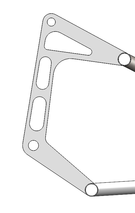
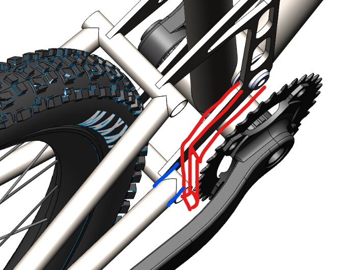
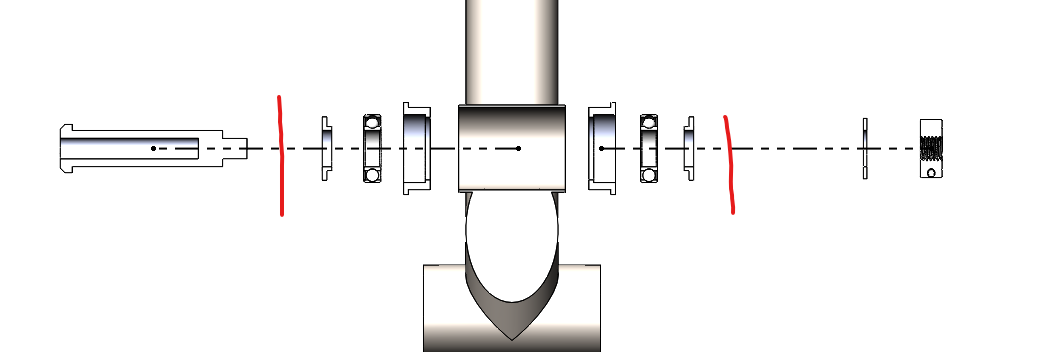
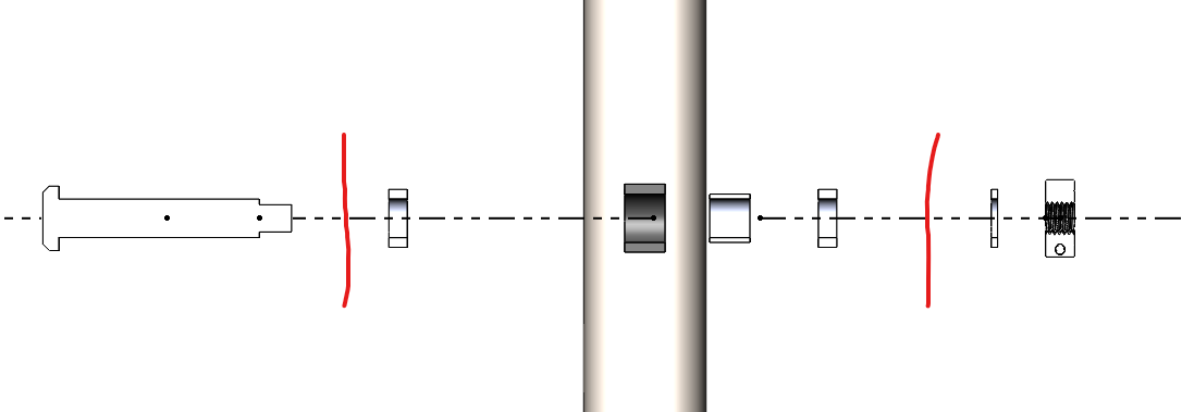
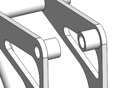
brazed into the plate for strength since… they’re further away?.. idk how to explain it but maybe you can understand.

Upper Shock Eye

This is the simplest. There’s very little rotation at all here. I think it would just be a bushing within the eye of the shock, flanked by the two plates that secure it to the frame. Despite what this model shows, I would use an axle with a smooth bushing surface rather than a normal screw. I’m not sure if the shaft collar is even necessary. A regular nut might be just fine here.

Let me know what you think. A big goal here is to simplify the manufacturing process as much as possible.

6 Likes

Looks good

3 Likes

It could be useful to steal some pivot hardware from a full suspension. There is plenty of suspension hardware repair kits floating around that may have what you need.

For example:

I love the threaded locking collar on the main pivot but it might be overkill on the shock eyelet. The rotation and forces are much lower on the shock eyelet.

3 Likes

This is a good idea. In fact, Coincidentally I’m stealing the components from a stumpjumper. I should look over the pivot hardware on that bike to see how much more I could steal.

That’s what I was thinking as well. Glad to get some comfirmation.

1 Like

Materials

I’m closing in on materials. I want to use mostly 4130 straight gauge tubing for the sake of simplicity. I will make a collar to capture the seatpost, eliminating the need for a bike specific seat tube. The seatstay and chainstay bridges are a thicker wall since they join with the plate as shown above.

There’s still one part I’m unsure of and that’s the downtube. The downtube is the anchor for the suspension in this design and I wonder if I should consider using a thicker wall. I know that standard is to have reinforcment where the shock tabs are mounted in the form of a sleeve pressed on. If I increased the wall thickness could I avoid this step? or would the required thickness add too much weight to consider?

Headtube: 110mm tapered for integrated bearings
Downtube: 38.1mm OD, .89 wall [1.5" OD, .035" wall] ???
edit: I have decided to go with this wall thickness
Toptube: 31.8mm OD, .89 wall [1.25" OD, .035" wall]
Seattube: 38.1mm OD, .89 wall [1.5" OD, .035" wall]
Seat+chainstays: 19mm OD, .89 wall [.75" OD, .035" wall]
Bridges: 19mm OD, 1.24 wall [.75" OD, .049" wall]
Bottom Bracket: BSA
Dropouts: SRAM UDH
Brake tab: ISO tab
Shock mounting tabs: .125" 4130 plate

3 Likes