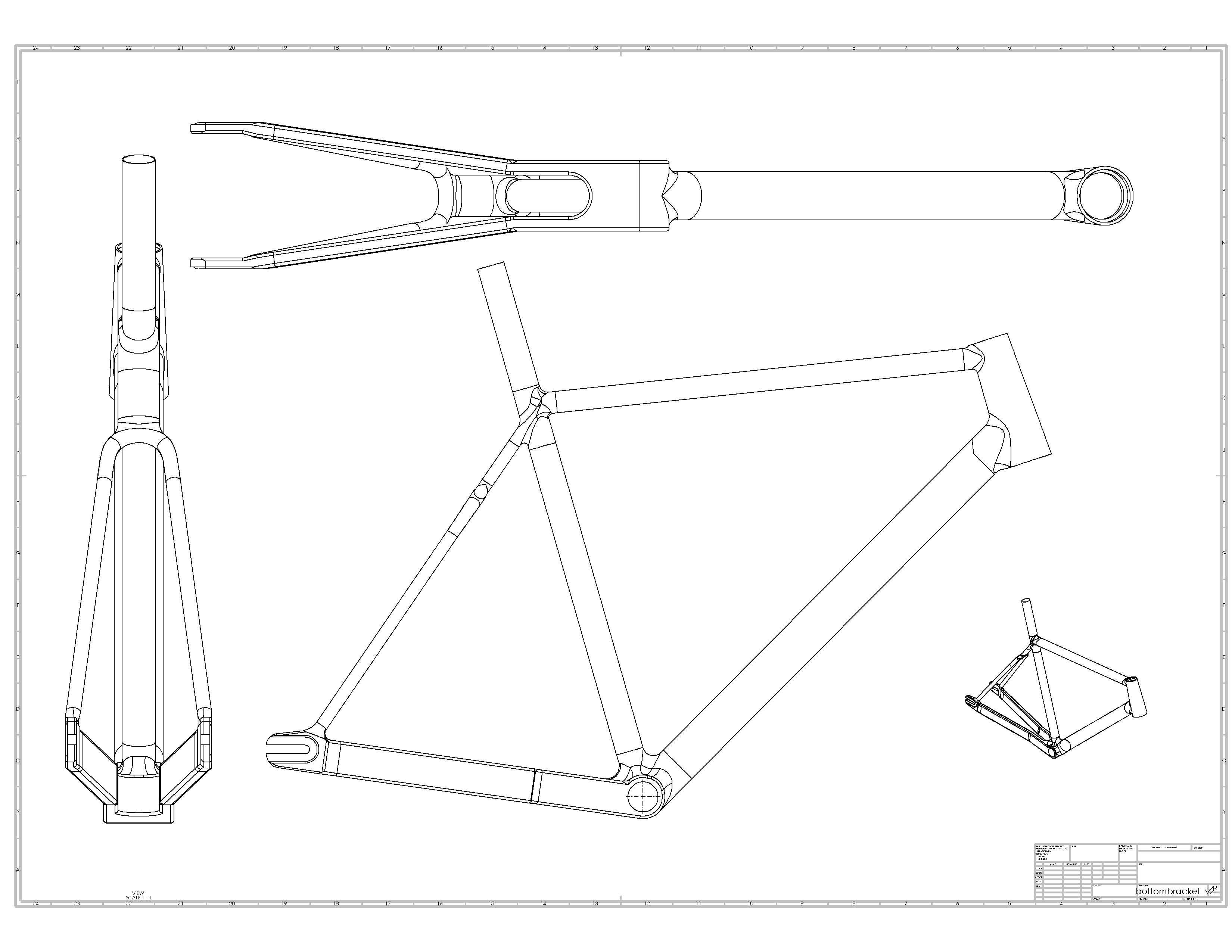
I’ve been modeling a frame that I’m planning to have 3d-printed in Titanium and I would love some feedback on the work I’ve done. I’m not formally trained in Solidworks/CAD and have just tried to learn from Youtube and online resources. I’m sure I have a lot of bad habits, so any feedback is appreciated.
As drawn, the BB lug is $3000 print! I would look into the solidworks shell tool, that is probably the best way to create a hollow structure.
For titanium, I suggest around 1.5mm wall thickness. Every printer and every part is different, but I feel 1.5mm is conservative enough without testing.
What chainline are you using for the drivetrain and tire clearance?
Thanks! Yeah the BB chunk is something that I was hoping they could work out using some gyroid infill or something like that – not exactly sure how I want to go about removing material there, as I don’t want to create any weak points in the BB.
The chainline is standard track: 42mm from BB center to chainring center. I didn’t want to make the chainstays longer than 400mm, so that’s another constraint. I’m designing around a ROTOR ALDHU crankset which is also quite close to the BB. Overall, there should be around 6mm between the back of the crankset and the BB/Chainstay wall.
Very nice, well done.
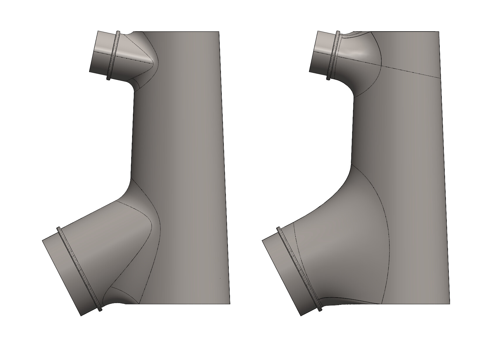
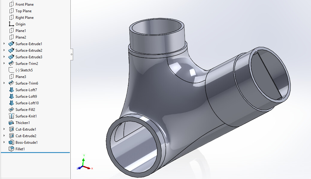
If I’m going to add something, I’d suggest that you play around a bit with surfacing techniques. Looks like you’re already pretty advanced with your modeling. The modeling can get complex very quickly when using surfaces, but when you get the hang of it a bit you can create some very nice transitions.
Much nicer than just a straight fillet in my opinion.
It’s the actual SW file so you get the history tree of what I’ve done. Bear in mind that this was just a quick 30 minute edit and I have not paid much attention to making the model robust by fully defining the sketches.
In case you can’t open the SW file, I’ve added a STEP file as well. headtube_v3_new.STEP (1.9 MB)
This is exactly the kind of help I was looking for haha, thank you for this! I’ll see if I can follow along and do the same with the other fillets that I’ve used. Thanks!
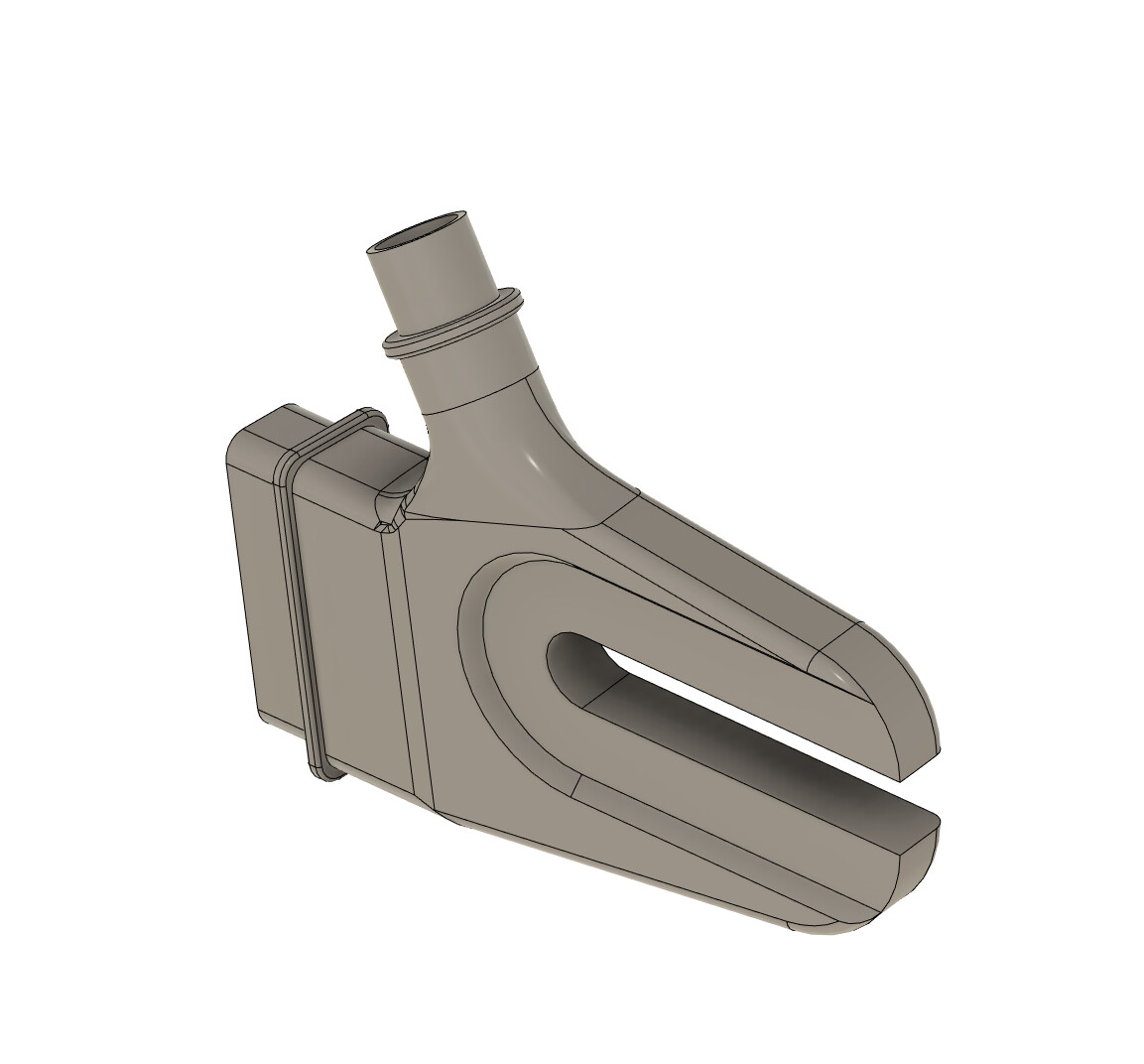
@JMY I’m just starting to dip my toes into surface modelling. I’m not entirely sure how I should be adding wall thickness. After modelling the BB or HT lug I use the thickness command adding a uniform thickness. Then I look to add/remove material around circular features using extruded boss or cuts and add any internal stiffeners using an extruded boss and fillets.
Is this the best way to go about this? Or is there a variable thickness command I’m missing? Or maybe when printing these parts they should all have a uniform wall thickness? I’ve never printed a lug before but hoping to on my next build!
This is exactly the method I started with, and it should work well.
Uniform thickness should work for most applications and you can, as I see you’ve already done, add strategically placed ribs and reinforcements for extra strength.
As far as I know there’s no variable thickness option for the shell command.
I’ve also found that the shell command can be temperamental - especially if the solid you’re trying to shell contains tight radii. In these cases the shell command will often fail or produce an error.
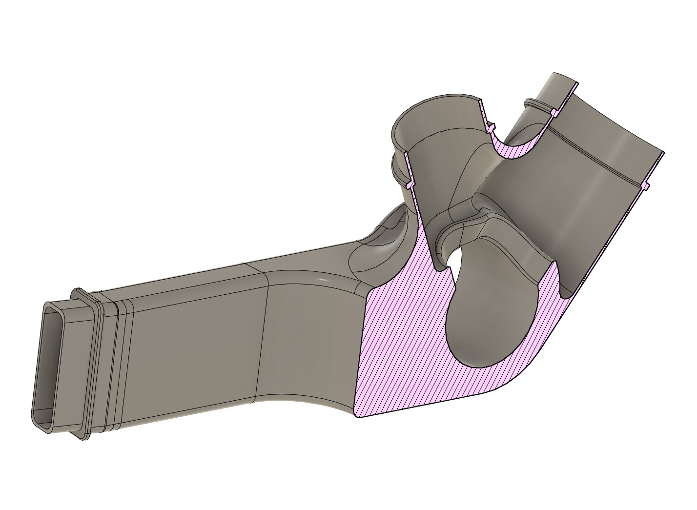
I’ve played around with a couple of methods to achieve variable wall thicknesses.
Option A:
Duplicate the solid you want to shell.
Shell one body to a thick wall and the other to a thin wall.
Split the solids along an appropriate plane.
Delete the extraneous bodies - i.e the thin wall and thick wall bodies you don’t want to use
Combine the remaining bodies into a single solid.
Experiment with ways to “smooth out” the transition from thin wall to thick wall. Chamfers, fillets, or surface trims and patching are some options.
Option B: [Warning: This is way more time-consuming and requires a lot of planning to build the model appropriately from the ground up.]
This method can’t be detailed with a simple step-by-step list, but it essentially involves modeling the outer and inner surfaces separately using carefully planned wireframe reference features built up with various on-plane sketches and 3D sketches utilising style splines to create smooth wall thickness transitions.
I then use the boundary surface command to build up the shape, playing around with the various tangency options to achieve a model with smooth surfaces.
The outer shape of the body can be turned into a solid. The inner (hollowing) shape can either be a solid that’s subtracted from the outer shape, or you can leave it as a surface and use the ‘cut with surface’ command.
Neither of these methods are easy to make sufficiently robust to handle parametric geometry changes in a predictable manner.
I spent weeks modeling the the latest lugs I designed for a new prototype frame. Mainly using method B. I’m very close to a fully parametric model, but some features still fall over when making certain geo changes.
I’ll do my best with Option A and test my prints in PLA before committing to a stainless print. I’m excited to dive more into surface modelling and seeing the resulting prints!