After a number of run of the mill diamond frames I needed to build something different. Years ago I saw a line drawing of a Dursley Pedersen in the Archibald Sharp book -Bicycles and Tricycles. (Great book BTW, well worth a read if for no other reason than to show how many ideas are not really new, they were just waiting for more modern tools materials to come along and make them practical.)
Pedersen was the designer and patented it in the early 1890s. Dursley is the city in England where most were built, generally between the late 1890s and WW1. The theory behind the design is that all loads are resolved in tension and compression, there is no bending moment. These are still produced in small numbers by a couple of builders in Europe, but are pretty much non existent here in the US. My own frame jigs would be useless for this task so yay-big fun ahead.
Having some history with rag-and-tube airplanes (Piper Cub/Champ/Taylorcraft) the truss type construction attracted me. I found pics on the net, enlarged them and used a protractor and ruler to obtain the angles, then used the 700c wheel diameter to scale the lengths. Real scientific, I know, but it actually worked out quite well. Seems the originals were made from 14mm tube, 9/16 from Aircraft Spruce was (2011) $7/ft but 5/8, commonly used for the above mentioned aircraft, was only $2/ft and I’m a tall guy so that is what I used for the first frame. 32 ft of .035 wall plus a pair of Columbus chainstays in all.
Due to the general weirdness of this design they were originally available in 6 or so different sizes and not being able to try any I had to make mine with the seat tube height adjustable. More fun. There will be a 1/16”wire cable from the rear dropout to the seat tube top when assembled which is not clear in any of the pics. This made “adjustable” even more fun.
So, pics below showing some of the process. These are a mix of 2 builds, the second for my wife, and is made from 1/2” material as it is smaller and I was still too cheap to buy the 14mm stuff. The astute observer may note that after the first frame I had a friend with a huge CNC add a channel along the bottom of the backplate for those 2 bars to slide in, less clamping and way easier. Apologies for the pic quality, many were on an old camera and I was always in a hurry.
I had a big piece of 5/8 aluminum tooling plate handy so off I went. Note that a lot of the bits involved with this jig are from other projects so many of the holes and other features are superfluous. And yes, I own a lot of clamps…
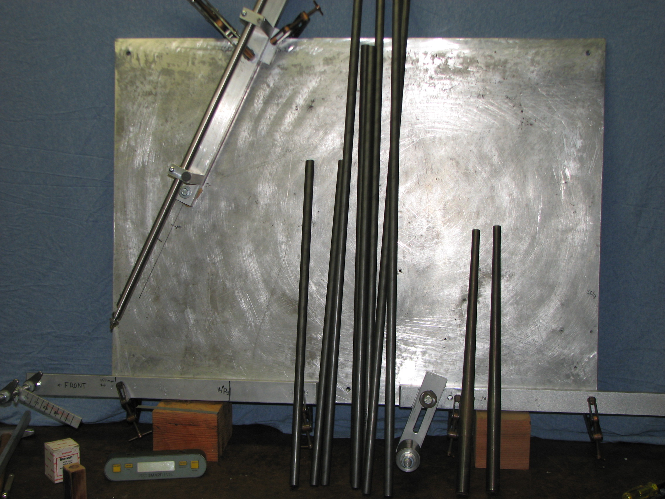
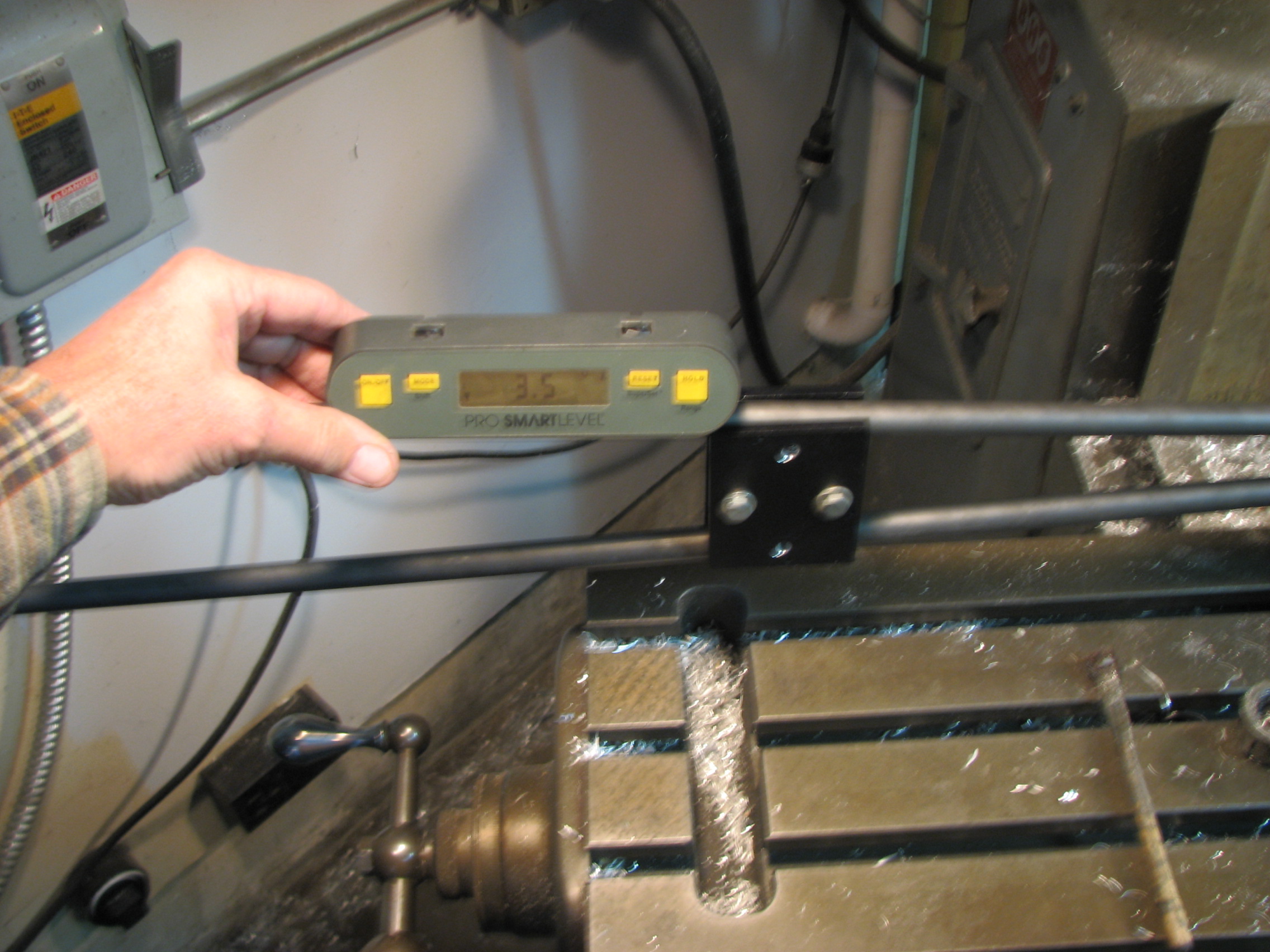
Establishing the HT angle WB, BB location and rake in one shot. Rod with point on end slides down to meet the scale below it.
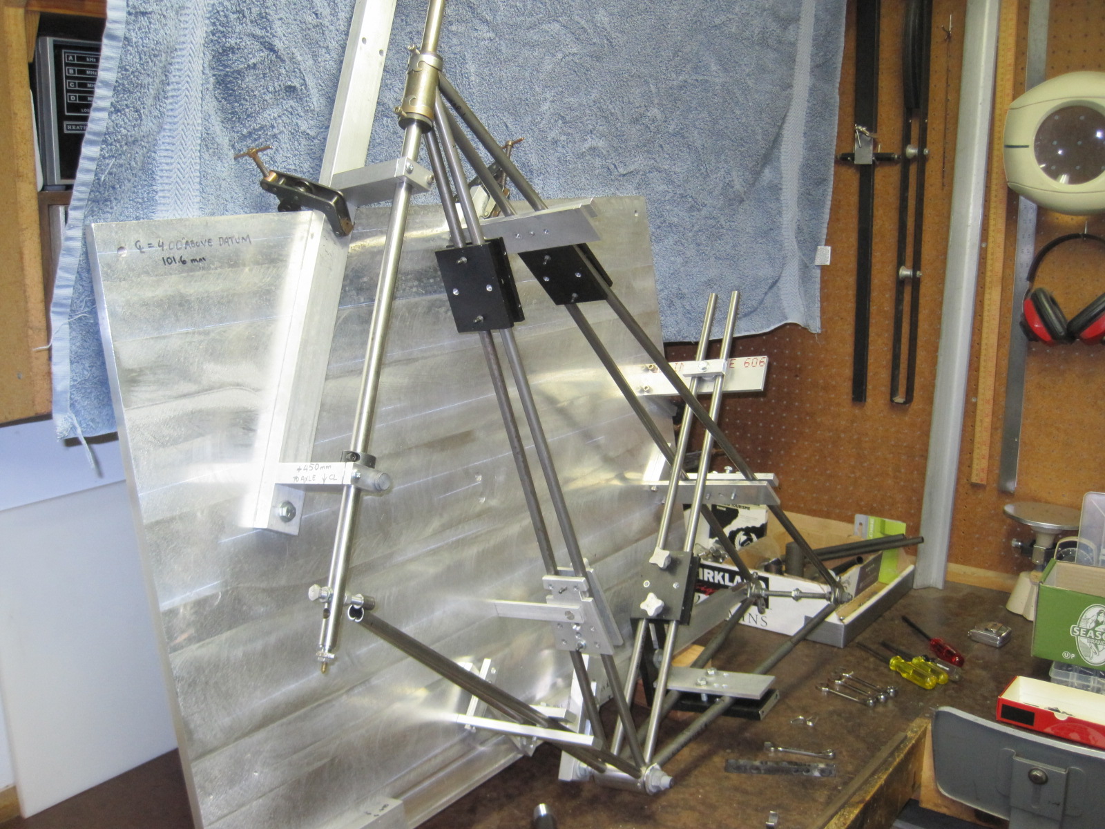
Starting to look a bit like a bike. (well, to some people)
I got brave as time went on and mitered them in pairs. Mr Bridgeport was quite a help.
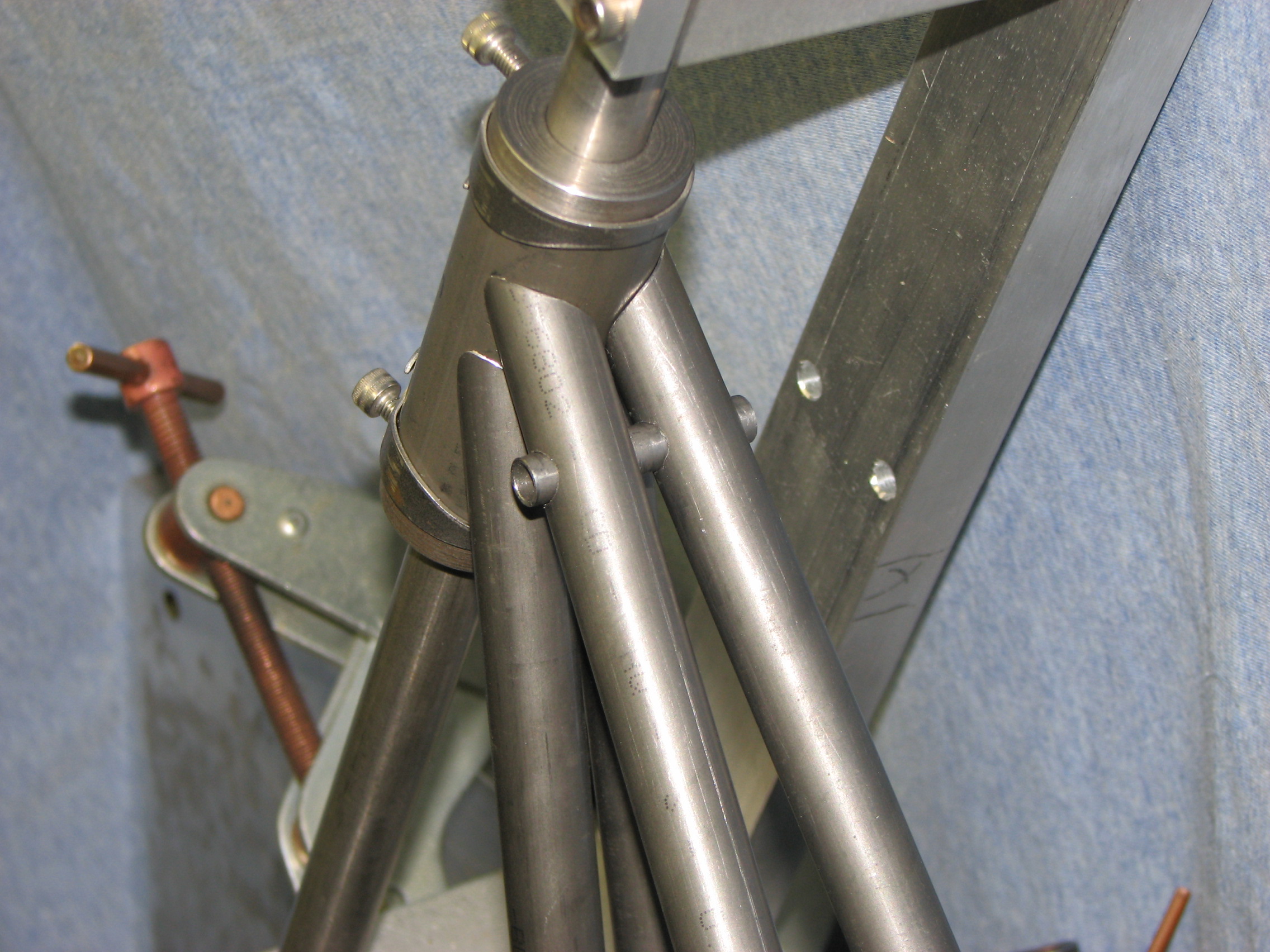
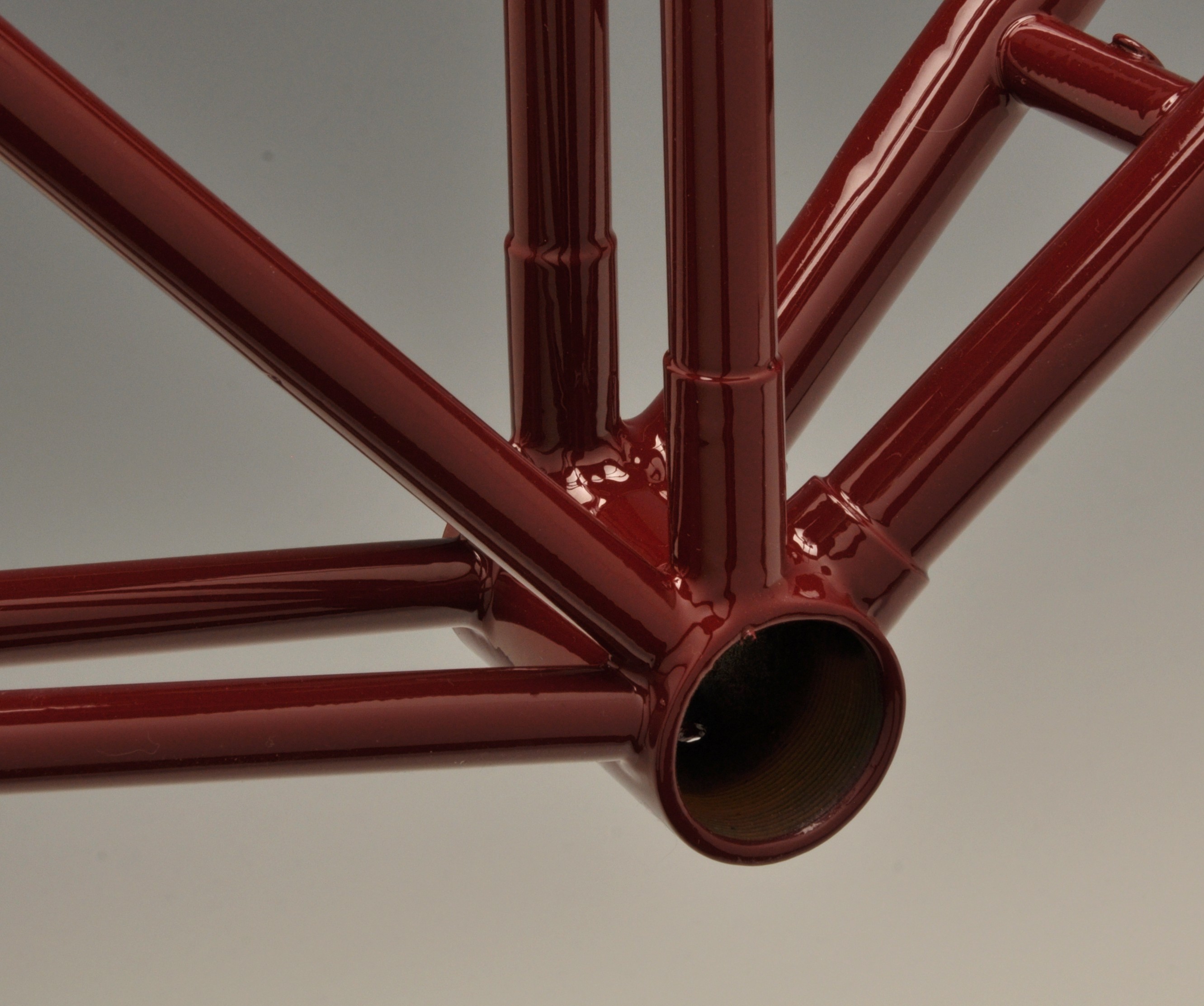
Head tube junction before cleanup, the small (8mm) cross tube is for the seat suspension strap. I have no idea how this was done on the originals, but good luck doing it with paper templates. The really steep/hard miters were done first.
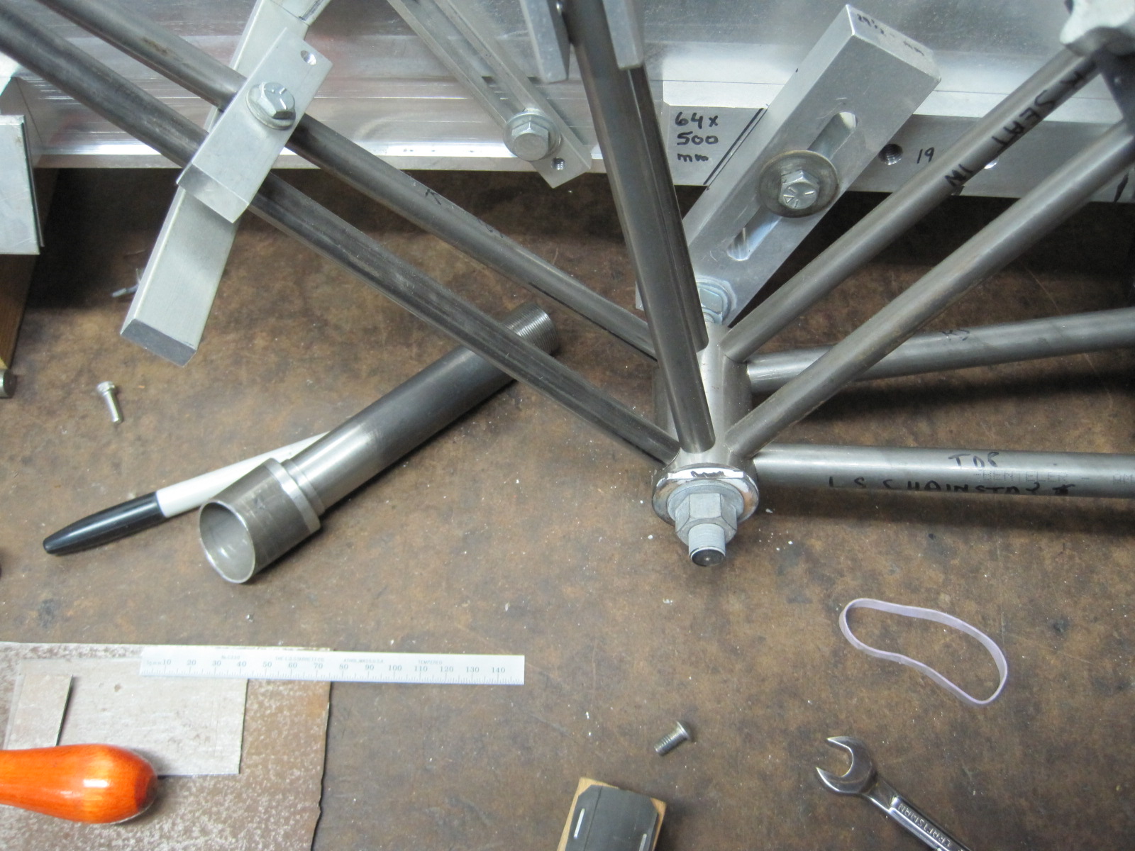
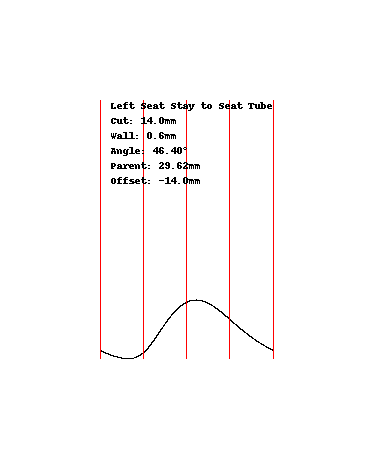
These were easier, scribe a line and miter with a hole saw. The tubes were held in a C5 collet block which I left on for fitting. Err on the long side and whittle your way back if needed. Angles here were only about 3 degrees. The part on the bench is the steerer/fork crown.
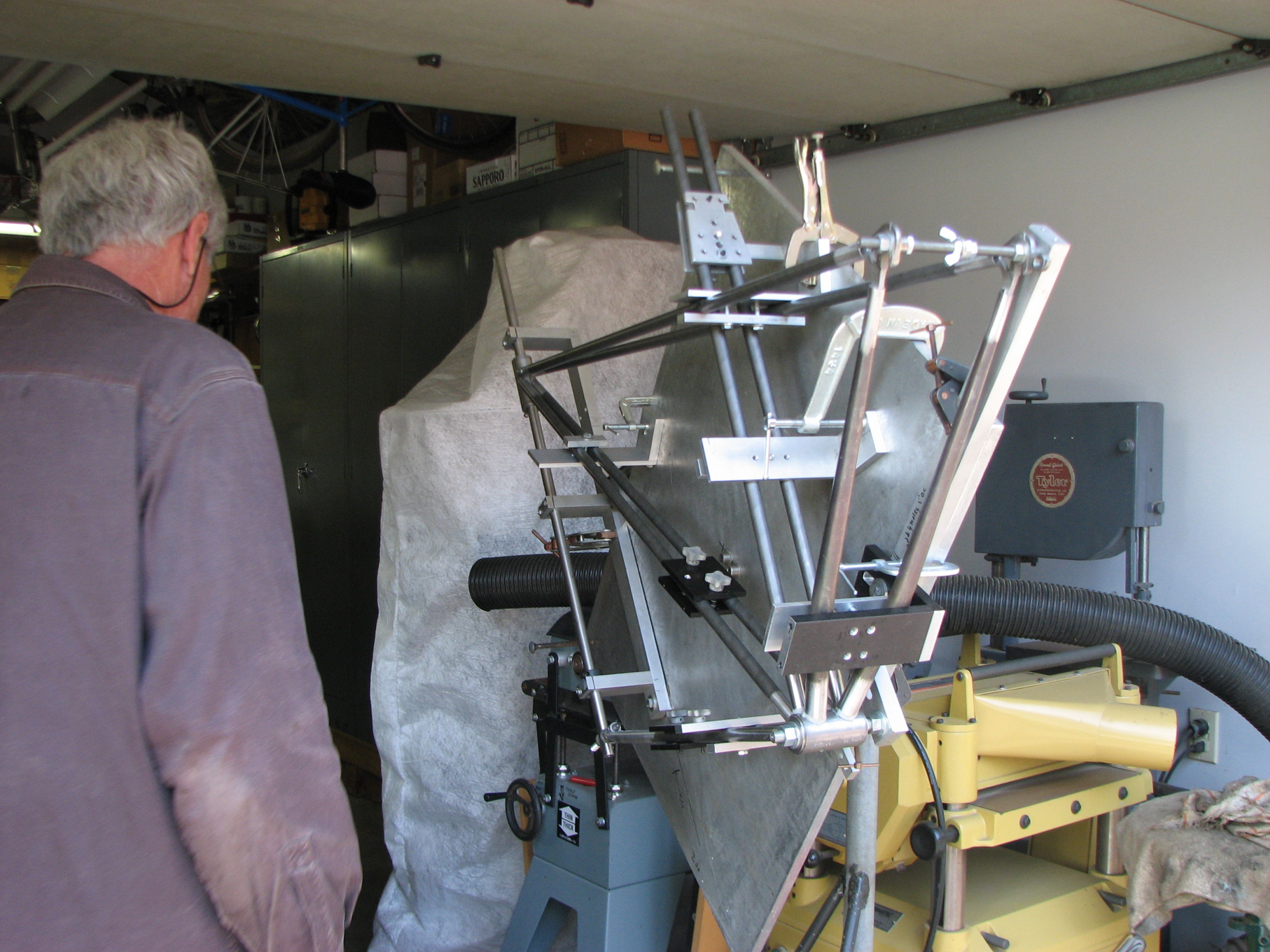
A younger me wondering which joint to braze first. Individual tubes could be removed for fluxing as I went along. The jig can rotate as needed and (not shown here) I mounted it on a cheapo hydraulic lift table so I could raise and lower it as well.
The fork was built similarly and there are a couple of pics in another post. As odd as it is the bike rides very nicely with the hammock style saddle. Very upright and you can easily see (and be seen) around. More detail pics can be posted if there is interest.