Hello guys!
My name is Aleix and i am from Barcelona. I’ve been riding bmx and mtb all my life, digging trails (worked at La Poma Bikepark) and after studying mechanical engineering i have decided to gather all my effort and make my own frames in my free time.
I’ve worked at a Bamboo Bicycle manufacturer for a couple of years and i am now starting a new career at a composite manufacturing team that makes cool racing stuff so that’s my professional background. I studied machining for 4 years and manufacturing in general so touched a bit here and there on all possible ways of making stuff.
Being new here, i thought it would be great to document my first build struggles as i develop the skills, design and make the tooling, the frame and anything related with the process.
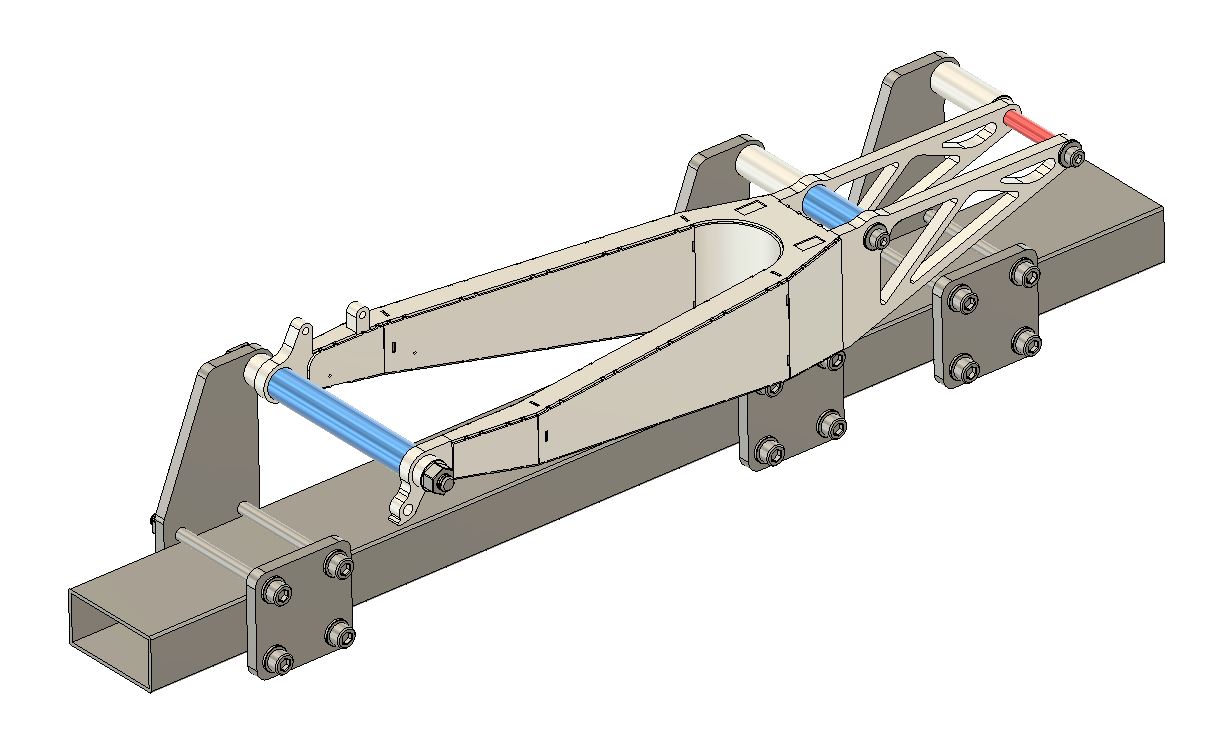
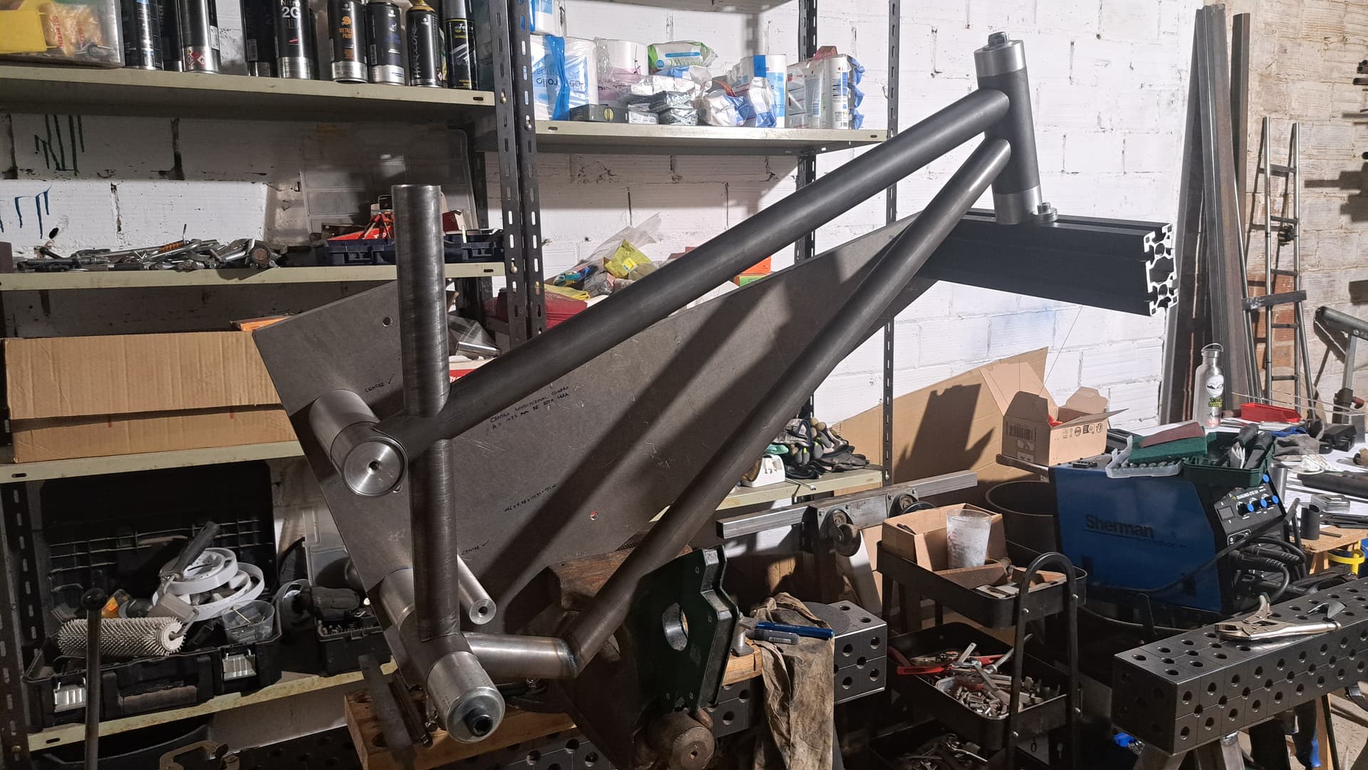
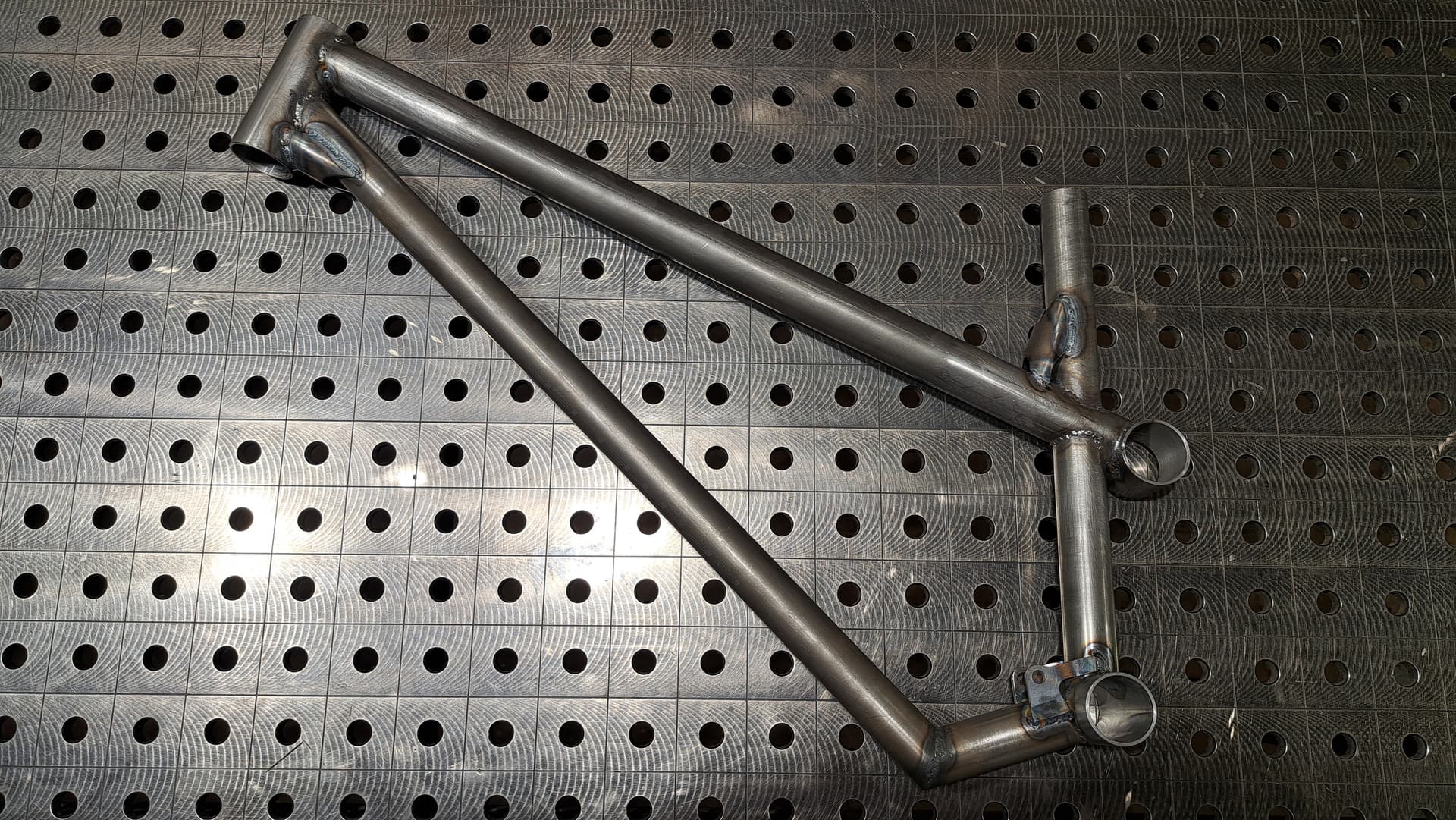
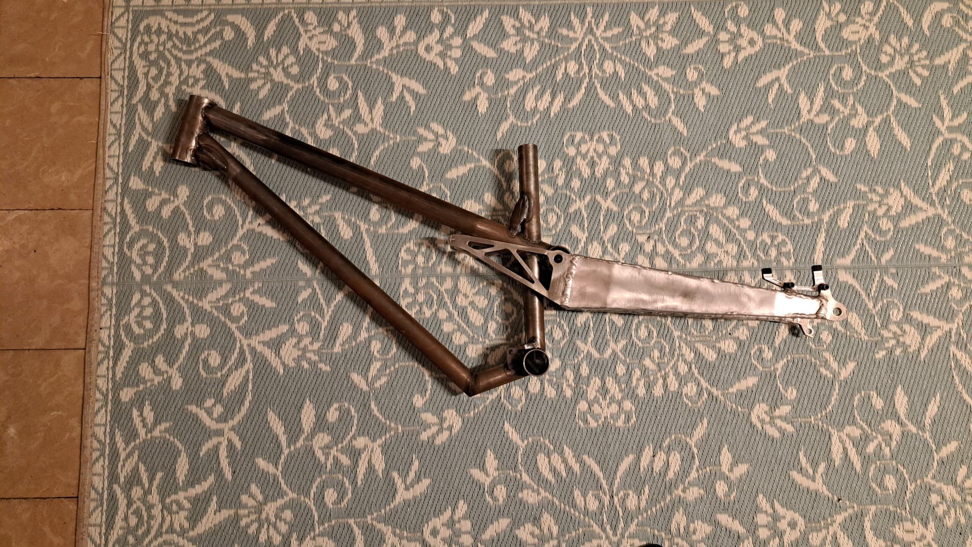
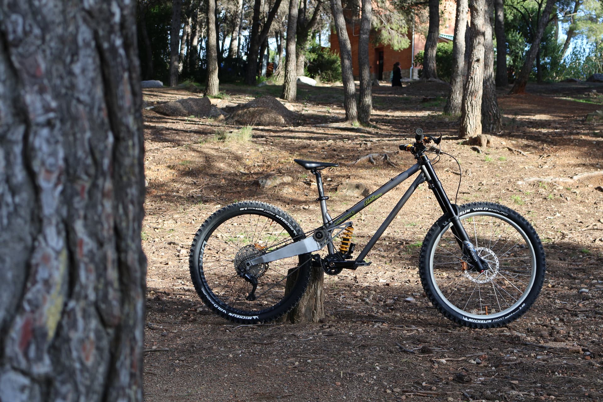
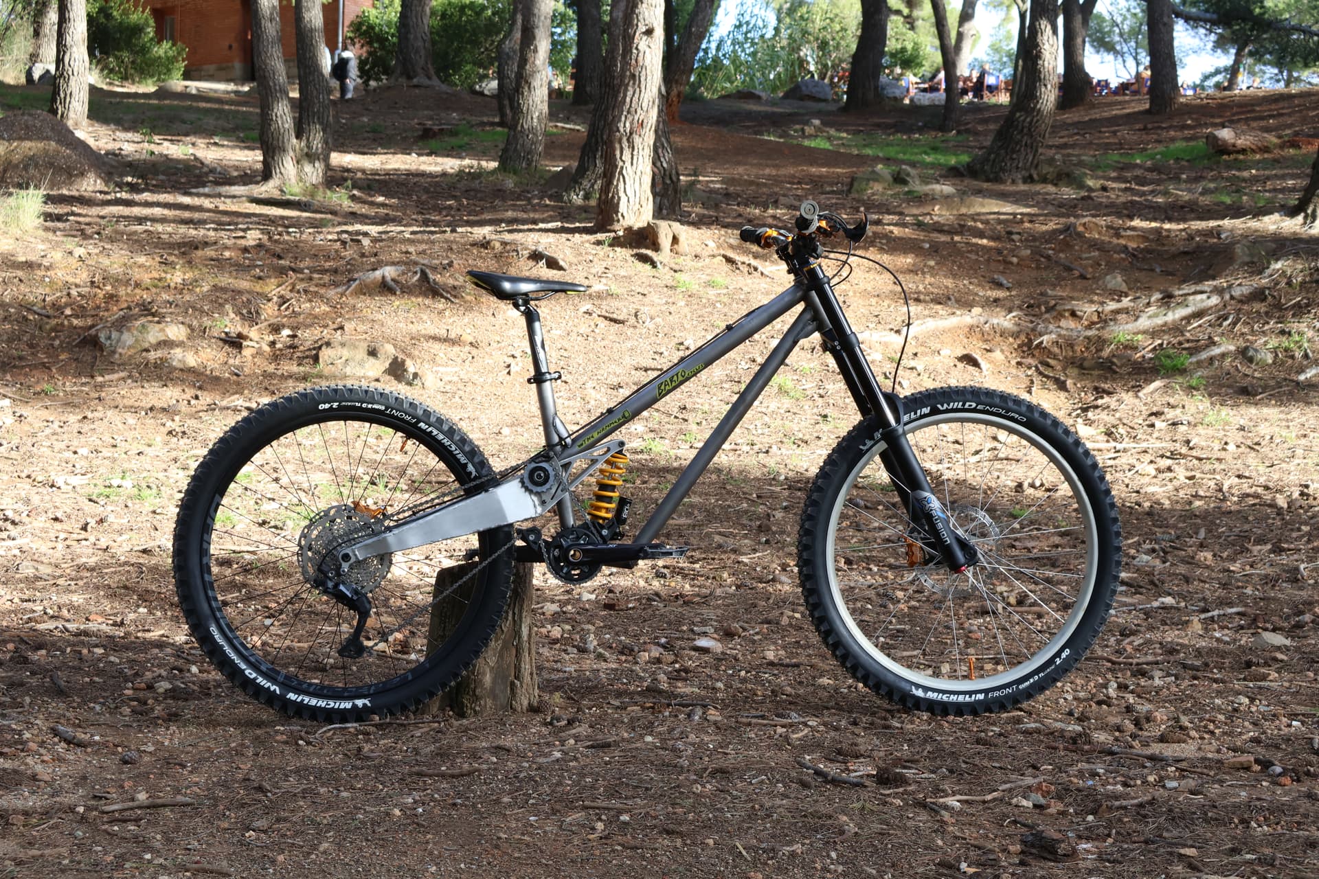
So here’s the frame!

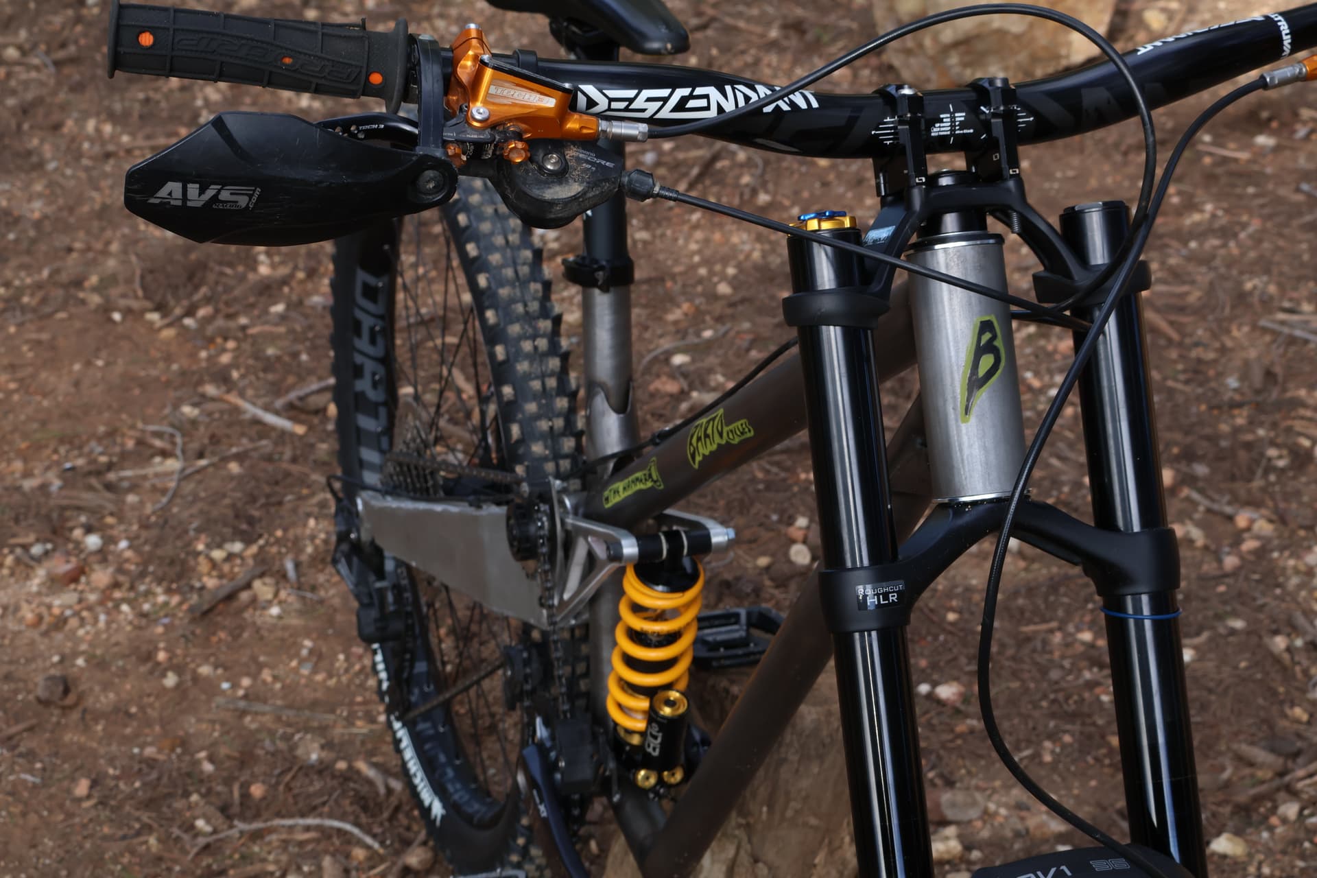
I’ve named it “The Hammer” since it just sounds metal and it is a tool that works great for everything plus it always comes handy when things go south. I live in Barcelona so the mountains around here are Mediterranean, which implies dry conditions, very rocky (sharp knives) and heights of up about 500 meters~. I would consider myself a pretty gravity focused rider, so the bike is designed around the use of double crown forks, and giving it a try at the more recent geometries proposed for people the likes of Aston Mtb and Cahal = Long Boy. My bmx background is whispering behing my ear to not do it but i am not listening and going full for it.
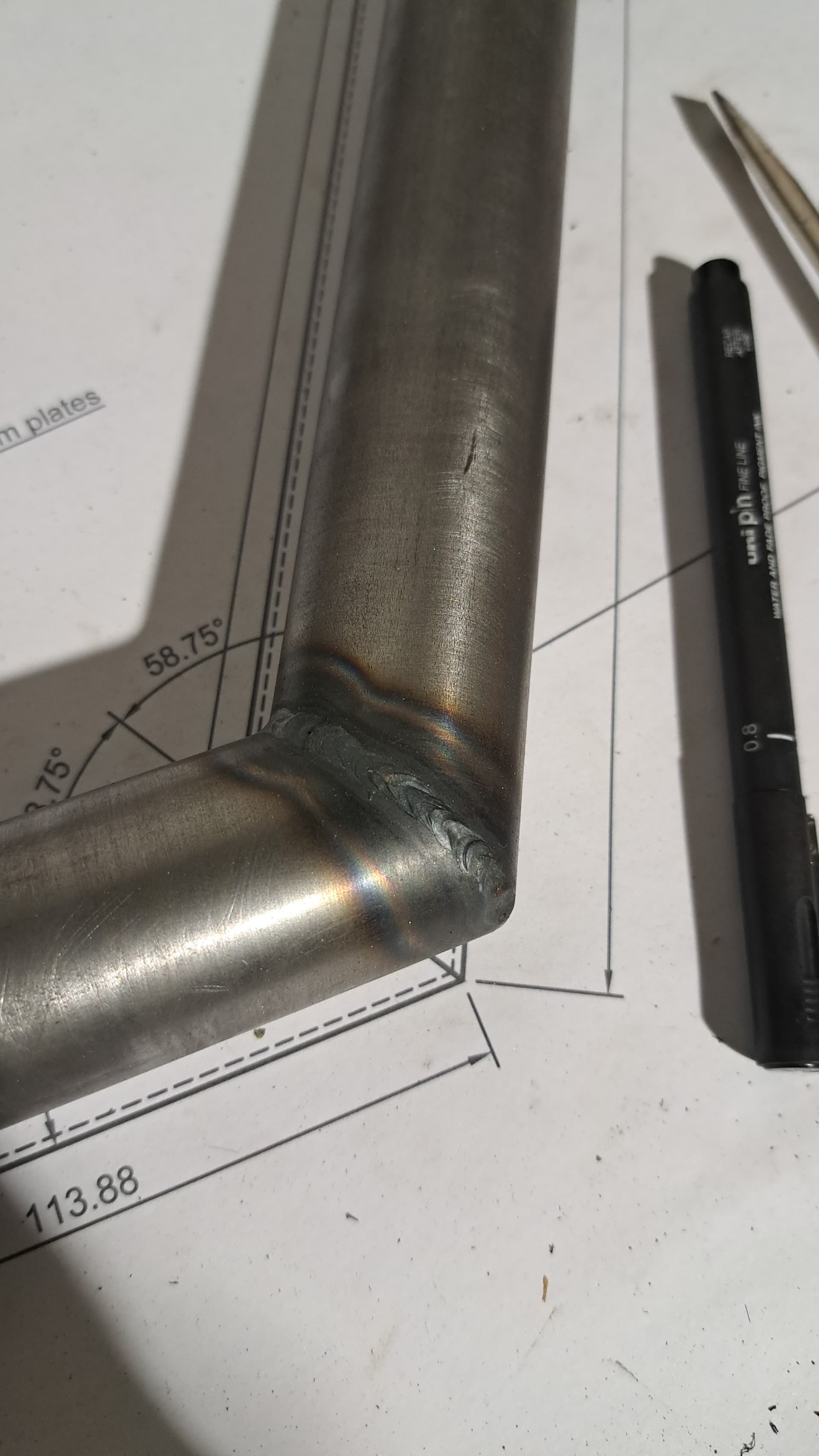
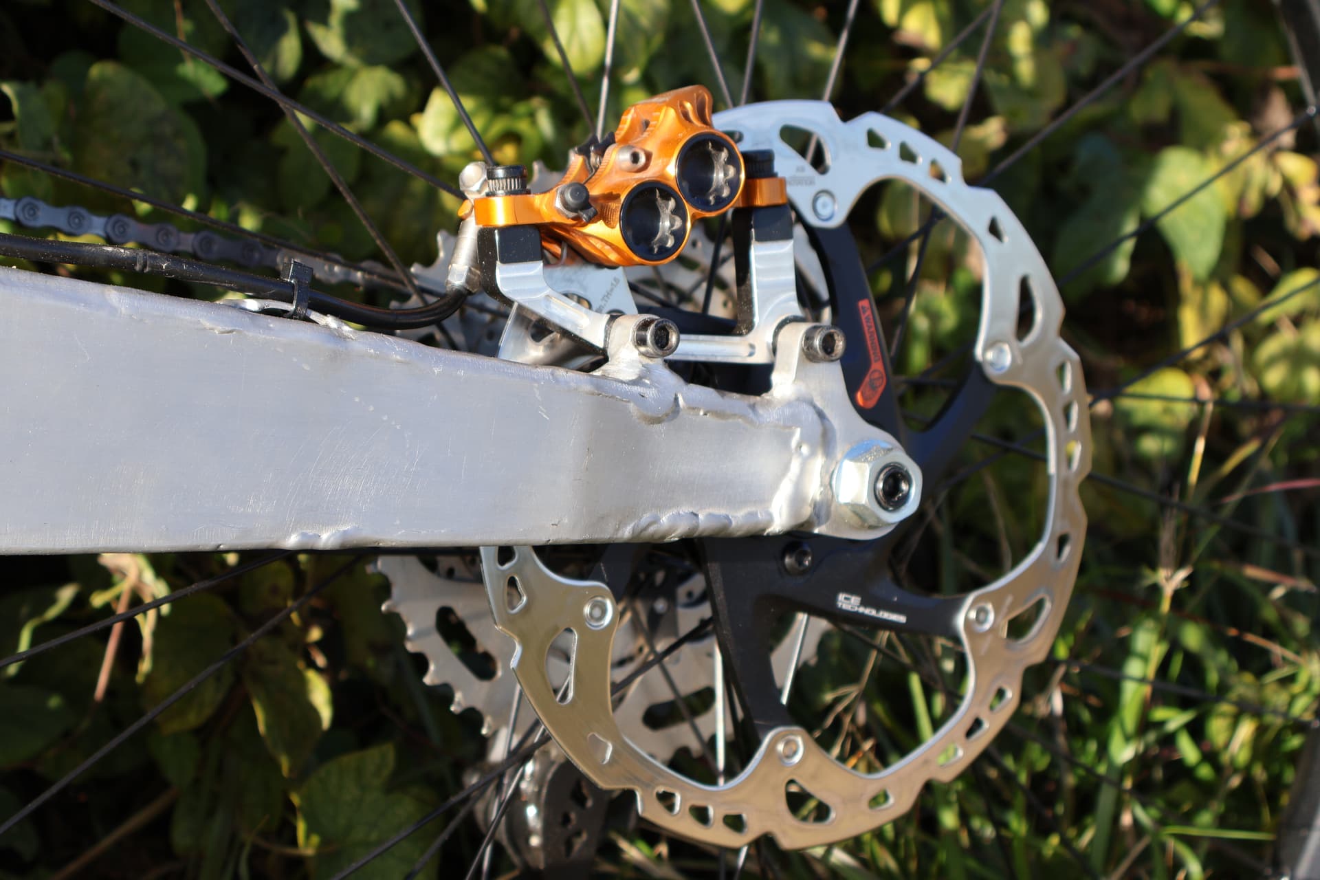
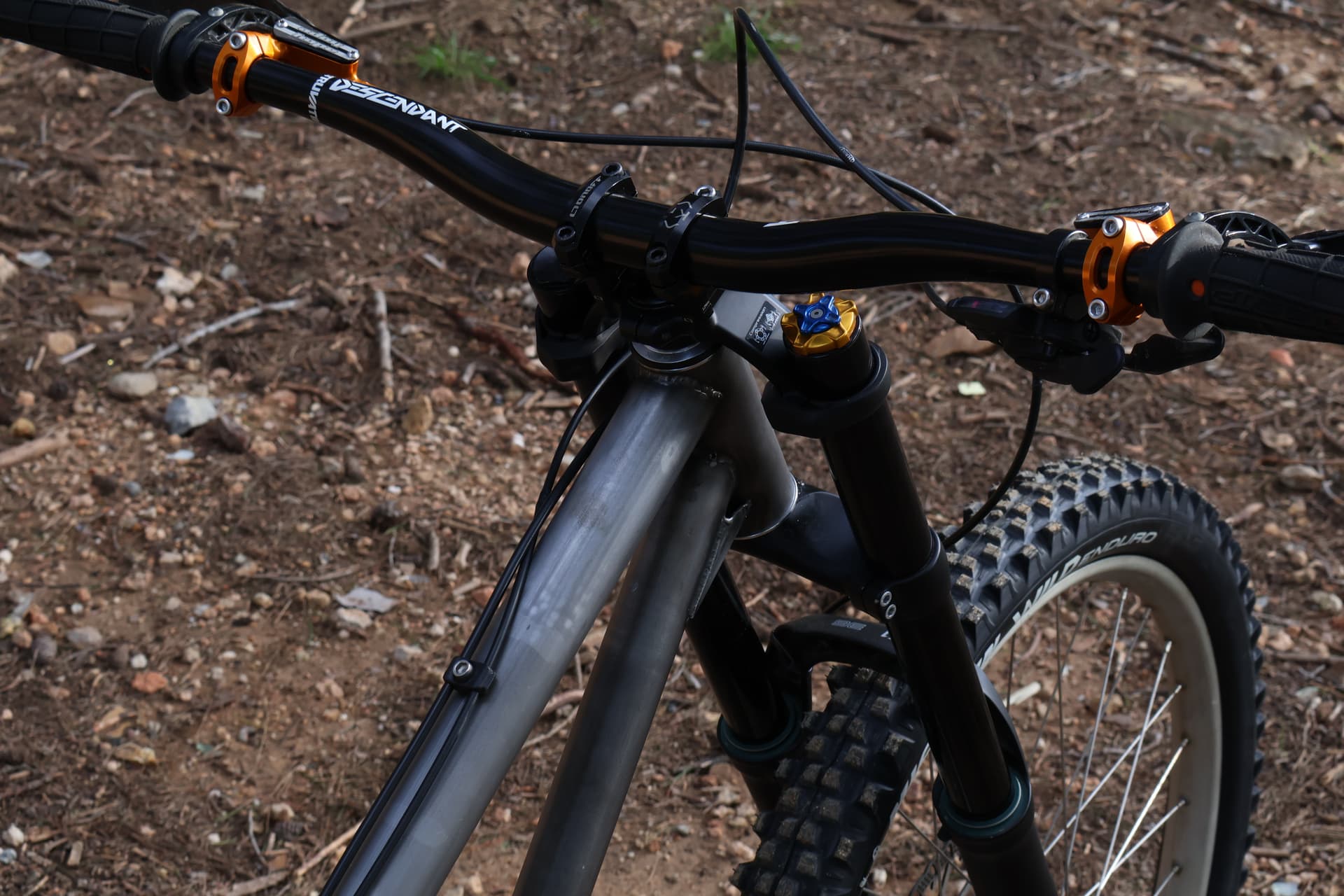
The frame is made to run 27,5” front and rear. With 160mm vertical at the back, plus a 180mm front forks at 63º Head Tube angle which equals to 160mm of vertical travel aswell. Chain stays are 480mm and Reach 490mm. I used linkage X3 for the kinematics plus Fusion 360 for the 3D modelling. The Bottom Bracket Height sits at 310mm at 30% SAG which might prove a bit too low for the frame since it is basically a Balfa BB7 / Appalache Real affair result…
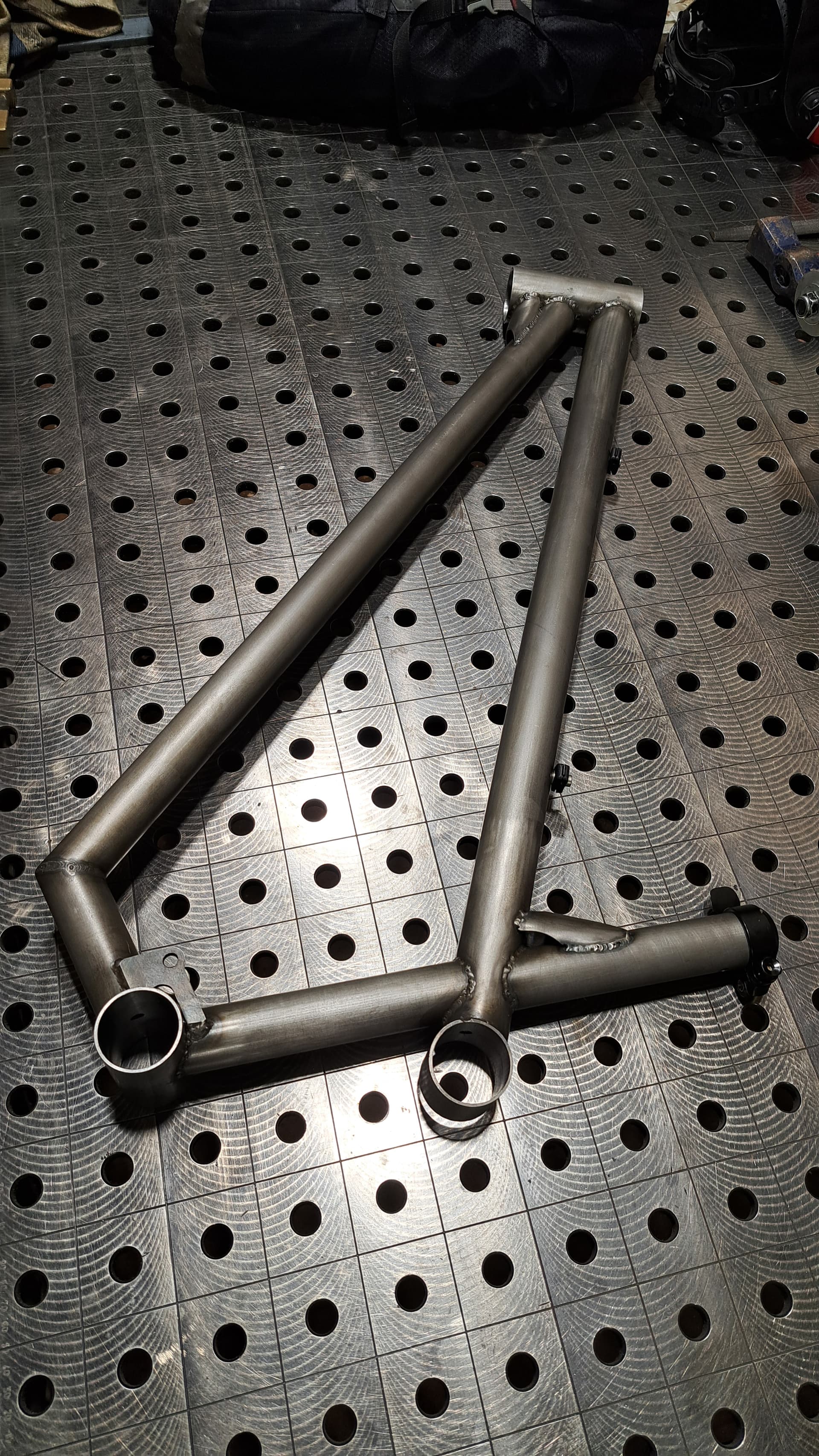
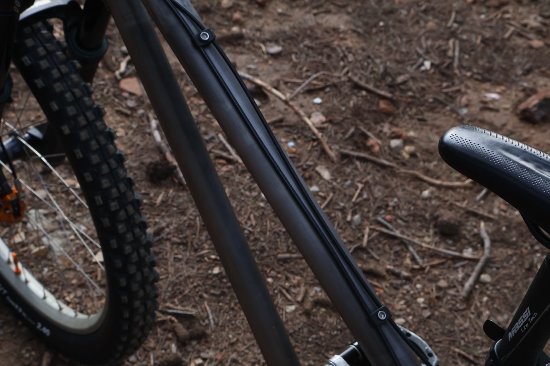
I have found a European supplier for the Tubing, which is 25CrMo4 and i am using:
- TT = OD 40mm wt = 1.5mm
- DT = OD 35mm wt = 1.5mm
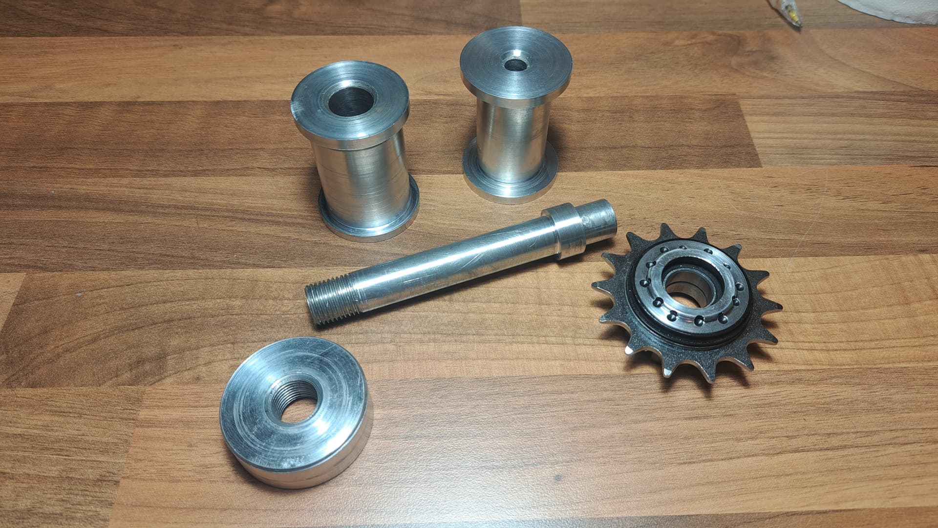
- ST = OD 35mm wt = 2mm which will be reamed to 31.7mm post welding
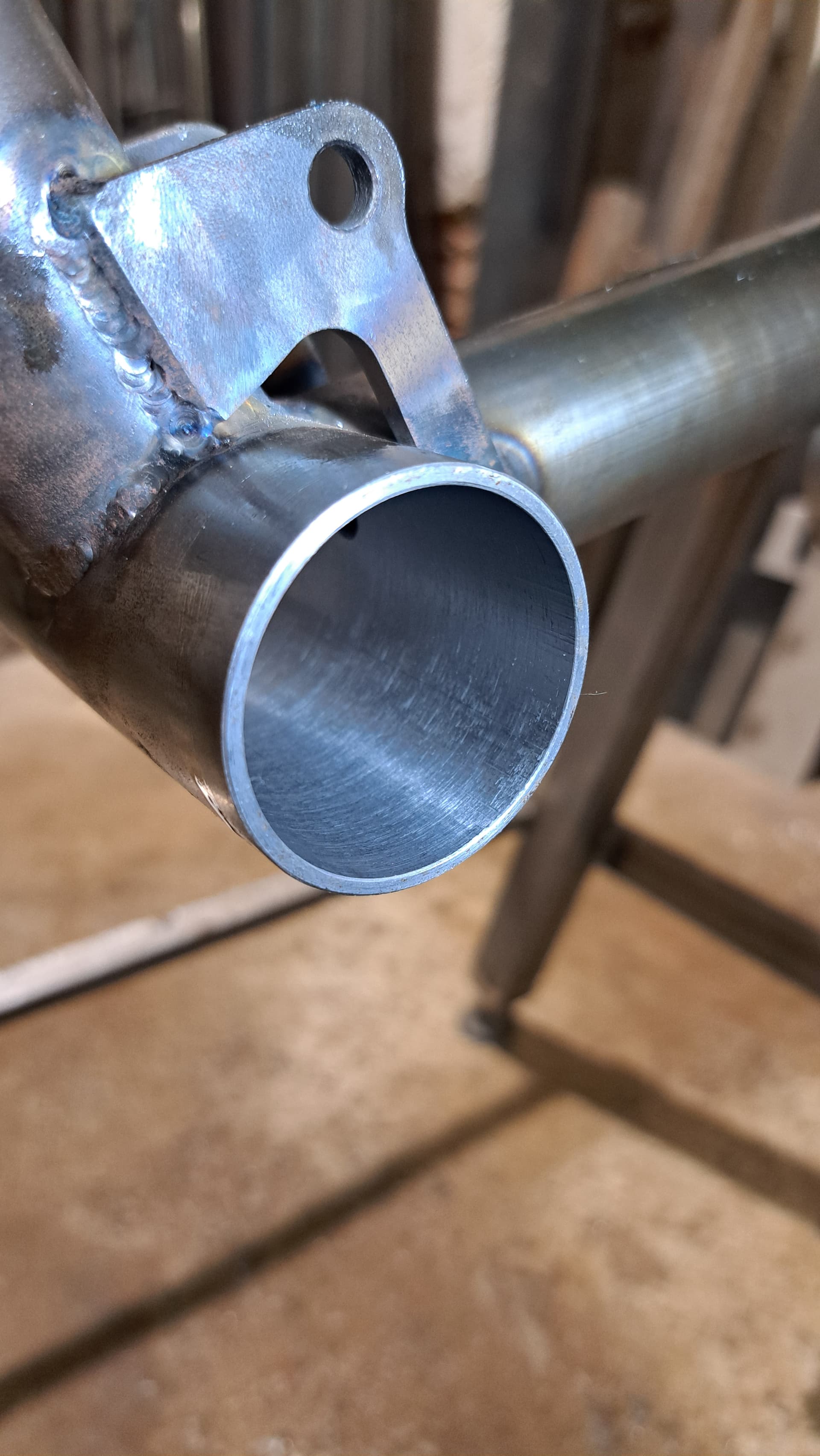
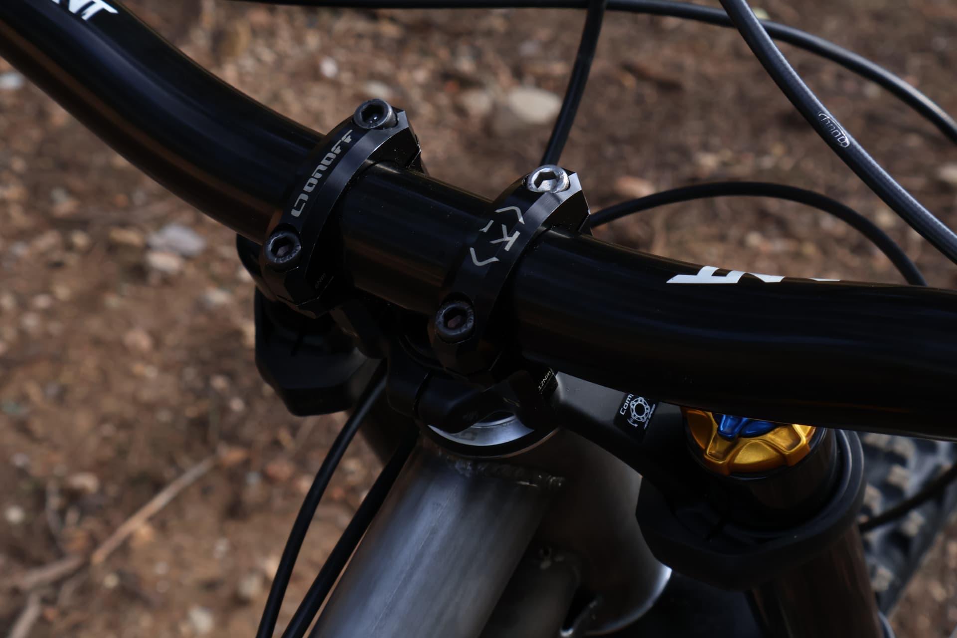
- Head Tube and Main Pivot housing = OD 48mm wt= 2.5mm. Both will be reamed to ZS44 to run regular ZS44 1 1/8” headset angular contact bearings. The idea is to get two Headsets and have all the bearings done.
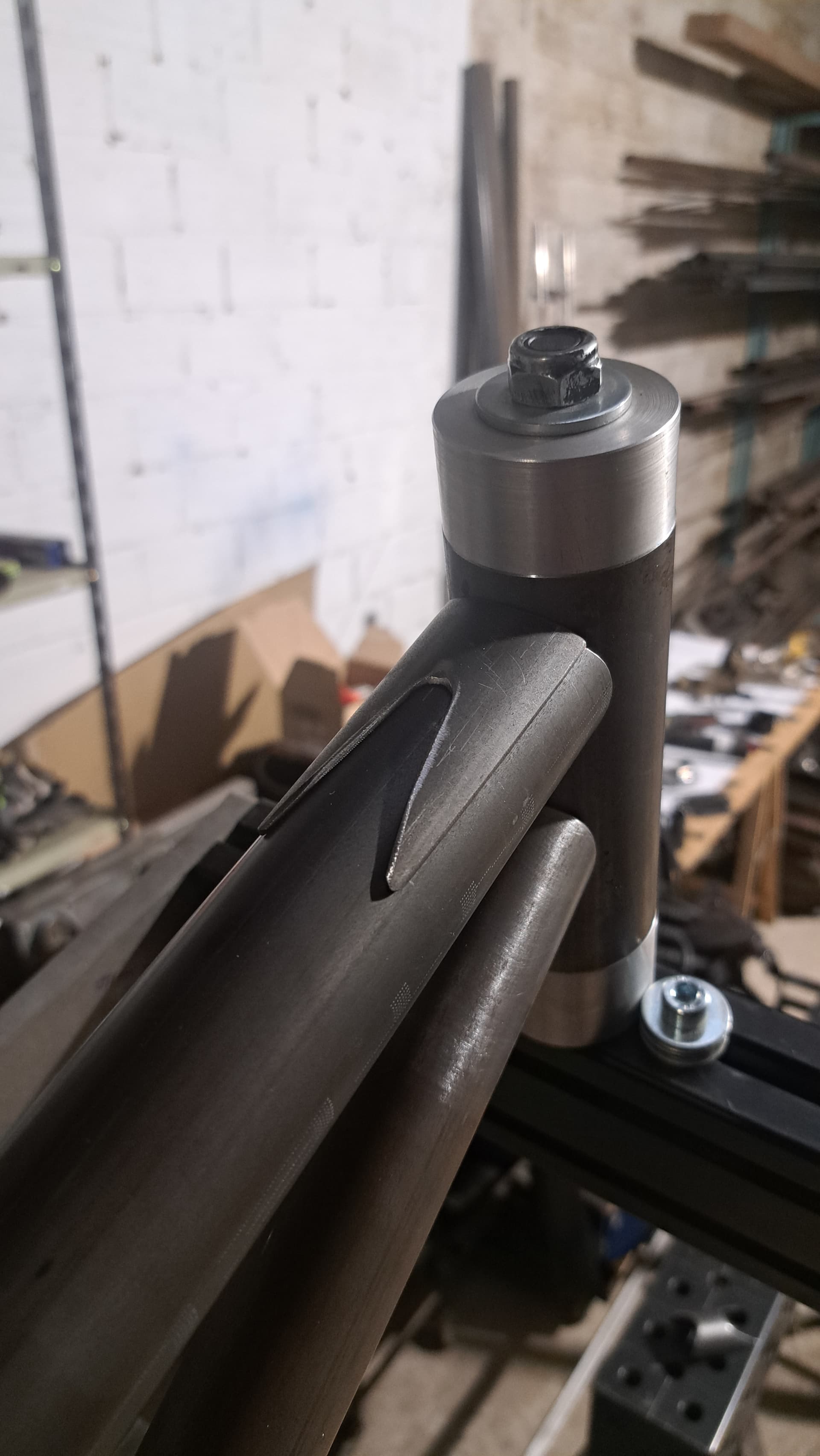
- The gusset tube i am still leaving room for improvisation, might do some curved cool stuff, don’t know atm.
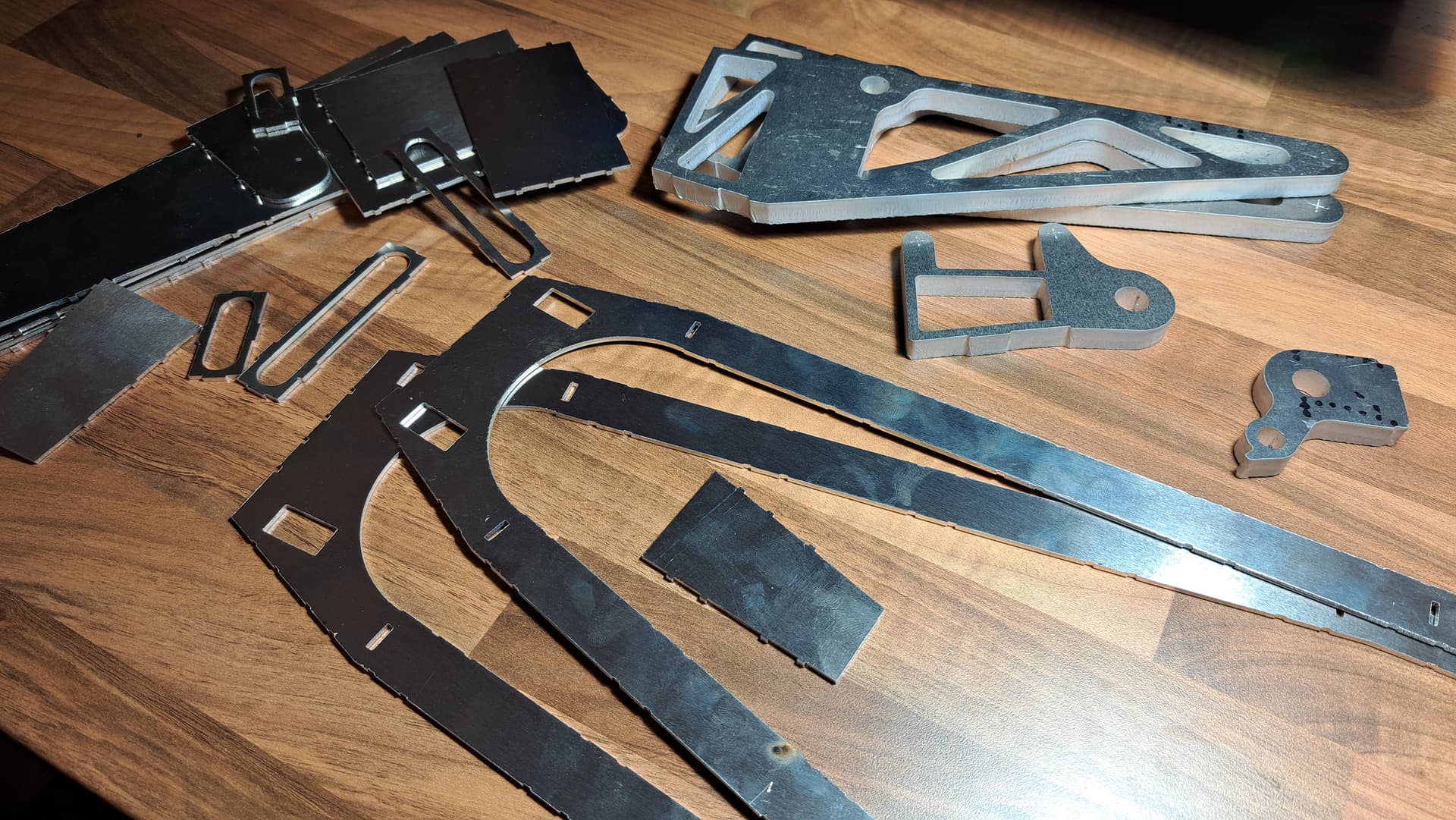
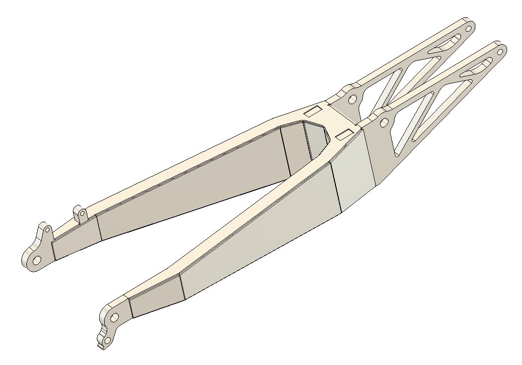
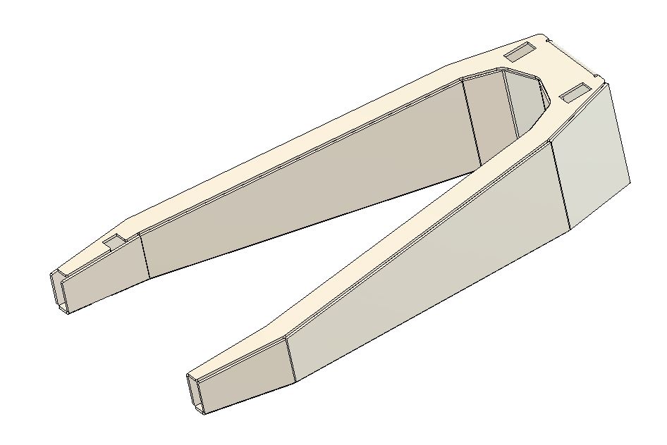
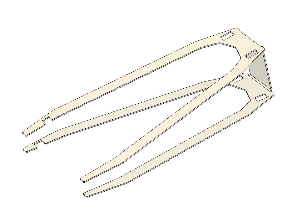
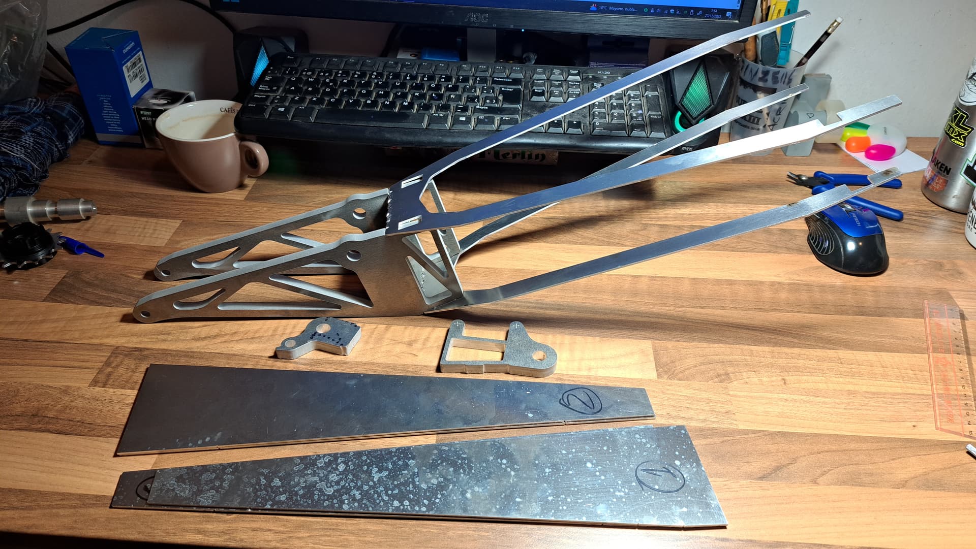
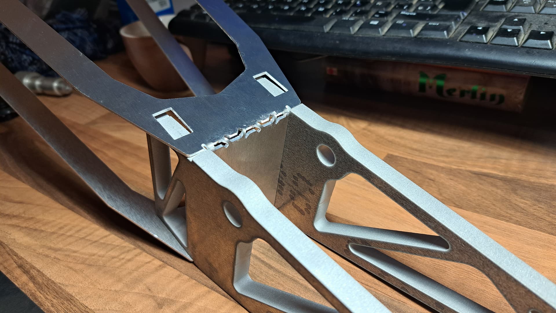
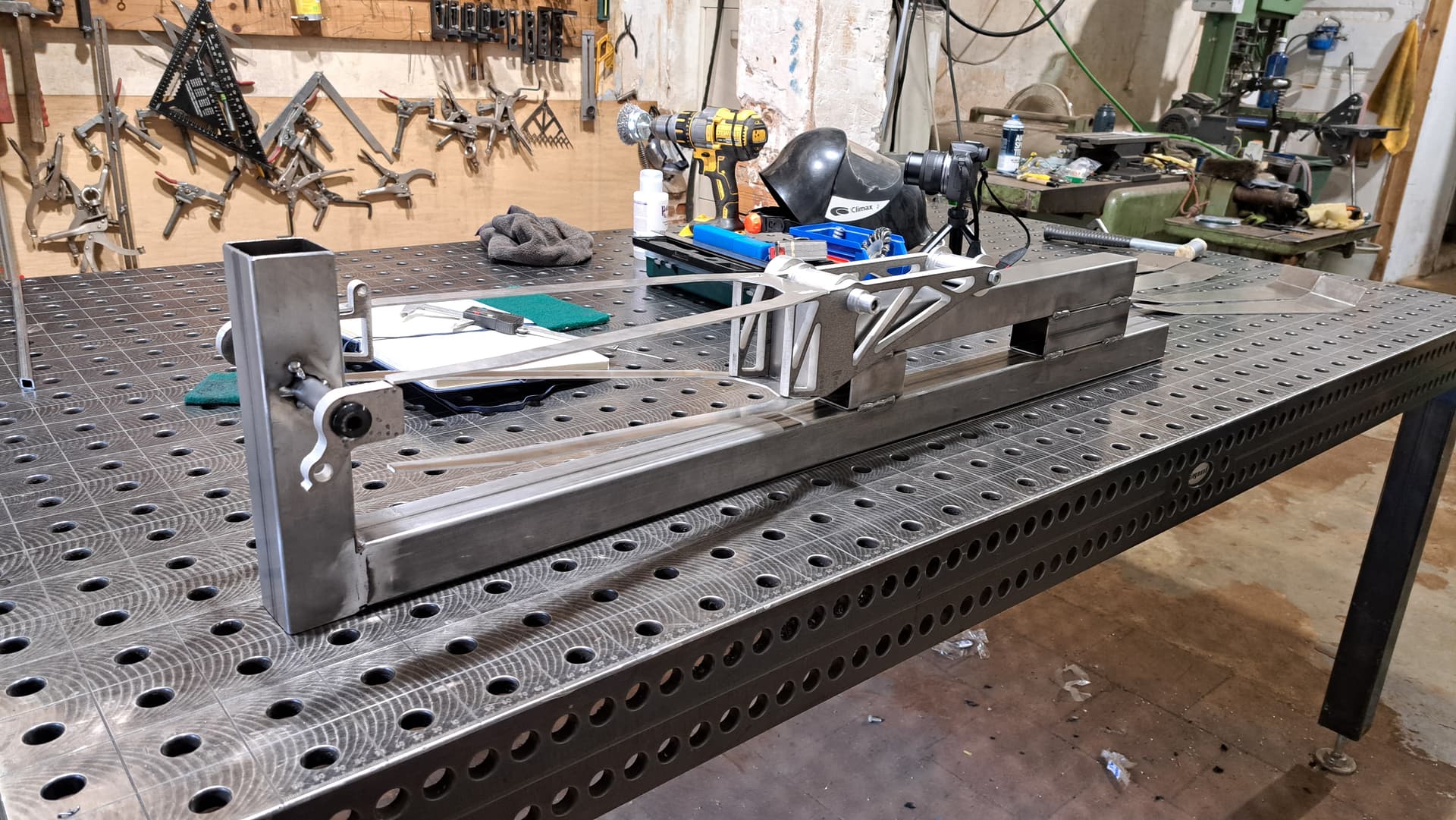
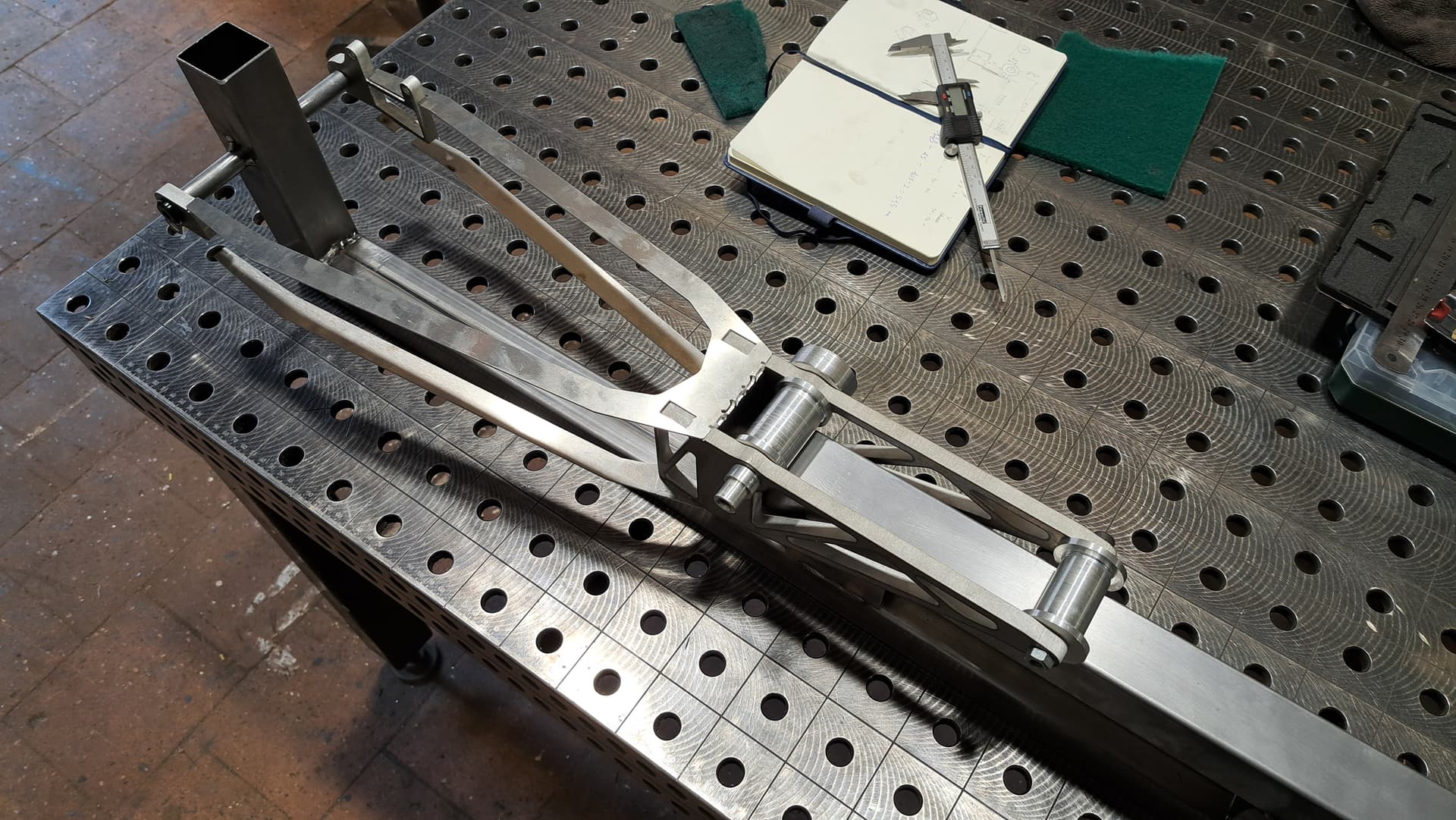
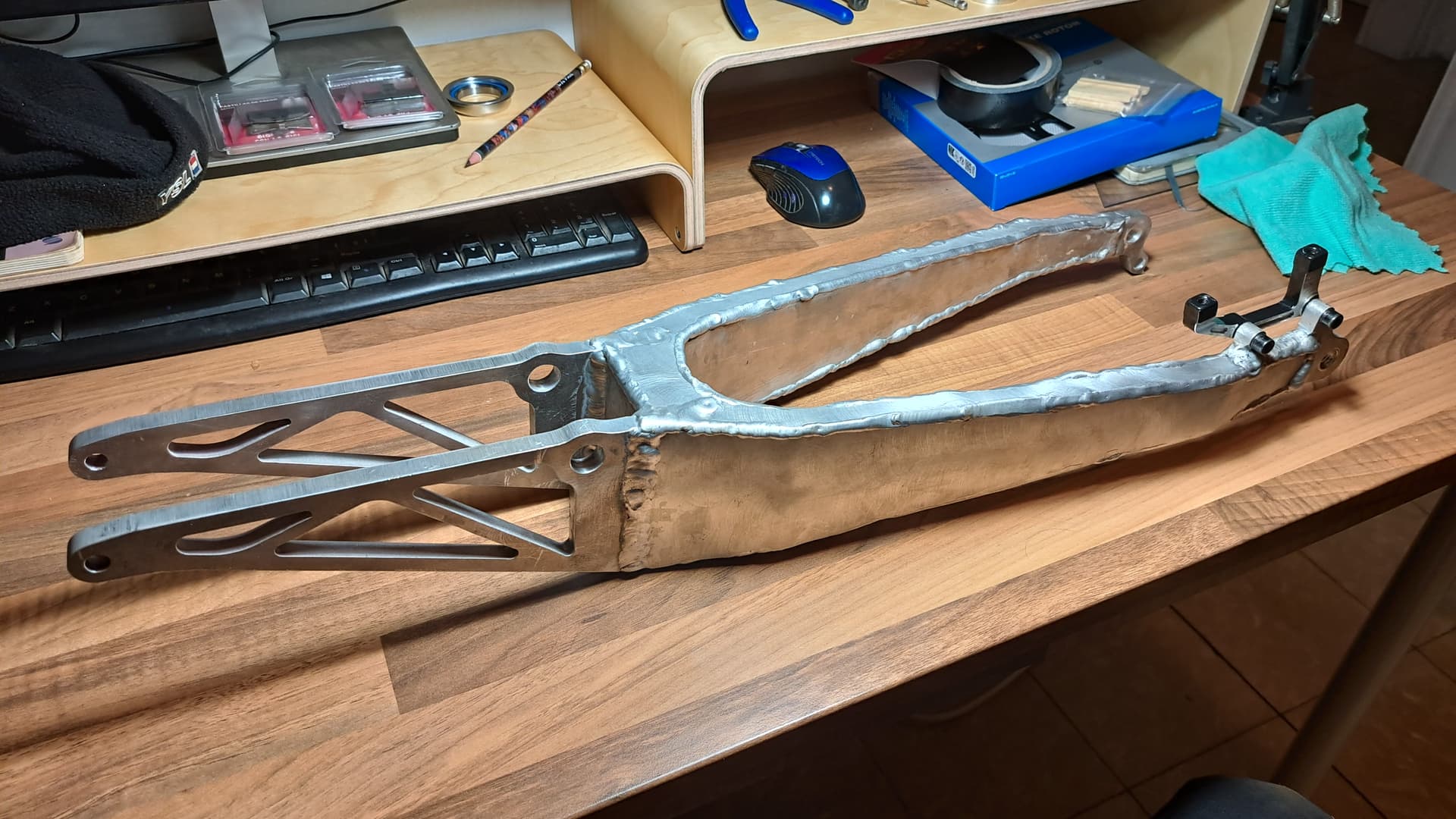
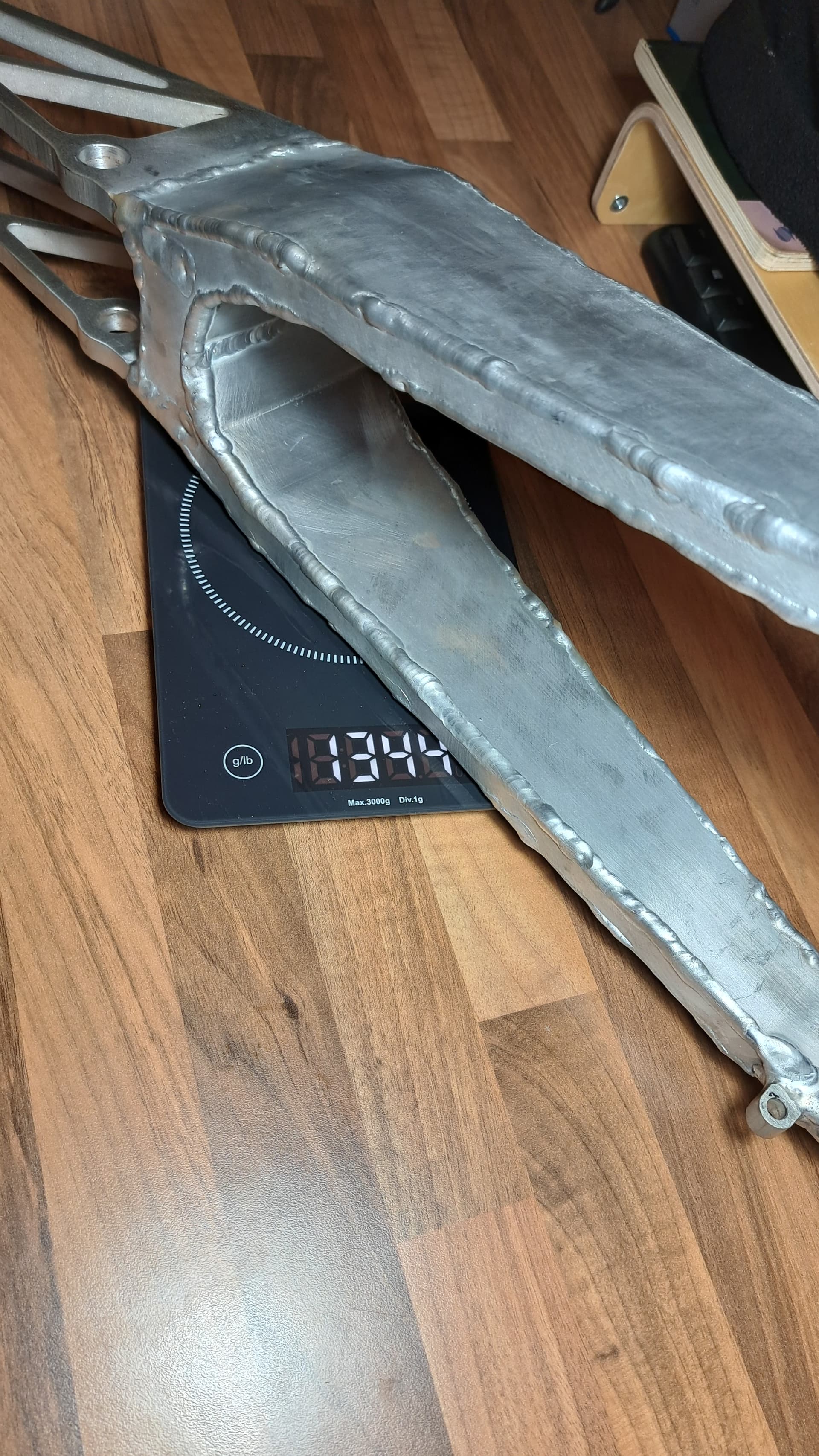
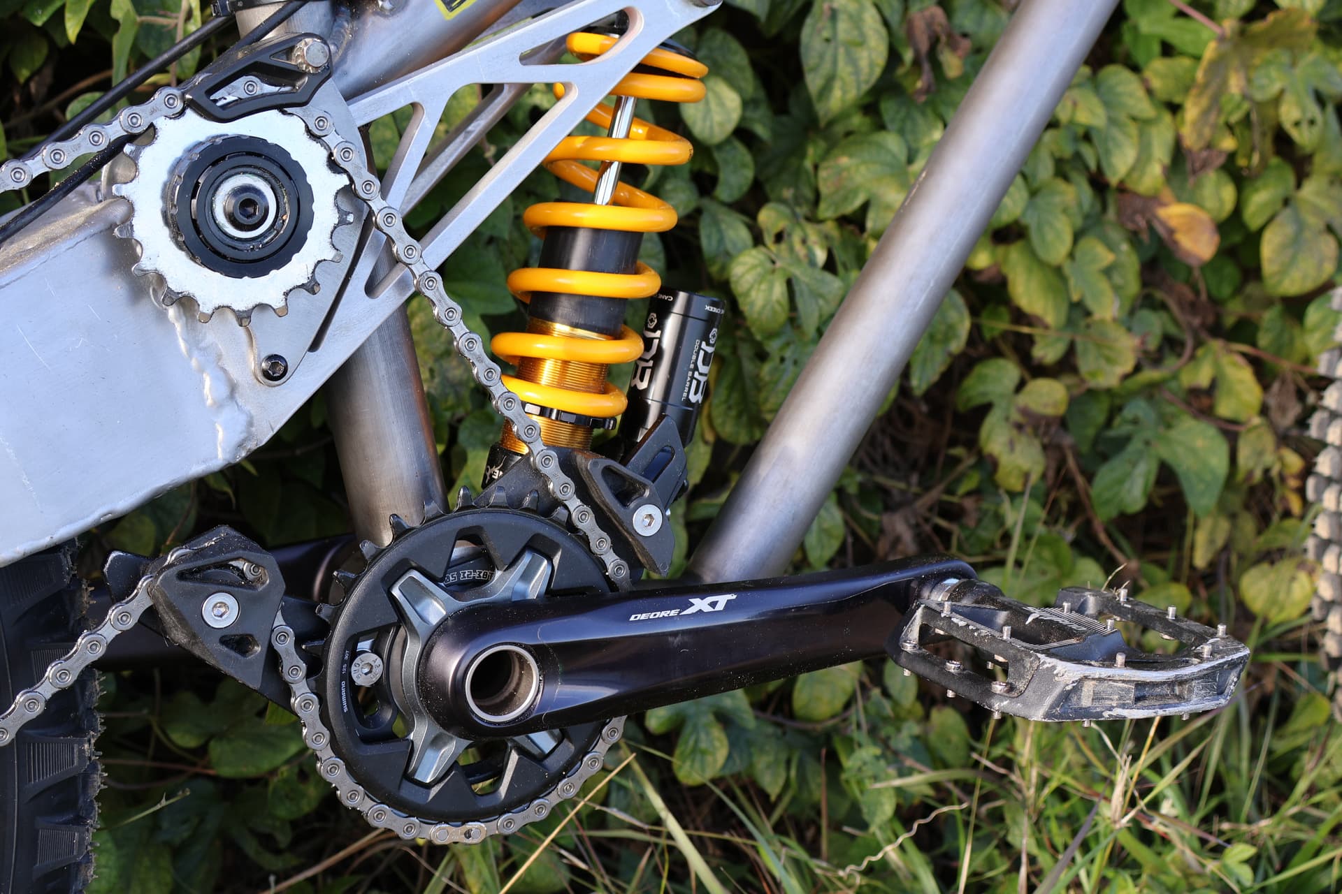
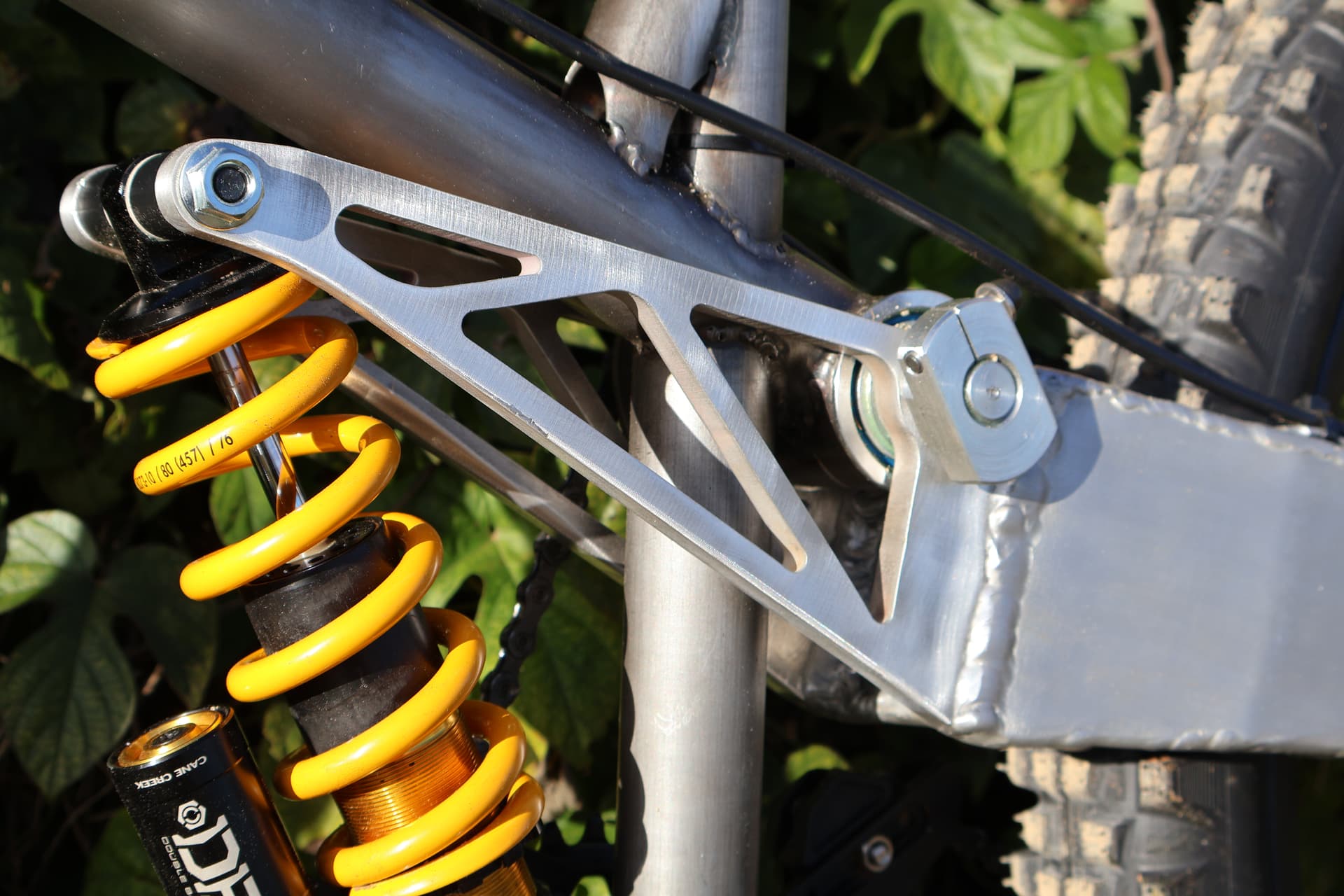
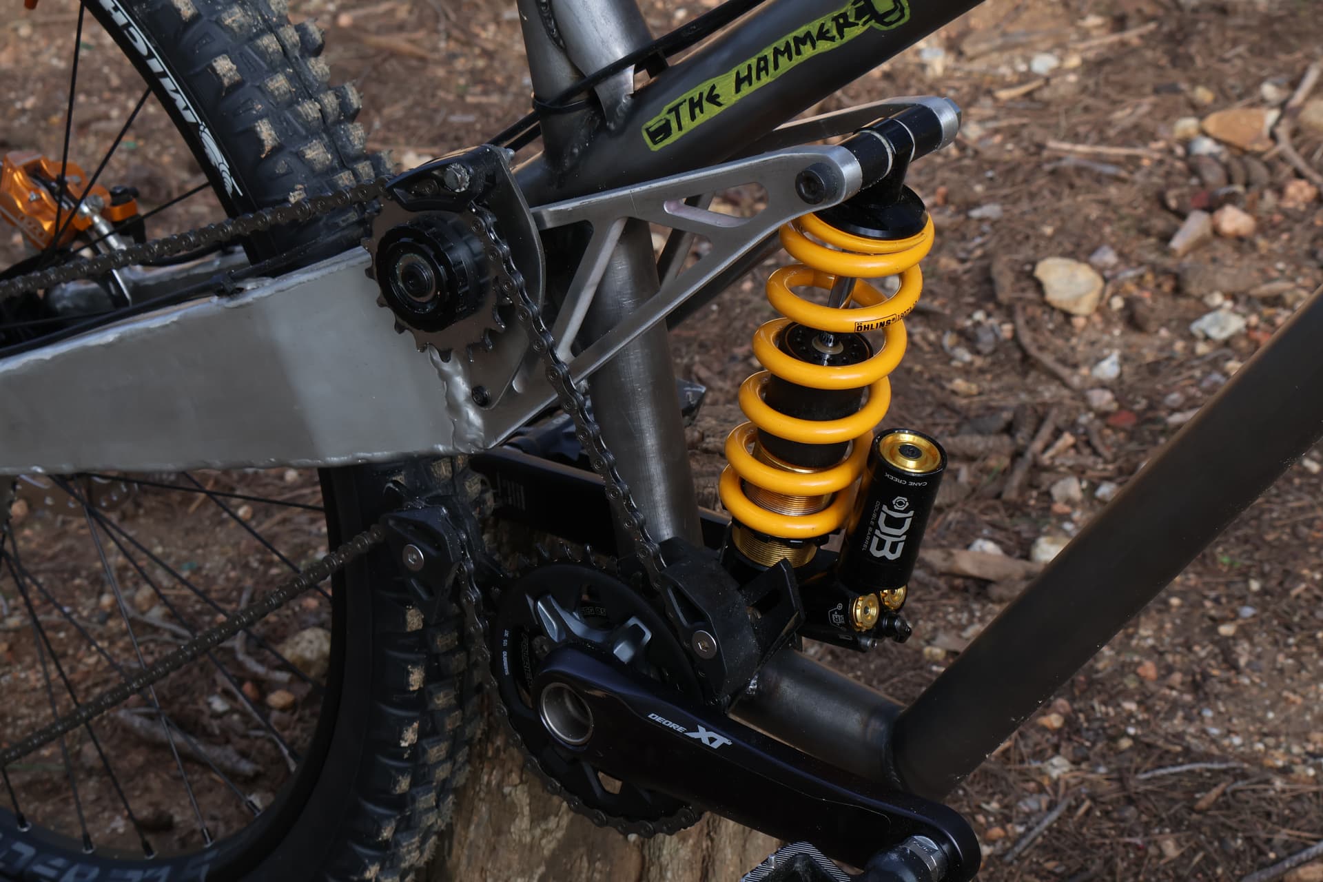
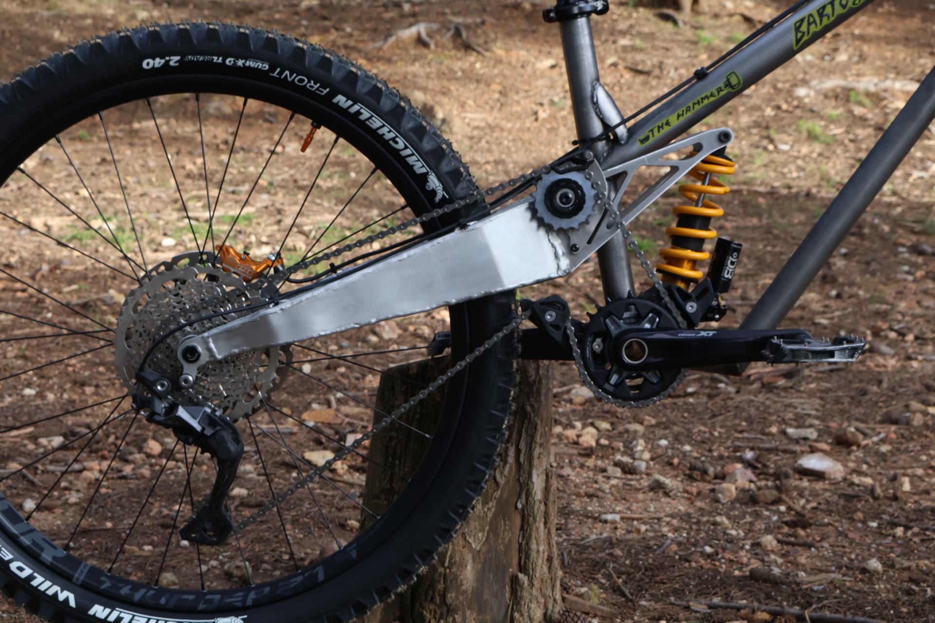
Ah yes… The Swingarm
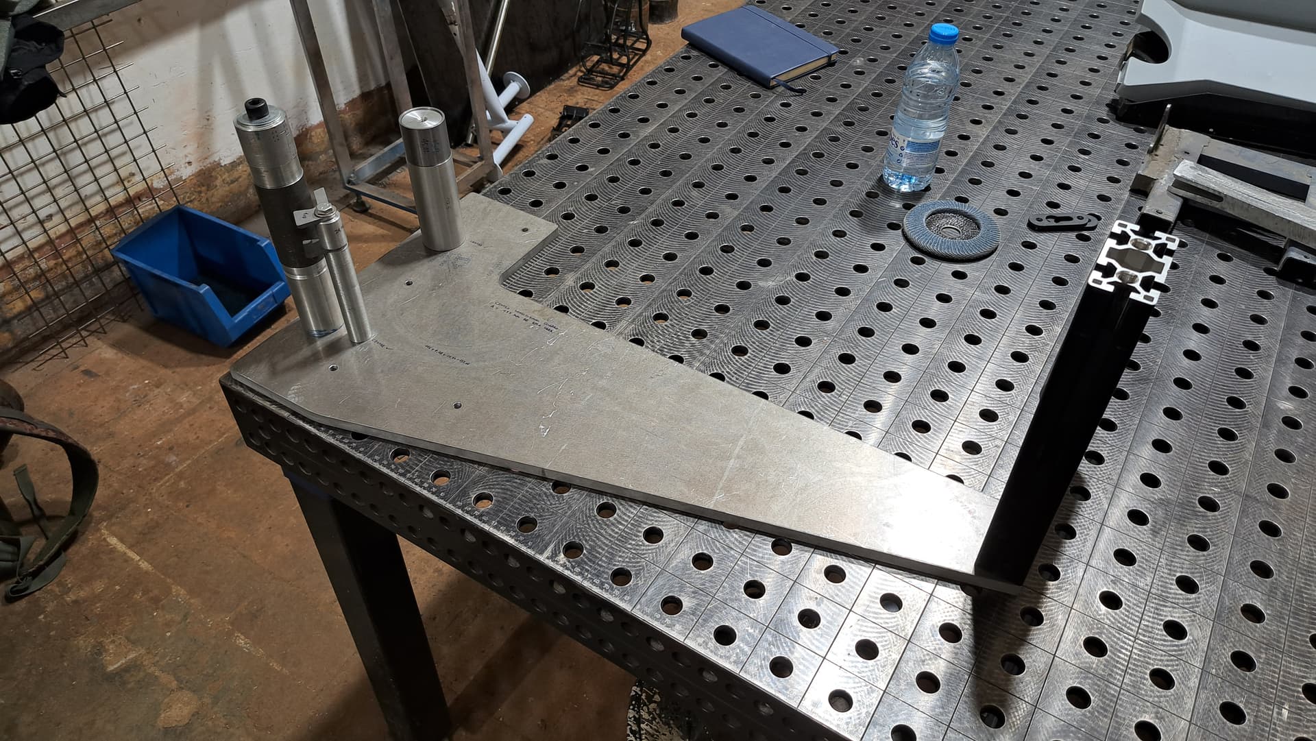
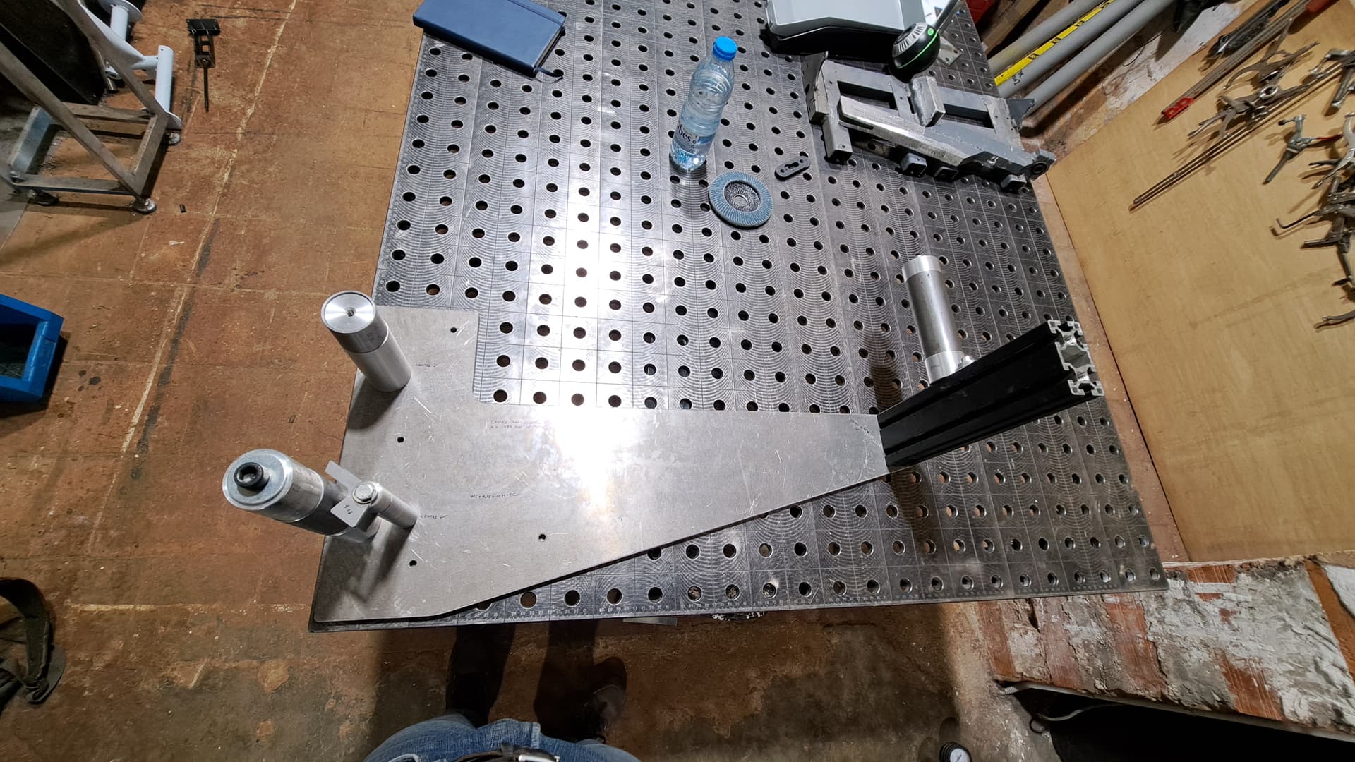
I was reading “The Racing Motorcycle Volume 2” by John Bradley, trully worth reading! and came around the 5xxx series aluminium. Doesn’t need Heat Treatment (my wallet loves that), only thing is you must be creative with it since it only comes in sheet, plate or round stock. I checked with my local laser cut supplier with whom i’ve been working for a couple of years and they have tons of this stuff for the Ship Building Industry. Got to work with the sheet metal design in Fusion and come to something which i like! it is also a little shoutout to my first dh bike, a Chumba Racing F5.
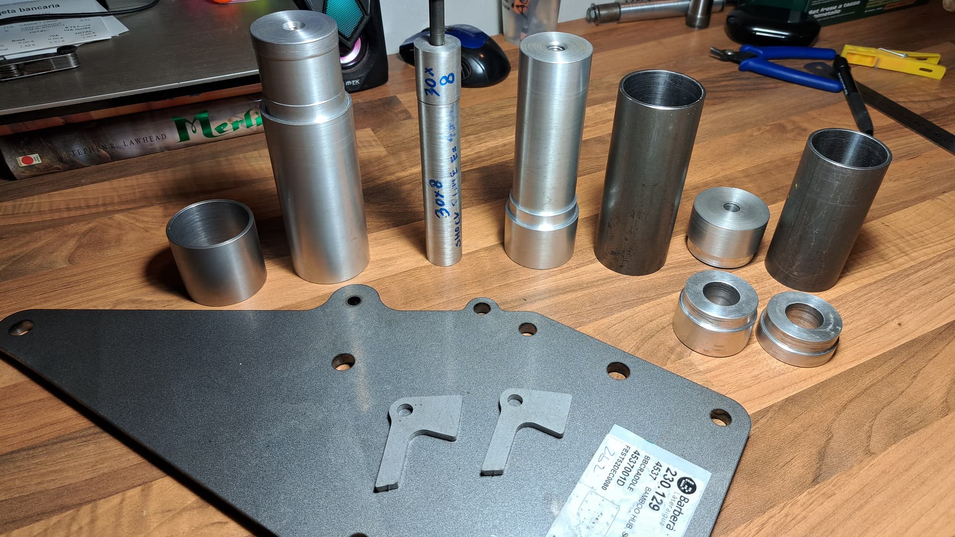
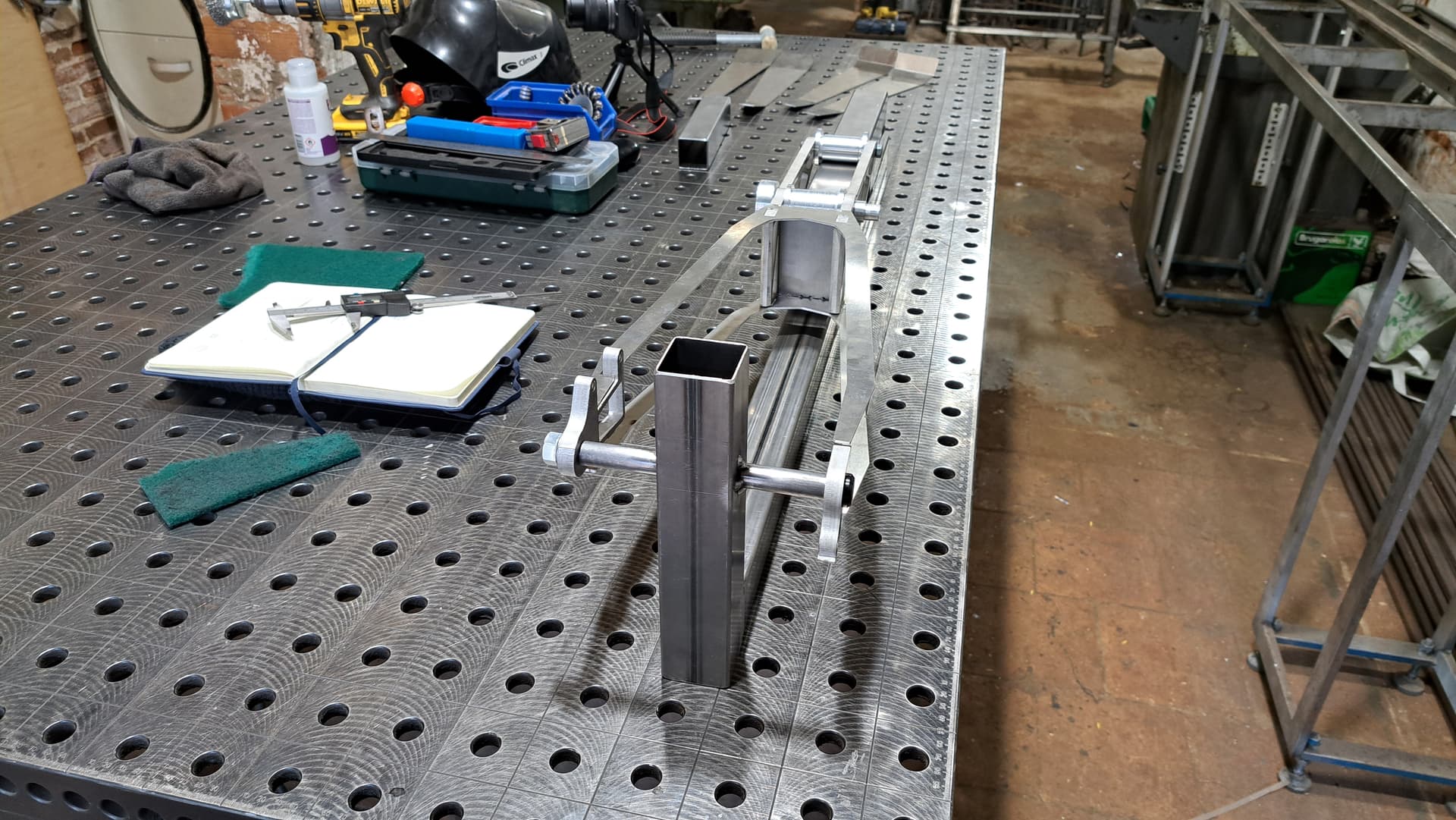
I am currently designing a One off adjustable Jig for future projects. Thought of doing a fixed coordenates one welding some tubes together but i prefer spending the extra time and design something that i will only make once and then insert add ons as i go.
Stay Tuned!
Kind regards,
Aleix Bartomeus