I wasn’t interested before, but now I’m gonna download the file because I use Fusion360.
1 Like
Nevermind I was able to convert it.
@crowe-molybdenum hey man, i’ve been looking for this exact type of drawing for quite some time now !
Long story short I’m in the middle of a career change and I will start a 3 years course of mechanical engineering / machinist soon. For now I’m only drawing bike parts for fun. And one of those parts is to adapt the square taper principles to a dub/bb30 axle and interface (within a t47 threaded bb shell).
I have a few questions, does your custom crank has a 30mm diameter or 28.99m Dub ?
also, on the drawings you showed from fusion, the splines are formed thanks to 6mm diameter circles, but the drawings posted before by PaulD show two different radius of 3.39mm and 2.61mm, so 6.78mm and 5.22mm respectively for the diameters of the circles.
It’s quite a big difference, are you sure the different bb30 cranks you tested worked without play etc ?
Also, how did you model the transition between the plain axle, and the thickest part of the spline interface (the end of the 11.1mm extrusion at 3° angle ?)
And last question, the angle is shown to be 3°, but should we enter a value of 6° since 3° is only compared to the horizontal x axis ?
I’m using Freecad, i’m not familiar with fusion so maybe these kind of parameters need some adjustements.
thanks a lot 
You should steal my idea for an ultra low Q factor track and/or TT bike that uses a T47I bottom bracket on T47/68 shell. Needs a custom spindle and crank however, and chain stay clearance will be delicate.
That would actually be my long term goal ! I don’t do TT but I would be interested by a track frame with such specs. Track and fixed gear frame have mostly been resisting trends and innovations, which is good thing IMO. The way people ride fixed gear it’s more important to retro-fit things rather than future proof. But for competitive Crit racing or proper Velodrome, I think this would make sense.
1 Like
hi amiroc,
Thanks for the interest, I’d suggest you get that file open, as it’ll explain how I’ve arrived to the outcome I have (the design history is in the file, and if pretty critical to understanding how the form is constructed). opening that file will also allow you to measure things in the first instance; fusion offer a free home use licence, and you’ll immediately be able to see exactly what I’ve done, and how.
Though in short ( ish) , I’ve used a 30mm spindle and 6mm radii at the specified section as described above. these radii can be difficult to measure on a real spindle, but ultimately, the measurements I took, and was confident in, disagreed with part of paulD’s drawing, this may have been due to non-terminal wear on the spindles;
if you take a section perpendicular to the axis of rotation, as that drawing has, at a depth of 6.10mm from the spindle , my two radii are ~3.32, and ~2.68 respectively, a difference of -0.07 and +0.07, as you move that section the radii change in an inverse linear relationship; they’re simply a function of where the end of the spindle is (or the offset of the section, depending how you choose to think about it) … thus, If you move that section from -6.1mm up to -7.4mm, my radii match PaulD’s drawing. screenshot here
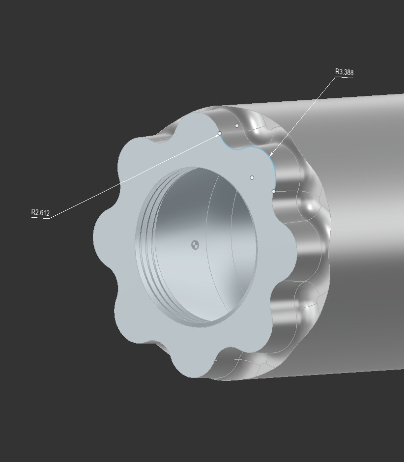
yet, my cranks don’t sit 1.3mm further inboard, nor outboard than expected; the taper bottoms out in the socket as designed and the cranks are measurable at the designed width when tight, both at the axle end, and at the pedal end; I’m taking those measurements on a B grade surface plate, and have high confidence in them; I essentially used these as verification measurements.
I’ve made two sets, and all the cranks I’e made have run well/zero play, all 4 mark up / transfer well when blued to check the interface on a spindle.
I’ve raced both sets of arms each on two different stock purchased spindles (one cannondale, one Stages) across a season of weekly track racing and training with no issues (~15 weeks of 2-3x per week) .
the transition is a simple single radius fillet (see file).
3 deg is measured in respect to the spindle axis, which is widely accepted.
I think my current takeaway is, if you think about where that ~1.5mm GOES when you do the crank bolt up until it bottoms out… this taper is VERY forgiving of the micron-level design and manufacturing of that interface.
1 Like
one thought you’ve prompted me to have, which I might need to delete in the morning, is that maybe this explains why the installation torque value seems so COMPLETELY FUCKING INSANE on bb30 crank bolts; mine all bottom out far before reaching recomended torque, and my sockets are all, quite notably, “larger” than the drawing Paul supplied… though that drawing doesn’t show the socket interface, only the spindle.
if it was my job to specify that torque value, I’d a) be dramatically under qualified b) be in the business of steel replacement bolts and c) make the recommended torque through the fucking roof, so when someones spindle is “oversized”, the crank still bottoms out before it cracks, and then the torque stretches the bolt the “right” amount, without over-stressing the crank arm… (?)
thank you for your thorough answer, if you have the time could you re export the file as a STEP ?