this hasn’t stagnated, its simply been moving at egypt - speed.
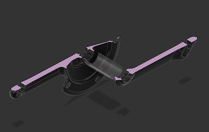
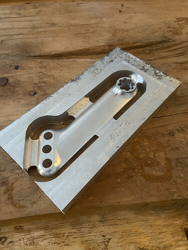
I received back (from my newly discovered local ‘guy’) a test part!
some good learnings.
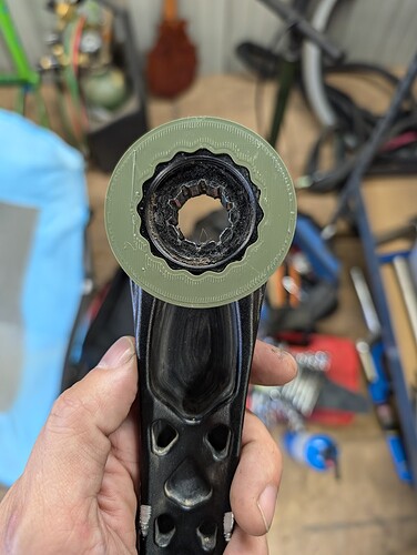
first up- the splines.
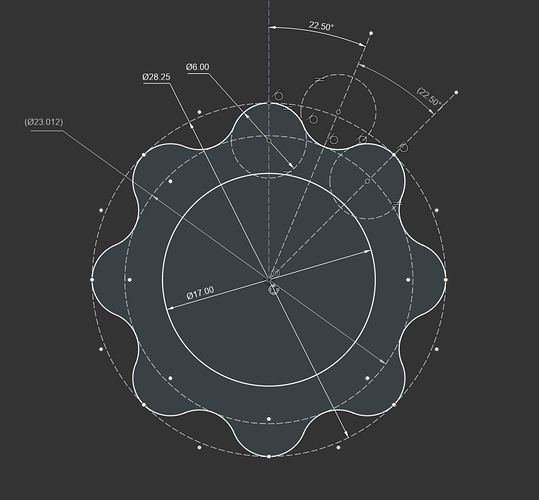
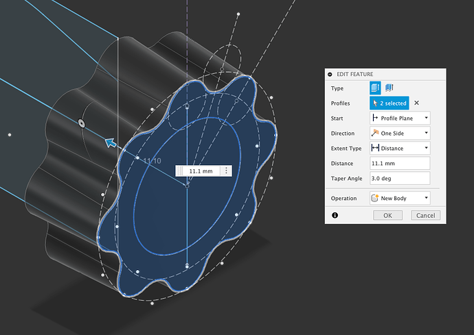
the splines on this part are cut from a drawing I created by balancing the above contributions, measurements I took from the 3 bb30 cranks I could get on hand (all cannonade branded) and measurements I asked of a trusted friend who also had a crank on hand. (shoutout David at Goat Cycles Christchurch).
the splines created here are measurably the same depth as the drawing.
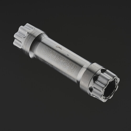
when they push onto a spindle by hand, they go on the same distance I would expect from the drawing, leaving an mount to “do up” which is very similar to (/within the range of/) all the other cranks I could get hands on. when done up to an array of torque numbers, they move onto the spindle very similarly to the other cranks I have on hand, and they end up bottomed out in the same position, at the recommended torque.
if I colour in the spindle with a sharpie, and install the crank arm, it takes a reasonably even pattern of about half the sharpie off.
so I think i’m pretty happy with that. enough to press on and try them IRL anyway.
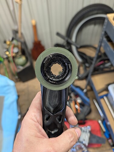
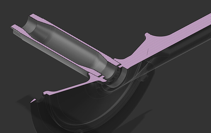
next up; the extractor cap threads.
SO, I naively measured ONE set of extractor cap threads, and presumed they were also a defacto standard.
they are not.
upon further investigation m25x1.0 is in use with 18mm bolts (some cannonade/fsa bb30) , m26x1.0 is in use with 15mm bolts (mostly gxp) , m30x1.0 is also in use with 18mm bolts. (most sram dub/bb30)
I initially measured the threads at m25x1.0 at a ~6m depth. so thats what I called out on the drawing, the machinists duffed this thread, leaving a ragged ~25mm hole so I pondered increasing the size, for the sake of this test, and googled it. at this point I discovered m26 and m30 options so I asked him to increase the size to m26, thinking I could make a custom extractor cap and use the cannonade bolts I have on hand.
he then duffed the m26 threads…
so i’ve been removing this crank arm from the test spindles with a gear puller…
but I think anyone designing cranks going forward likely wants to use the m30x1 option, so as to make sourcing (both original and replacement) bolts and extractor caps as simple a possible. the m25x1 does appear to still be in use, and this option could be nice for its smaller size requirements in some cases.
(NB: opinion: these bolts break in time with normal use, I think the listed torque is unnecessary)
pedal threads;
I couldn’t find any 9/16x20 taps at all here, let alone a L&R pair, so i’ve ordered them from overseas, and will likely end up cutting these threads by hand after the fact. ill make some sort of block or machine setup arrangement to get them square.
the taps are now on the way, but out of interest, on paper M14X1.25 ( much more readily available tooling in my neck of the woods) is pretty close to 9/16X20. I know people have used m14X1.25 taps to chase 9/16 pedal threads, as nervous as it makes me  . and I know I could test this very easily, but I’ll ask anyway. has anyone here MADE a, m14x1.25 thread and put a 9/16 pedal in it?
id LIKE to say it shouldn’t fit…
(yes I know this is also an old French pedal thread standard)
.
![]()
