Hello CFF community! My name is Brendan of Cal Poly Bike Builders Club, and I’m stoked to share my finished cargo bike with you guys. The Brendanmobile is a cable-steered, front-loader cargo bike. I fabricated the rear half of the frame using my club’s Anvil jig, and I 3D printed fixturing for the front half. I manually machined the cable steering pulleys and front dropouts in my university’s machine shop, and my seatstay yoke was DMLS (direct metal laser sinter) 3D printed in China.

Since I would be working out-of-jig for the front half, I started fabricating from the back. I’ll probably build all future bikes this way, with the best welding access for the hardest welds (chainstays and seatstays). As a mediocre TIG-er I needed all the help I could get. I’m stoked on how the seatstay yoke turned out, especially for the price ($40 with shipping, pre-tariffs). The embossed letters could end up causing stress concentrations, so I’ll report back after a couple million load cycles. Since it’s a cargo bike I don’t expect to be hucking anything crazy, and unless I’m transporting a buddy the bucket payload is usually pretty light.


Welding frame up to the rear (aft) head tube was straightforward thanks to the Anvil jig. The downtube to aft headtube joint was the only tricky part; thanks to the hole saw runout I had extra thin walls on the sides of the downtube.

The front end was where the fun really started. I used my club’s Cobra Toob Bender to bend the bin rails, which needed 65-degree and 80-degree continuous bends. Since the Toob Bender has a ~30-degree bend range, I achieved these larger bends by bending a couple degrees at a time and creeping up the tube. This took forever but the bends turned out well, with no kinks and minimal lumps.
One flaw of my custom fixture was the static reach on the front head tube. Had I been able to move the front head tube forward or backward, I would have needed less precision on the bends (the least precise fabricating procedure with my equipment). I ended up getting the rails to intersect both head tubes, but the straight sections differ in width about the bike’s centerline by about ½”. Living and learning! And laughing and loving!


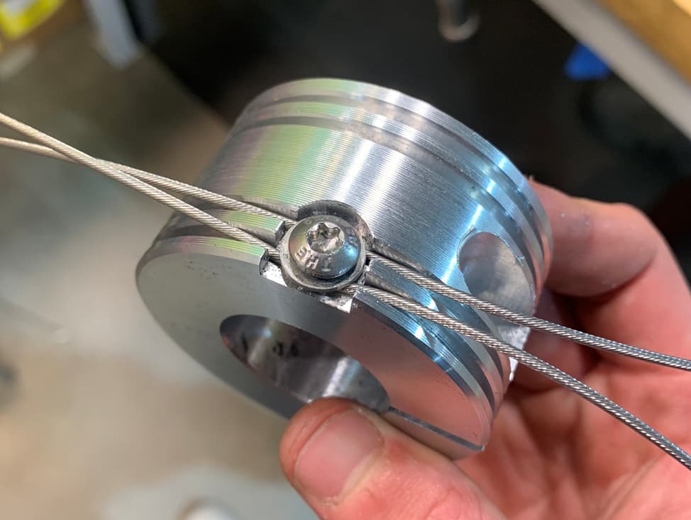
With the frame welded, I moved on to the cable steering system. Credits to Phil Vandelay for major inspiration on the cable steering puck design. Check out his video here: https://www.youtube.com/watch?v=AqCKsRxyX0A
One thing I plan on changing for the next iteration of my pucks is using cable knarps to secure the cables, or one bolt per cable. Two cables sharing a bolt makes initial tensioning much more cumbersome. I’ll also replace the collar style bolt with a more secure steerer tube attachment method.

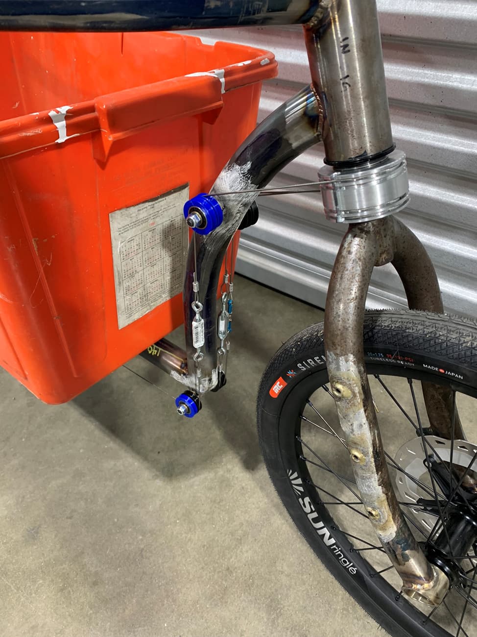
I decided to use pulleys instead of cable housing in my cable steering system for a smoother steering experience. To attach the pulleys to the frame, I fillet brazed shoulder bolts that matched my bearing’s ID to the front downtube, managing to line up the cables by eye without any fixturing on the first try. Turnbuckles are used to adjust cable tension.
The cable steering system is pictured below with PLA idler pulleys, which I eventually machined out of aluminum (although the PLA pulleys survived a ~100 mile bikepacking trip before replacement).
Using some mystery stainless steel I manually machined the front dropouts. I used the mill + rotary table for the hub relief, which was the perfect tool for the job. I’m very pleased with the surface finish I obtained on the stainless. I found a fork at the Bike Kitchen (local bike thrift store), bent the blades with the cobra bender, and welded on my stainless dropouts.


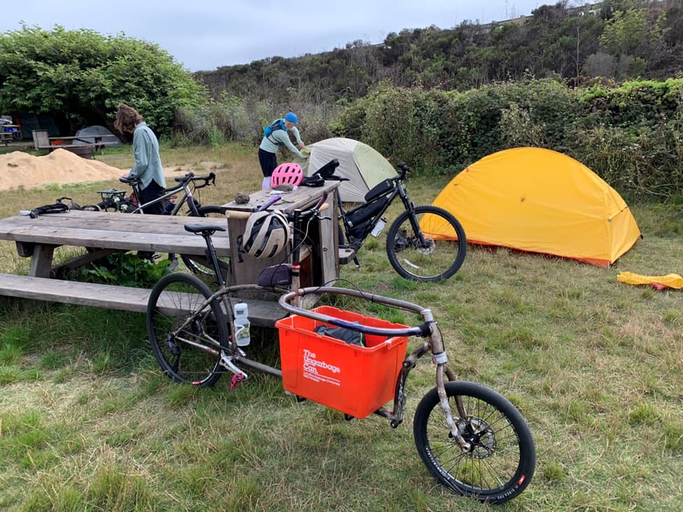
The head badge was the icing on the cake, as this bike is the truck of my bike fleet. The bread and carrot are copper, the cheese is brass, the milk is stainless, and the truck is carbon steel. Planning on allowing the truck to get a patina of surface rust. I’m happy to report that the bike carries groceries just as advertised!


Mostly all done! Future work will include a second version of the cable steering system (knarp city), a better kickstand mount, and a custom fiberglass bin with a locking latch. For the last several months, the Brendanmobile has been holding up as my trusty little truck!