Hi!
As I’m looking at those pics - which I like by the way - some questionmarks pop up in my mind.
- Did you already choose a fabrication method? Because, for what I know, SLM and CNC require different design strategies. For example those “stubbies” with the inner tube are nearly impossible to manufacture with metal cutting methods. But on the other hand a bearing seat in SLM would require post reaming because of heat distorsion.
- Are you aware about the costs of those methods? You could just send a file to a manufacturer (PCBway?) to get an idea.
- Are you sure those advanced technologies are the right way to achieve your goal of having a ridable prototype of your suspension design by next summer?
- Is it maybe better to learn how to TIG weld and create a design based on lasercut sheet metal (affordable/simple/quick/available) and tubes (round/rectangular)
For a first frame, and for design prototypes in particular, I like the phrase:
Don’t make it right, just make it ride!
-Thom
1 Like
Hello,
I appreciate the feedback. I have listened to your concerns and have thought about my approach at building the bike.
I am still trying to decide whether SLM or CNC will be better for my application. Also, I am aware of the costs of these methods and I am looking at the cost of 6061 vs 7075 on PCBway like you suggested.
Also I like using lugs as opposed to welding. First, I have no welding skills and I don’t feel I would be able to build a frame with the precision that I need in order to make the frame. Secondly, I have access to 3d printing in order to test lugs and make sure the fitting and suspension movement is perfect before I send them out for machining.
As for the phrase, “Don’t make it right, just make it ride” I am sadly too much of a perfectionist for this approach 
For an update on the progress on the frame. I completed a model of the bike and started to run stress simulations on it. However the simulations have shown that I need thicker tubes than the ones that easy composites offer. I have also done some more research on pivots and I took apart on old salsa rear triangle I had laying around to get a better idea. With more knowledge on pivots and the knowledge that I have to remodel for thicker tubes I started a new CAD model using the same base parameters but with fixed pivots and tube dimensions. I try to do a photo dump in a few days of a few updated lugs and pivots.
Is there anyone that has any experiences with buying carbon fiber tubes in the US for a lugged frame application and have suggestions of tubes or brands that I can use? I’m open to any feedback.
Thanks,
Pioneer Cycles
1 Like
Hello,
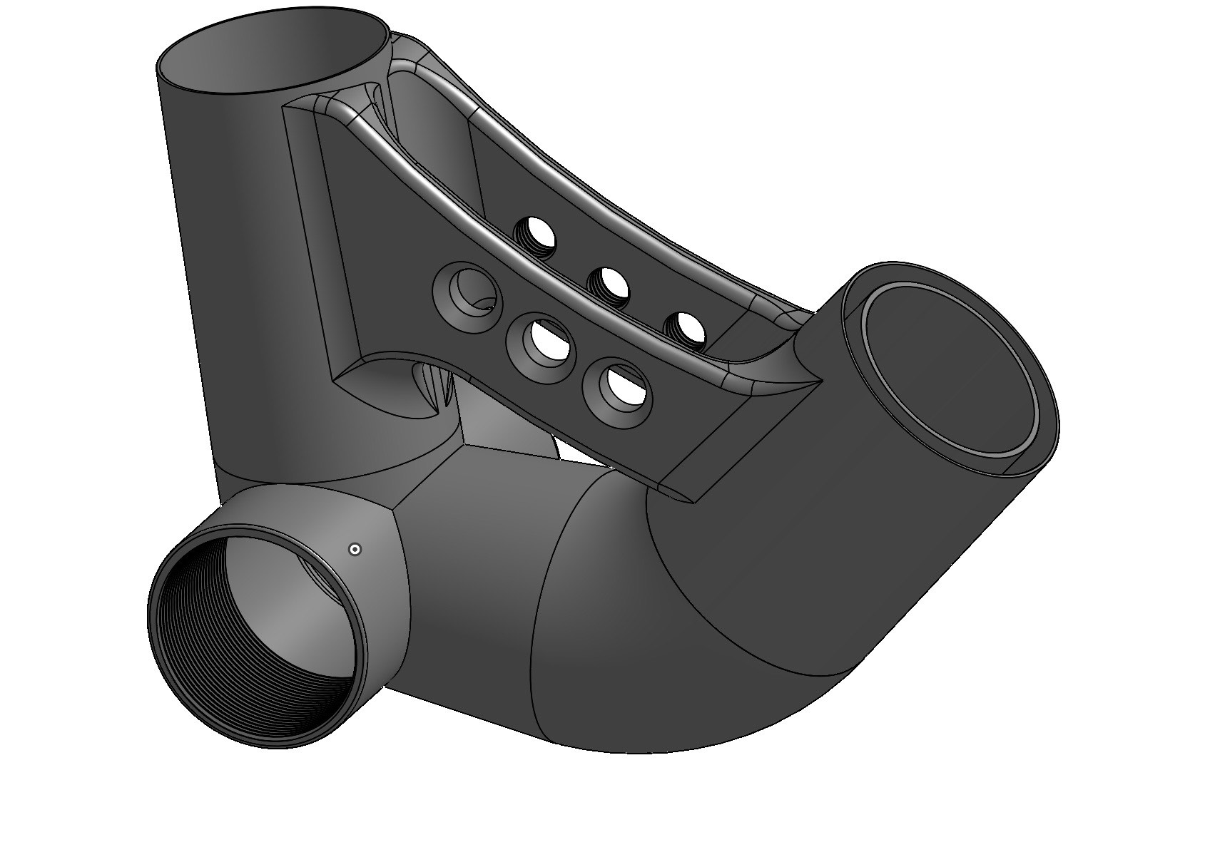
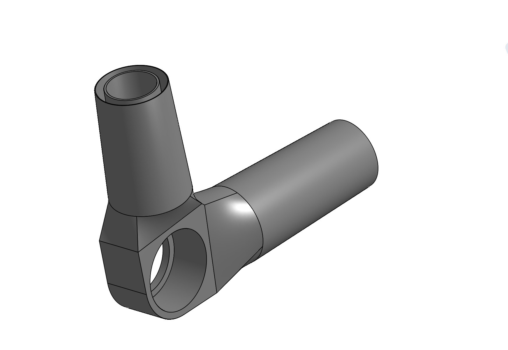
These are some photos from what I have been working on today. I got the pivots remodeled and I think that I have figured out what I am planning on using for the tubes.
All roll wrapper 3K carbon fiber tubes:
DT: OD 40mm x ID 34mm
TT: OD 38mm x ID 34mm
SS: OD 22mm x ID 18mm
CS: OD 25mm x ID 20mm
7005 Aluminum Tube:
ST: ID 31.8, 1.1-6-9 Ext. Butt Seat Tube
Let me know if you have any suggestions.
2 Likes
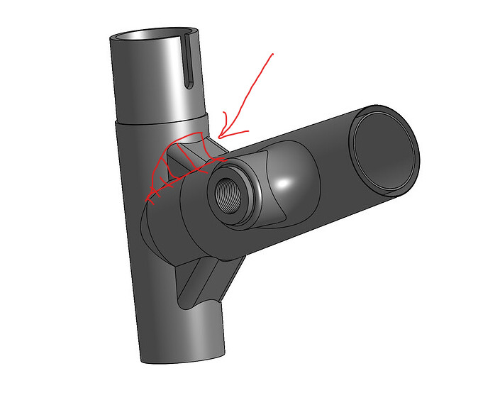
Since you are printing these, why not go for a big fillet where you have the little ‘gussets’? Are you wanting the look of these pieces with the more mechanical lines? Just double check your clearance around the shock eye at that bottom mount across a few different shocks that could be used.
2 Likes
Hello,
I appreciate everyone’s feedback. I haven’t posted in a bit. I have continued working on the frame, and have made some big progress in the model.
I am curious if anyone has a STL. file or link to a CAD model of an IS brake adapter for a 203mm or 200mm rotor size? I need this in order to check that I have modeled the IS brake mount correctly.
Thanks for everyone’s feedback, it helps a lot with designing the frame.
-Pioneer Cycles
Hello,
I have been reconsidering my approach to building the frame which I have been designing in CAD. I am starting to come to a point where I am happy with the layout and geometry.
Next steps in the process is to model lugs for the front triangle. I plan on 3d printing and sizing these appropriately for PVC pipes. This will enable me to confirm my estimates and ideas about the suspension system I’m designing.
I am also looking at designing at the rear triangle of the bike out of carbon fiber. I have done research into 3d printing molds out of a filaments such as PETG. This approach will in theory allow for the rear triangle to be made more cheap than machining the rear triangle as a single aluminum piece. However, the downside of this method is that I have no experience with working on carbon fiber.
For the front triangle, I plan on having it welded. I don’t have experience with welding and I would need for help with this part. I have a CAD model of roughly what I want (minus mounting for an idler- I can’t figure out how to attach effectively). Does anyone know someone or be able to help me with this, in the New England area.
Thanks,
Pioneer Cycles
1 Like