I am a high schooler who is in the process of designing a custom enduro bike in CAD. The goal is to have a functioning bike by next summer in order to test a suspension system that I designed.
I was originally looking at building a welded frame, but having many pivot locations brings in the concern for accuracy. So this has brought me to the idea of building a frame using either 3D printed lugs or CNC machined lugs. On top of that, using lugs allows me to use carbon fiber tubes to keep the weight of the bike down.
I currently have just started my fourth CAD model of the bike on OnShape and am trying to figure out some of the specs of lugs such as recommended overlap length and how I should let the excess adhesive escape the system.
I am new to frame building so I’m curious if anyone has any suggestions or concerns about building a bike this way?
I’ve built a couple of frames with CF tubes glued into lugs. I made the lugs in the first place by welding bicycle tubes (mostly head tubes) together. Only the TT and DT were CF. I just made a conventional steel rear triangle.
I used MMA glue on the suggestion of the people who supplied the CF tubes (easycomposites.co.uk). The strength of the glue per mm^2 is on their website so you can estimate how long the overlaps need to be (and add some safety margin!) Note that if you make them too long, it can be hard to assemble the frame: you’re relying on a little bit of flex in the CF tubes in order to get it together. Make sure you can do that “dry” before covering everything in glue so you know what the best procedure is.
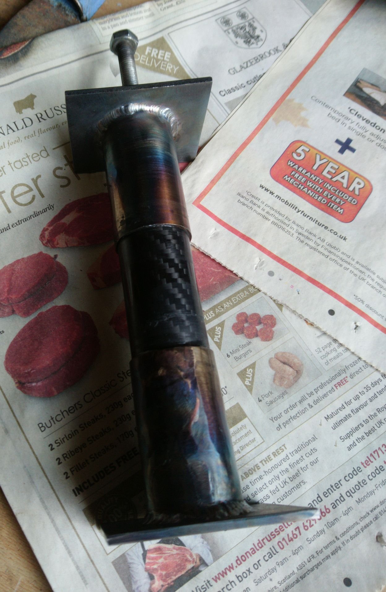
I mitred the CF tubes so they would theoretically go all the way into the lugs, and then I sanded out the insides of the lugs using 80-grit emery wrapped around a bit of aluminium on a drill, to get the right kind of slip fit, and lightly sanded the CF to take the lacquer off. I made this test rig to make sure my gluing procedure was actually going to work. The bolt is pressing against a capped steel tube inside the CF one, and there’s a captive nut welded onto the top plate.
The diameter of the CF tube here is 30mm, so as you can see, the lugs are about a couple of inches long.
The first time I tried it the glue failed and it just came apart scarily easily when I tightened the bolt (!) After a bit of experimenting and peering at things I figured out the problem was the fit was too tight so basically all the glue was getting pushed out. With a slightly looser fit and putting the glue on both surfaces (the instructions said just to put it on one, I should never have read them) I got a good joint. The bolt sheared off after about 4.5 turns. Since this was an M8 8.8 bolt, the force should have been north of a couple of tonnes. I broke another two bolts in there and then resorted to whaling on it with a hammer. The CF tube itself is what broke eventually.
So 2” of insertion is probably a bit more than what you need. But the biggest eye-opener was how much it sucked on my first attempt due to the fit being too tight. So I highly recommend doing a few tests like this to get your procedures dialled in before assembling the frame.
Both bikes have now been in use for a few years with no issues (although it’s possible galvanic corrosion will be a problem eventually).
Mine were made out of Columbus Zona head tubes, because they had about the right ID I needed for those carbon tubes, and were plain-gauge. I mitred and welded them as if I’d been making the whole frame out of metal (I tacked lengths of mild steel tube in where the carbon was going to go, so I could jig the whole thing up as normal, and then cut those out right at the end before gluing in the carbon).
But people often do use CNC or 3D printing. I don’t think either will be as good metallurgically as welded cold drawn seamless CrMo which is what those Columbus tubes were. But either is perfectly good enough, and lots of bikes are made this way.
I hadn’t thought of this way before. I haven’t welded before except for 30 minutes, so I don’t know how well this approach would work for me.
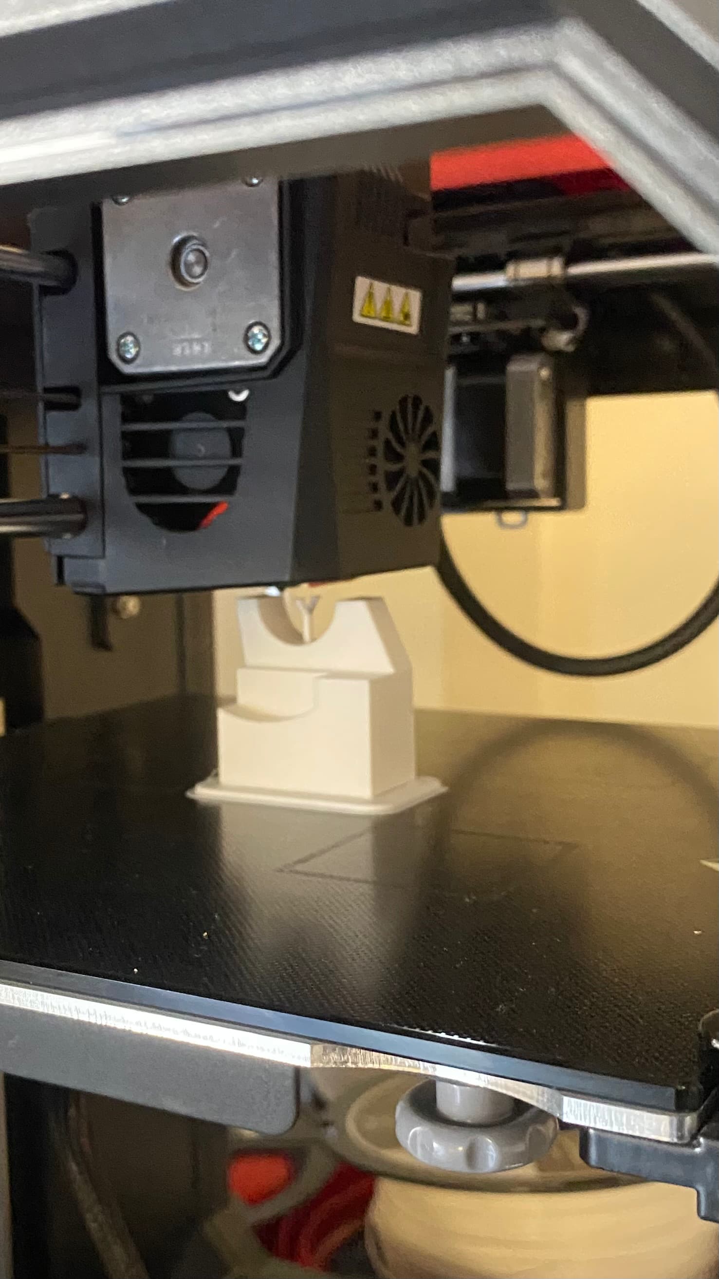
I have access to a 3D printer which I can use for prototyping if I go with the CNC or 3D printing approach. I’m thinking that I will do ridge style lugs like what Atherton has done.
Another thing I was thinking about is using a dropout for the UDH mount, but I’m not sure the best way to approach it.
Yes, I normally just make welded steel frames. But this guy wanted a CF/metal hybrid as he remembered those bikes from back in the day (it takes all sorts). But he was letting me build him a bike so I wasn’t going to complain
But I think it’s quite an accessible way for a hobbyist to make a frame these days if they know about CAD and 3D printing and things, which it sounds like you do (but might not have the experience with welding). Whereas I already could weld and had a welder. So it’s just about using whatever you have.
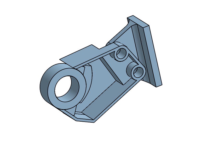
Working on printing my second version of the UDH derailleur hanger mount, does anyone have any suggestions of how to make it attach to the seatstay/chainstay lug?
In my early model I made it so that it attached by bolts, but I can’t figure out how to transfer from the seatstay and chainstay holes to the bolts which attach the the UDH mount as in my last post.
Would you like to share a picture of a complete model of your bike so it’s easier to imagine good solutions to your problems, for example, we don’t know if your suspension layout requires movement between CS and SST in relation to each other. Why do you want to bold the UDH mount to the frame and not integrate it to the CS/SST lug?
I appreciate the feedback, I designed the suspension system from the ground up, so I am not able to share the system yet. However, I will say that it utilizes a unified rear triangle.
I have been thinking about having the UDH mount bolted to the chainstay and seatstay lug because it allows me to change the chainstay length and mess with the geometry after the build is finished. I am open to trying building one lug that connects everything.
Any help is much appreciated because I am new to building bikes.
You could take a look at these dropouts and try to utilize the same hardware. When starting out or learning something new, it’s often easiest to find what someone else has found to work and build upon that to get to the solution you’re after.
Thank you for your feedback, I am looking at trying to build a dropout similar to the one that @Dr.Hossa sent me.
I like how that dropout still bolts to the frame, but it seems like a much simpler design to what I previously had modeled. It could pretty easily bolt to the chainstay/seatstay lug.
I’ll model one similar to that one this afternoon and see how it works with the design.
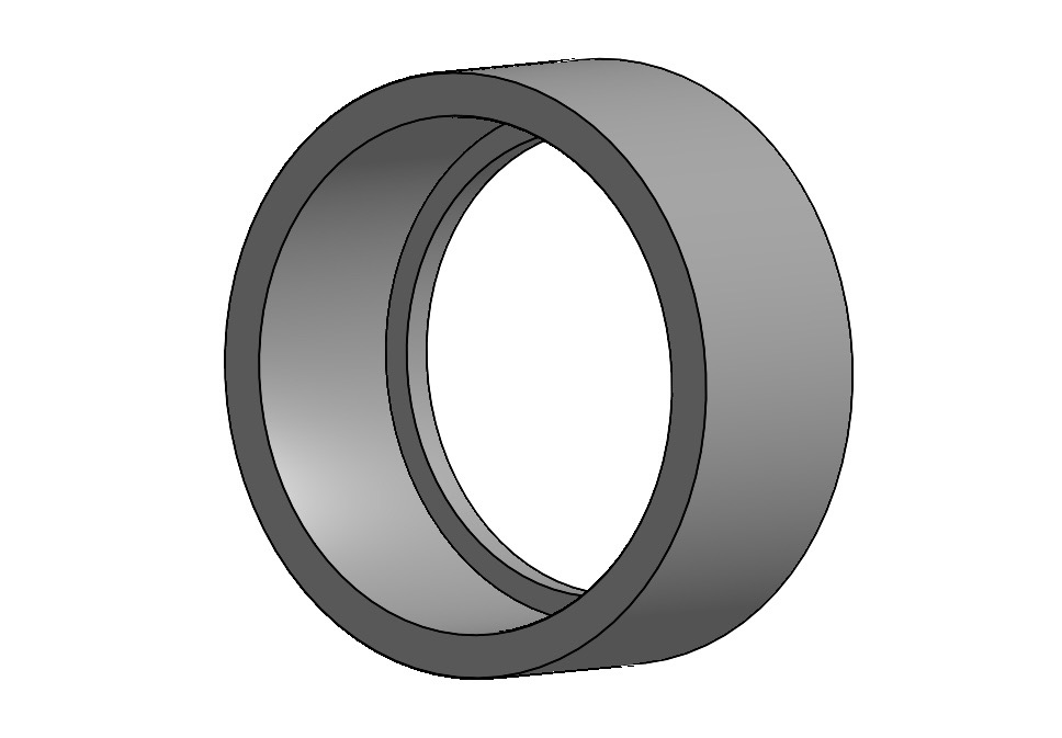
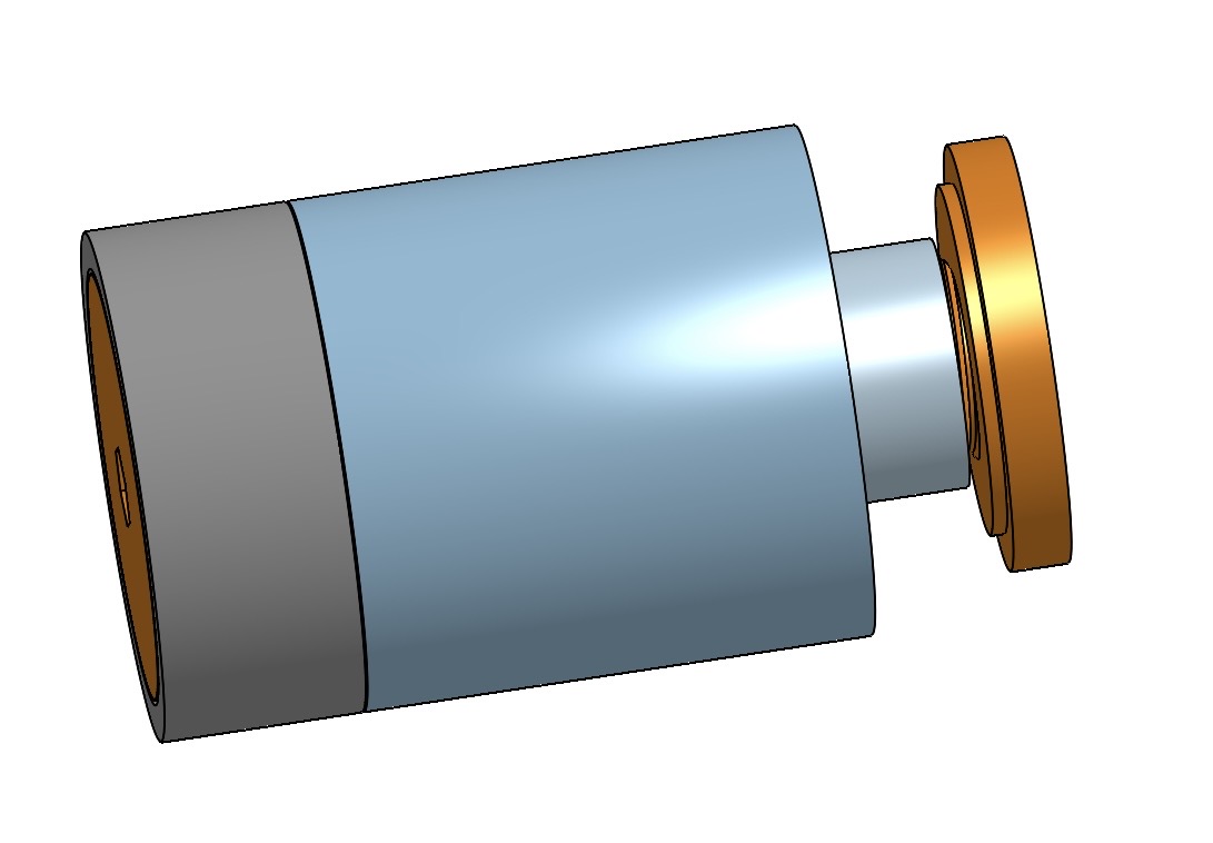
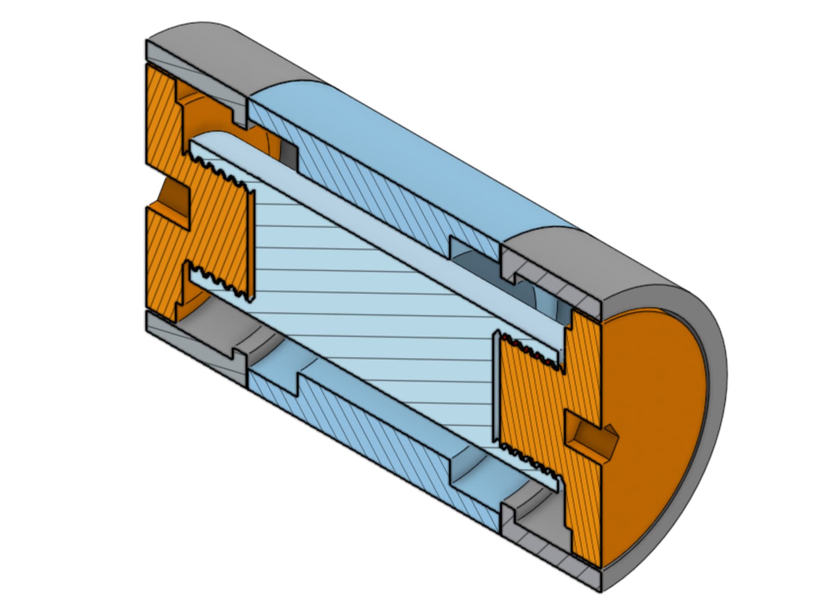
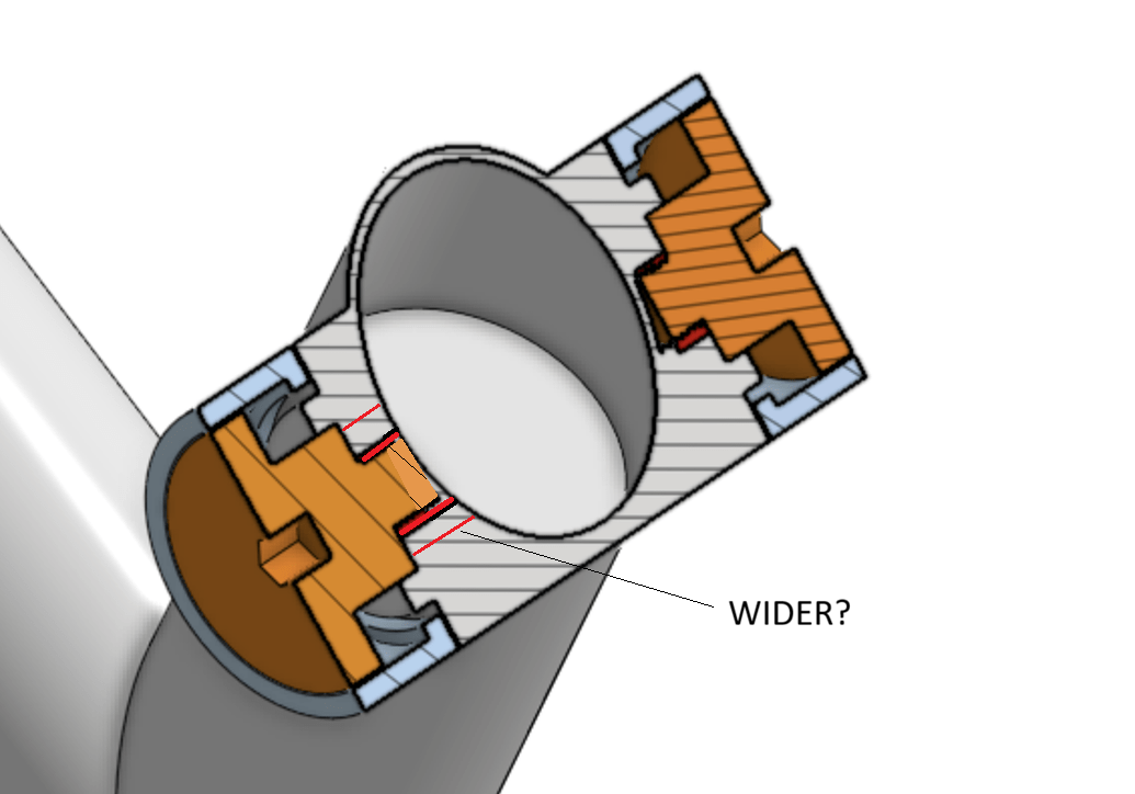
This is an updated photo of the bearing housing. There are two bearings in the middle housing and one on each of the sides behind the bolt. They are going to be connected by washers.
I don’t see a situation were I would use a bearing setup like this but we don’t know your suspension system yet. But I’m quite sure you will need a shoulder on your axle to stop the inner rings of your bearings from being pushed to the middle when tightening the bolts.
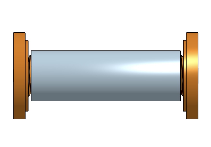
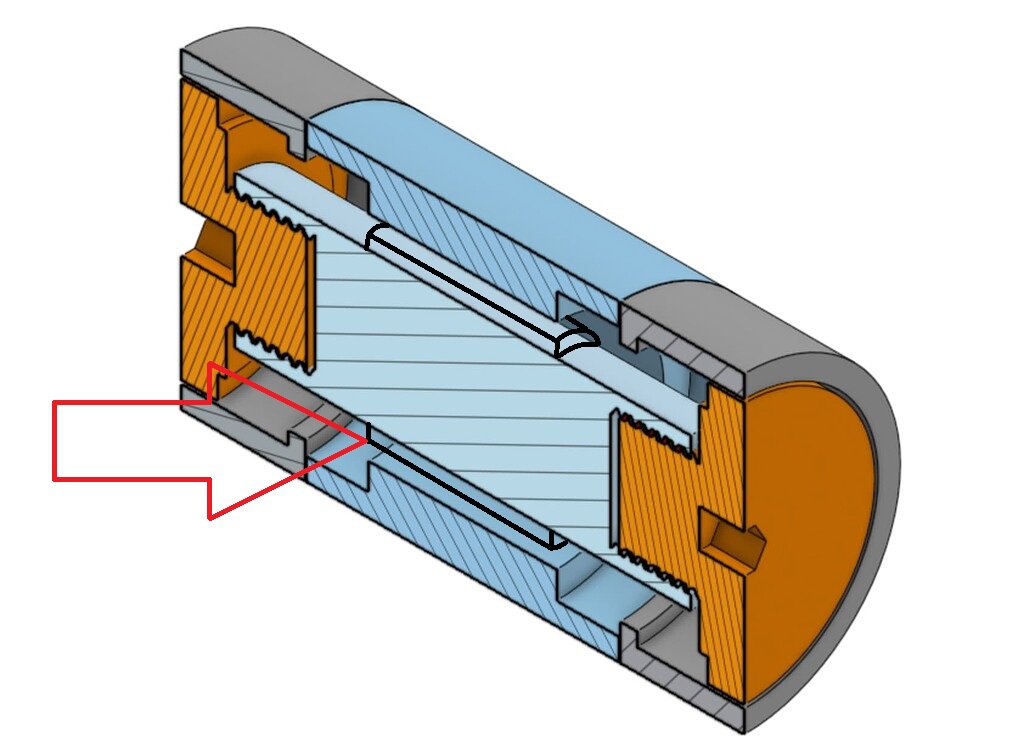
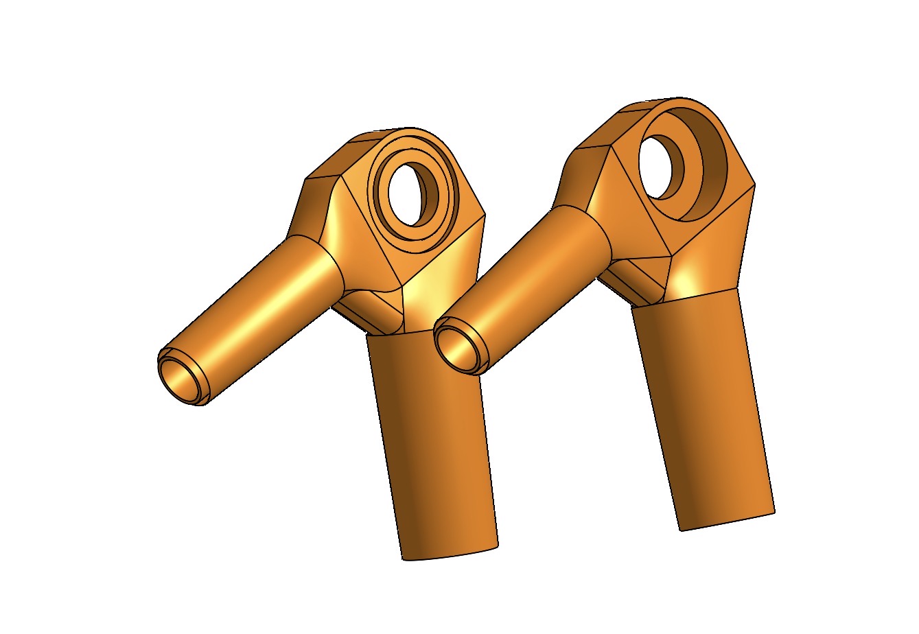
Thanks for pointing that out. I really appreciate your help. I think fixed the bearing issue, and made it easier to torque, but I’m struggling trying the figure out how to build pivots.
The 2nd pivot assembly does look good. Only the thread should go all the way through the lug to get more “meat” for the bolt. What’s the inner Ø from the bearing 15mm? Is the thread M8? You could make it wider. M12x1.25 maybe.
The new version of the more complex pivot assembly doesn’t solve the potential problem I pointet out and it will be terrible to make. You could take the version before and add a long spacer between those inner rings.
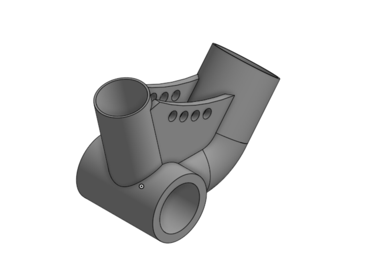
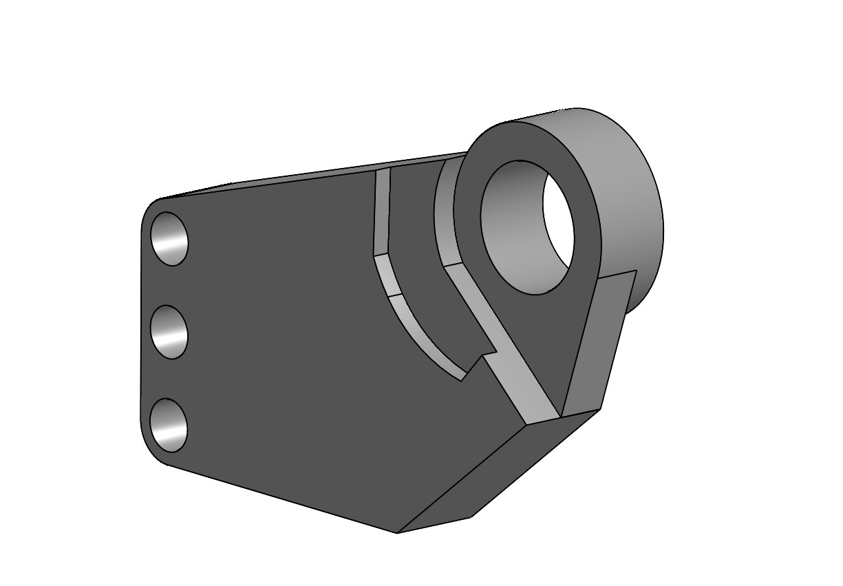
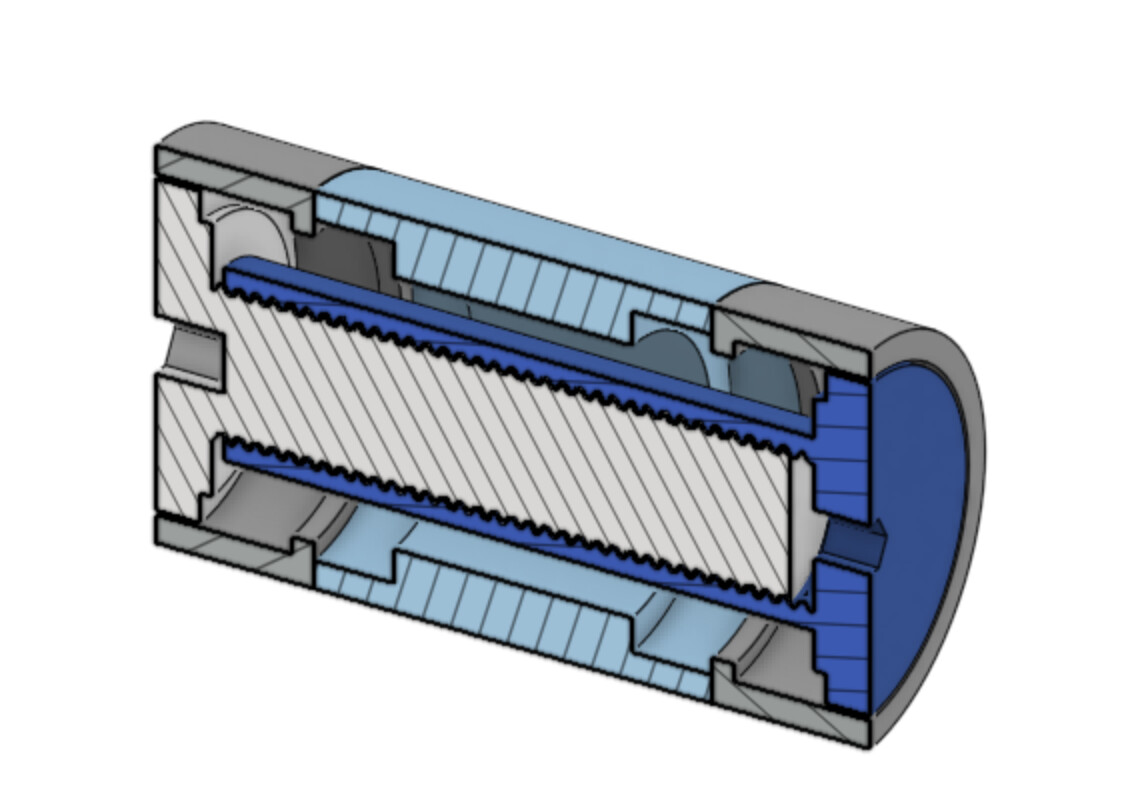
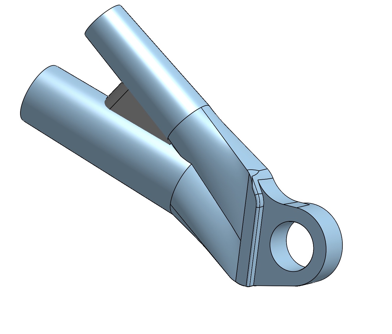
I haven’t posted in a while. I’ve been working on my CAD skills over the last week and I have been able to start remodeling the lugs in a way that look and function better than the previous version.
I added a support on the inside of the tube like what Atherton has done. I also removed the UDH dropout in order to have a stronger connection and to keep the weight of the frame down.
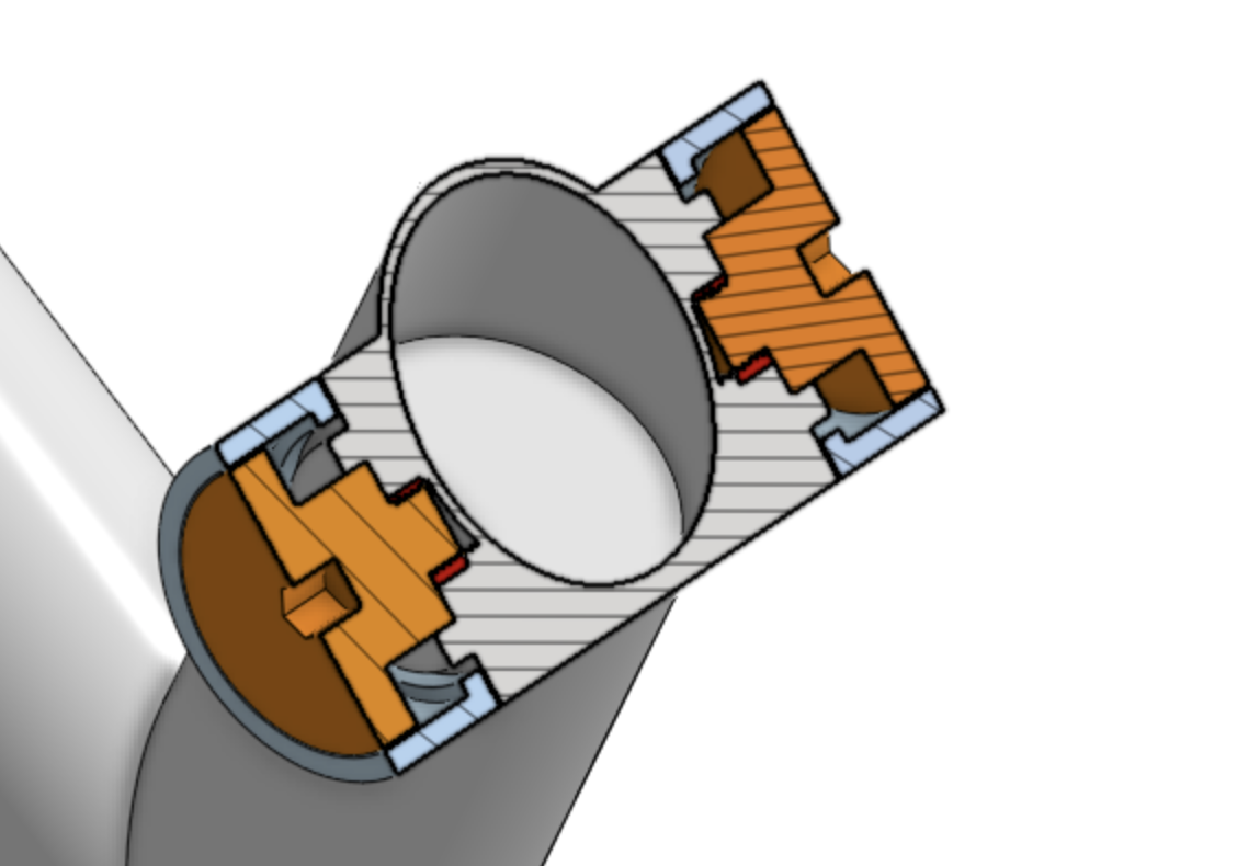
I am still working on building pivots that I am happy with, but I feel that I am starting to settle on a housing that I am confident with.
Another thing I am considering is how cost effective it would be to have a support between the top of the seatstay lugs and how to build it in a way that it isn’t all machined in one piece.
I appreciate all the feedback, and am always open to suggestions.