Building a lugged fork - share your process

Hi All,

For my next frame, I’m thinking of building a fork with a standard lugged crown, and realizing I’ve never done this before. I would love to know your sequence and thinking on how you got to the steps you take. Mostly related to the steerer/crown/legs. I don’t really need any pointers on the dropouts unless you have a really innovative way of approaching those.

For background, I have built maybe 15 forks so far, over the past 12 years of frame building. I have built segmented, twin plate style, and a few with the Cinelli style internal lugs, where I sweated the brass out from inside to ensure penetration. All were built with brass, actually. I’m open to silver, though.

So please share your process. Do you pin? Do you do the steerer/crown first?

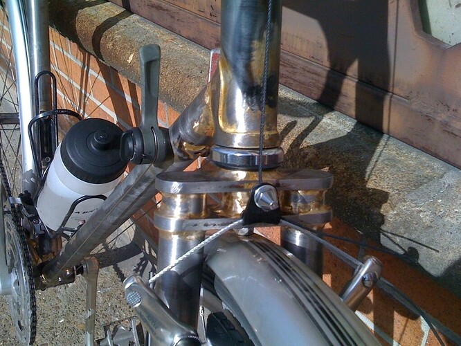
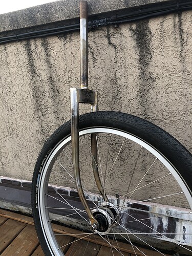
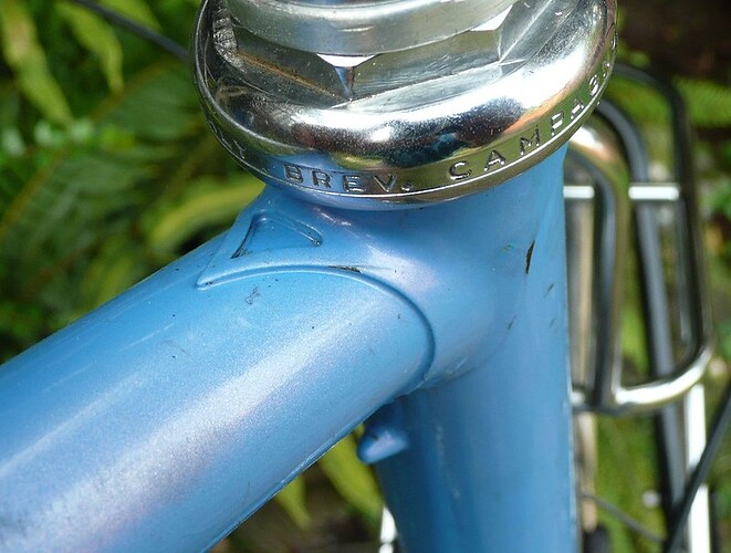
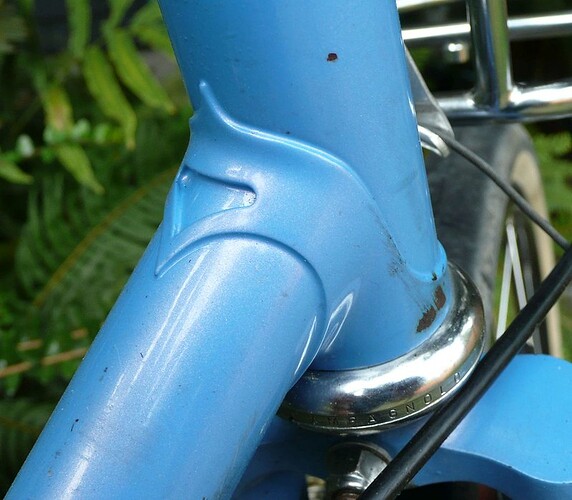
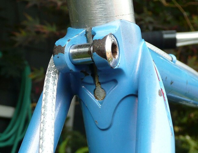
Just for fun here are a few forks I have made in the past.


2 Likes

Here are links to the notes & pictures I took from my UBI class several years ago…

https://sfcyclotouring.blogspot.com/2015/06/ubi-framebuilding-class-day-3.html
https://sfcyclotouring.blogspot.com/2015/06/ubi-framebuilding-class-day-4.html

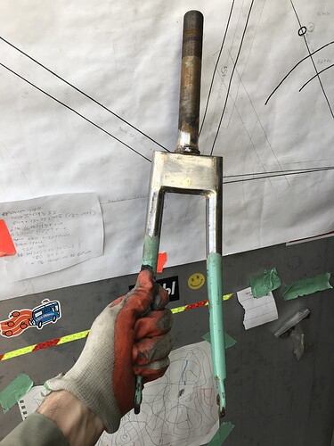
I’m no expert (I’ve built 3 forks), but I’d guess the major addition to however you’re designing & building forks currently is to measure the fork crown blade-socket depth, to account for that in the axle-to-crown stackup and determine the as-cut fork blade length:

  • Measuring Fork Crown Blade Seat
    • Check catalog specs OR use the back side of the caliper to measure the blade socket depth
    • Measure each side in case they’re different
    • Mark line across outside of fork crown
    • Measure to crown race seat

-Jim G

1 Like

It seems that you did the whole steerer/crown/blades in one shot.

2 Likes

Yep, we did everything with silver in one go. Starting with the steerer tube…by the time that’s heated up and filled with silver, you don’t need much more heat to bring the blades & sockets up to temp.

3 Likes

You need a big flame to get the crown hot enough. A rose bud is really nice. I would recommend using brass. And I do it in one go also.

1 Like

The following is not advice to a beginner/hobbyist, just a sort of memoire.

At Davidson circa late-'80s we got really fast at making steel forks, just in time for them to become obsolete! Bill made a carousel like he saw in Italy, a heavy rotating table (spun on a Volvo wheel bearing) with 4 jigs on it. Pneumatic actuators controlled by foot pedal locked/unlocked the table, and moved the rosebud torches out of the way to allow the table to rotate, then back in to heat the next fork. One guy (typically an apprentice) fluxes and assembles and rotates the table, and takes finished forks off as they come back around. The other guy is the brazer, that was usually me. Both workers have to work fast to keep up with each other, it was exhausting but actually kinda fun. We never made more than 50 forks in a session, so you didn’t have to do it all day every day. I’d have quit if that was the job!

We brazed crown steerer and blades in one go, with brass preforms inside, heated up at a heating station with two large oxy-propane rosebuds. When the fork gets to the brazer it is already at brazing temperature, so you just need to add the heat of fusion in the preforms, and watch the brass emerge everywhere around the shoreline. Destructive testing confirmed 100% penetration, pretty much no way for it to fail. And absolutely zero blobs or spatter, really nothing to clean off afterward, we didn’t even char the flux.

A bit of brass is added thru the brake holes, but the steerer also had a preform, a thin washer of brass between the cut end of the steerer and the shelf in the crown. (The crowns all had shelves, as opposed to a through-bore, so the steerer cannot poke out the bottom of the crown.) Crowns without a shelf would require some other step to prevent the crown sliding up the steerer as the parts all get longer from heat expansion. Though if you know how much movement there will be, from testing, you could just start with the steerer backed off by that amount before heating, so that it ends up in the right spot when everything expands. I think most people would rather just pin it though.

This carousel could (typically did) braze 50 forks in 50 minutes, maybe an hour max if we were slackin’. So an average of one minute to braze each one. That’s two man-minutes of labor per each, but the steel only cares how long it was hot for.

The blades are straight at this point. After the flux soak, brake hole drilled, and a quick alignment check, both blades get raked at once (requires two raking forms of course). Then the little straight part, that you always get past the bottom of the curve, are cut off roughly to length with a chop-saw, in a fixture that indexes off the brake hole. The blades get reamed and faced on the lathe in another fixture that indexes off the brake hole, real square and precise unlike the chop-saw.

Reamed and faced with a cutter just like a head tube reamer-facer, only tiny. This is to make them fit perfectly with the internal-plug-style dropouts we used. Those get brazed with preforms of course, takes like ten seconds each with two rosebuds in your hands. Since the dropouts were precisely the same length, brazed into blades that were also, the wheel always centered just right with no faffing about.

Davidson had previously used forks made by Tange in Japan, for his production models. But after the system described above was worked out, it was cheaper to make them in-house than to buy Tange forks, and the quality was higher. We also made batches of forks for a couple other brands that you have heard of. I think they get client confidentiality since they sold them as forks they’d made. I don’t snitch.

Fun times. I wonder what happened to that carousel. Cut up for scrap?
3 Likes

@hahn_rossman Thanks for that tip. I’m more comfortable with brass so it’s good to know that it’s an acceptable material for this job.

@bulgie An amazing story. Somewhere I have seen a video of a factory in Italy, in the 70s or early 80s judging from the hairstyles, where workers are making forks on a similar rotating table with pre-heating built in. I may be jumbling things up in my mind a bit here. Maybe mixing your story with something else.

In any case it’s interesting to think about adding the fork tips last, rather than raking the blades, snipping off the little straight bit, and then joining the tip to make a blade+tip subassembly. The advantage of adding the tips last would also be that it’s going to be easier for me, prone to mistakes, to adjust one or the other of them up or down a bit to get the wheel to sit straight. The disadvantage is I have no idea how I’d get the fork blades to sit where they need to be, as my jig is based on holding the fork by dropouts and steerer.

Anyway what I am getting here is lots of preheat, and brass. Those are good to know.

Is everyone building the whole thing in the fixture, or tack then finish in the open air?

@bulgie Bill still has the carousel but the whole preheating thing wasn’t set up last time I looked.
@JimN I braze in the jig. Depending on the crown you get a little wiggle room, but I think it’s easier to braze the drops in, crank them for alignment, and trim to length. Then braze the whole crown/steerer/blades at the same time. If you are building a QR fork you can file the slot to adjust the length, or slightly derake a blade if you need to.
But getting everything evenly hot should eliminate any problems.
Hahn

@hahn_rossman I was talking with Bill ( or Bob F) recently about a frame I repaired and he mentioned that you ended up with the triangle hole punch for vent holes in the seattubes? Charming to see how these things travel around or disappear.

1 Like

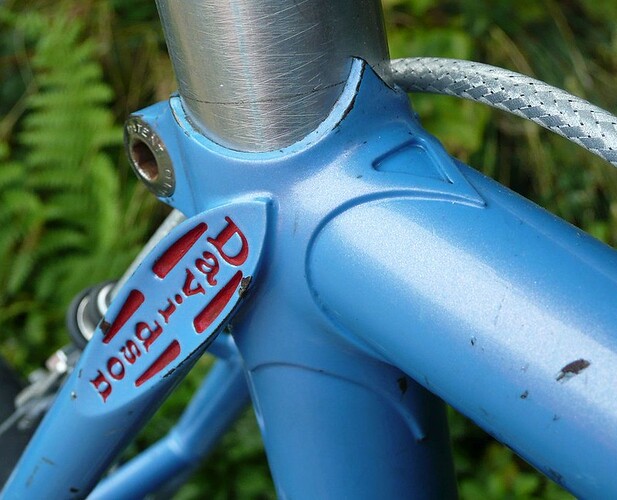
That punch was originally made for punching “windows” in lugs. There were two triangle shapes, a narrower one and a wider one. We had an inch female die, with the narrower hole, for the two TT lugs,


and a 1-1/8" female with the wider hole for DT lugs.

The wider one was also used sometimes on the back of the ST lug, below the pinchbolt ears, like so:

Then one of the FBs noticed that you could use it to punch vent holes in the ST and HT, faster than drilling. I didn’t approve of that use, since the lug-window dies were expensive and practically irreplaceable. Sure enough, one of them got a chip out of the male punch, and we couldn’t fix or replace it so we just stopped “windowing” lugs. (A good tool & die guy could fix it or replace it, but Bill sort of lost interest in lug windows I guess.) After that, it became just a faster way to make vent holes.

Hahn, do you have the whole machine? The punches were pushed through the lug via a large heavy floor-standing frame that was operated by a foot pedal. There was leverage, and sheer mass (there was a “cannon ball”, a sphere of cast iron bolted to it specifically to give it more mass), so when the punch hit the lug it was carried through by momentum. Time to punch the lug was some small fraction of a second, too fast for the human eye, so it looked instantaneous. Wham!

3 Likes