First post here. Started with steel bikes 6 years ago right as I was graduating high school. Got into carbon bikes through college while studying Mechanical Engineering at Georgia Tech. Now I work in space/composites industry full time but I still like to make bikes/bike parts in my free time.
I had to create a website and store a week ago so a local junior could use some TT extensions I made him in a UCI junior race. The store is mostly a front, but it is a great excuse to finally start working on a blog now that I am paying for the website.
I will try to post as frequently as I can, but don’t expect too much. This first post was not complete by any means so respond with questions, I will happily try to answer or spin up a new blog post on it. I still have plenty to learn when it comes to making carbon bikes but hopefully this will help someone out there get started.
Hi Iain- this was such an incredibly insightful read! Thanks so much for taking what must’ve been an extensive amount of time to document your progression. I’ve only just started dipping my toe into carbon manufacturing but my main takeaway was similar to yours at the outset- it’s totally different than welding tubes, but it’s not inherently more difficult. One of the main challenges I’ve faced is the comparatively non-existent process detail on building parts for bikes, which you’ve just solved- I’ll be digging into this blog post over and over for it to sink in.
A couple of notes and questions from my end:
I also have been using Easy Composites for most of my prepreg, mostly due to cost. Rockwest has all the same stuff I could use but at almost double the price, I can’t justify it. For what it’s worth, I was digging through images of Prova Cycles’ workshop and saw on one of their layup schedules that they’re using XC110/XC130 as well. I figured if it’s good enough for those guys making some of the highest quality builds out there, it’s good enough for me.
I’m really curious about your method for the “double C” mold method to get the laps to go into the right spots. This is also the approach Prova uses for their seat tubes but It’s been confounding me how you manage to get the sheets to line up correctly.
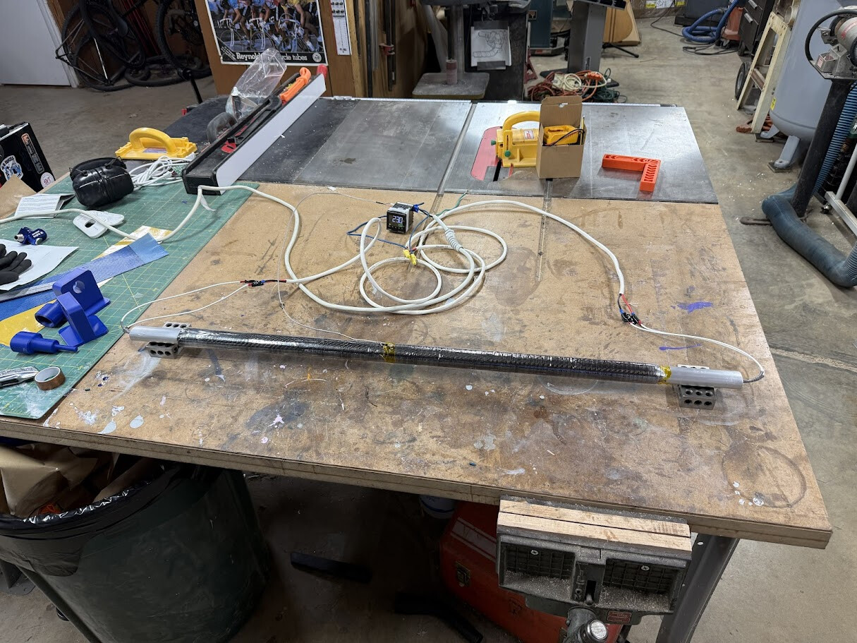
Curious if you’ve played with roll wrapping at all and how you compare it to filament winding- My current interest in carbon parts is around making my own seat tubes, and since I 3D print all my tube intersections, it seemed like a no brainer exercise in creativity to start from a non circular cross section. The male mandrel can be machined super economically, and I bored pockets in both ends so I can install cartridge heaters and do an extremely DIY “oven” curing from the inside out:
I got great consolidation of the layers with shrink tape and a foil tent “oven”. Pulling the tube off the mandrel was a bear, but doable. I’m quite happy with the technique as a starting point, but the big limitations are controlling the ID only (which means I have to test-fit clearances to my 3D print mated parts after the fact) and the inability to provide localized supports (something I really think would be powerful on a seat tube compared to a constant wall thickness).
Really love everything you’ve documented so far, you’ve made me reconsider whether filament winding might be a better strategy for my own projects- building one seems pretty straightforward but it’s obviously a big time/energy sink when I could be building more bikes! Lots to think about.
I think I know the exact image you’re talking about. Realistically, I would love to have more options with a hm fiber and maybe a toughened resin system but at the moment, fully agree that it is good enough.
I believe there are some decent easy composite videos that touch on the double c method.
The main things that I would say about it is to not worry too much about ensuring that you have the perfect matching length so you end up with exact matching steps. This will be almost impossible with a straight tube and entirely impossible with a bb. If you can get it close, it will be smooth enough on the inside and there will be good stress transfer. Especially since you may nail the spacing with it laid up, and then go to debulk or pressurize during cure and the change in bulk factor is going to mess up that perfect lap. I generally go with a 10mm offset per side per step. If I have 10 plies, I do not have 10 steps, I normally aim for +3 on my last ply(s) (and for a seatstay you might only get +2). I started with 5mm but found that I was not getting enough total overlap and if I had my plies down off a tad, it quickly turned into 3mm on the short side. One thing that I have not entirely decided how best to handle is that as you place later layers down, the diameter is effectively getting smaller so theoretically, you should be narrowing plies. I do not currently do this, mostly because preparing cut plies is already time consuming as is. This tends to result in extra bulk at the overlap area. This hasn’t caused me any issues so far, but it obviously isn’t perfect.
The big trick I have found to ensure that the long side laps end up where I want and not folded outside the part is to save the smallest ply from the recessed side and apply it to the lap side. So place the bag/bladder into the lap side, wrap the laps around the bag/bladder as much as possible, and then put the smallest ply from the recessed side on top of the bag/bladder. You will need to stretch the laps in past where they want to be to get sufficient overlap with the smallest ply for it to stay in place but that helps ensure that it stays away from the edge of the cavity. If this doesn’t make sense, I can try to dig up a pic or take one during my next layup.
I have not so I can’t comment too much. I believe filamentbikes uses it with much success. I am sure there are some others. My read on it is that you have more control over layup however you are limited to more constant shapes. I love to see someone else using 123 blocks like that. I really like the cartridge heater approach, so long as you can measure your gradient from end to center!
For removal of filament wound tubes from iml molds, I use a wax mold release instead of chemical. I think high temp rated wax will be less available but it should still exist. If you are using an expander style seat topper, the good iml control is quite nice. But yes, agreed that it is difficult since the outer surface of bikes matter so much from both a bonding and visual perspective. I do think you can count on a pretty consistent outer surface for parts with the same mold and layup. I also think that roll-wrapping lends itself to localized supports more than you think, so long as any external “butts” do not interfere with sliding 3d printed parts into place. For iml parts where I have a taper, change in diameter, or reinforcements, I wrap the part in a 1/16in thick silicone sheet stock cut to wrap around perfectly with no overlap before shrink taping. The silicone acts as a pressure intensifier that evens out the shrink tape. It could handle reinforcements at bottle bosses really well. I believe July uses a 3D printed outer wrap for some of his parts instead of my silicone sheet stock.
As for making a filament winder, I will say that the main challenge is designing a machine that can maintain optimal fiber tension. My current method is passive. I would love to change it to be done with a motor, I think an odrive+brushless dc could be a cheapish way of achieving this. Also, I have found getting spools of tow somewhat harder than prepreg, mostly because even fewer home gamers are buying a couple spools of tow than a couple meters of prepreg.
I have yet to read your article but I have it bookmarked for later. Your post timely for me, since I’m pondering a ski boot project which will require some basic composite layup.
Very cool to see there is some other lunatics out there that don’t shy away from composites! As of now I only skimmed your article, but looks like there is a lot of information in there. I’m particularly interested in the filament winder. I have a fully designed filament winder in CAD but as of now I didn’t get any further than that. Feature creep is real and it would be nice to make a super overkill machine, but I lack the experience with winding to know how to find the balance of “good enough”…
I think it really comes down to what shape tubes you want to make and how much you want to have to fuss every time it’s a new tube. I have been able to get away with a lot with just spindle, back and forth, and deposition head tilt. Getting the rollers at the end took some iterating and they’re still not perfect, but more is better. I think if I were to add extra scope, it would be an active fiber tension adjustment like Framework/Forma.
If you want to do round, oval, and slight tapers you can get away with very little. If you want to do truncated airfoils, etc, then I think it’s need to be better.
So I had some time on my hand and I think I can contribute something to the topic of printed tooling
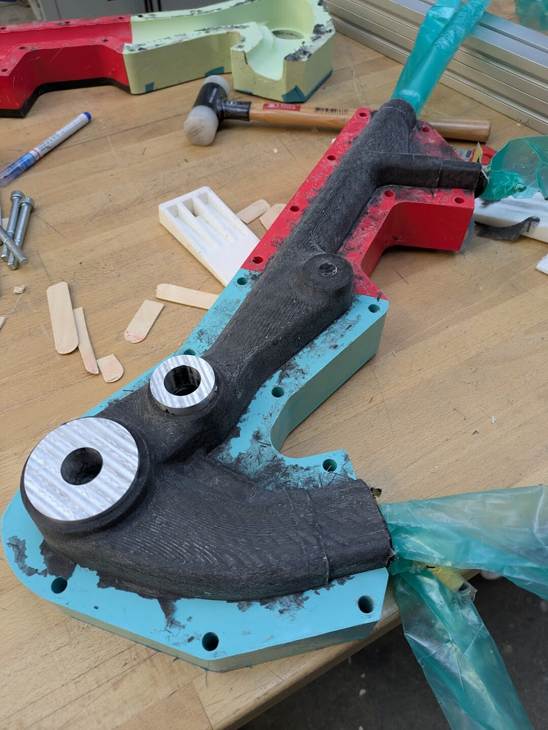
I agree that the limiting factor is the precision/tolerances achievable. With my last build I did find a little bit of a way around that by using some machined inserts that are located in the print, and most importantly are aligned with a precision ground rod. This worked out really well and there was no post machining done on the head set cups, BB and main pivot here (which is great for durability as this allows to use a fiberglass interface and avoid galvanic corrosion between carbon and metal).
I’d recommend having an M8-ish sized thread in the end of the shaft so it can be pulled out with a slide hammer. Then also the fit has to be really good so there is no slop in there, otherwise the whole thing becomes useless. This means the guided length should be as long as possible, and if the curing process is done at elevated temperatures I would make sure the CTE of the shaft and the insert is such that the fit gets tighter, or at least doesn’t get worse.
Just make sure you have plenty bag. I like the folded bags with a z-plead on the side as they open up better i feel. Just under vacuum not a big deal, but i also pressurized the bladders so it becomes more delicate and the rods don’t help there.
I’m sure this would also work with a reusable bag that has a flap that can extend around the rod und run the rest of the length of the head tube on either side if that makes any sense.
I was thinking about that for quite a while, and for this build i decided to omit any other features for this. But one of the design goals was specifically for design for manufacturing, which directly influenced the suspension layout with the vertical shock. This allowed me to have all the complexity from the suspension that is concentrated in a single print, so tolerances wouldn’t stack up. Things can still be twisted and skewed but it’s at least a little step in the right direction…