Hello everyone,
I’m currently in the process of designing a single pivot full suspension bike. Being that it’s a BB pivot, it creates some unique issues. On traditional bb pivot bikes, I would imagine that one would weld the entire frame and finish by machining the bearing surfaces and threads. This wouldn’t be impossible for me, but I would like to design around this problem if possible.
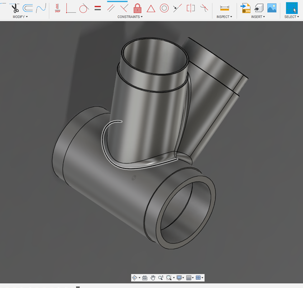
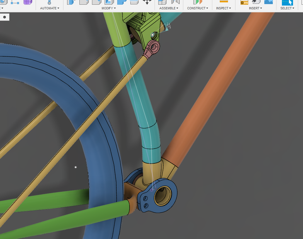
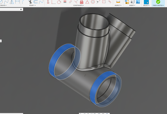
So here is my potential solution. The idea would be to print this BB tube cluster and machine the bearing surfaces and internal threads before welding. (bearing surfaces are in blue)
Potential concerns:
-Am I kidding myself thinking the bearing surfaces will stay round post weld? Even with the weld being far from the critical surfaces.
-Warping- Will it distort if printed without internal support? I’ve heard mixed bag about internal supports creating stress risers.
-Print orientation- all orientations look subpar
-Turning a thread in a printed part? Does anyone have insight in machining 3dp parts
I’ve only printed a few things in the past and this is by far the biggest. I’d appreciate any feedback.
Thanks everyone!
1 Like
Since the BB area needs to be a precision surface and threaded, I think you will end up with more problems 3D printing and cleaning up vs starting with a custom machined BB.
Is there a reason why you are not sourcing a custom bb and then 3D printing an attachment?
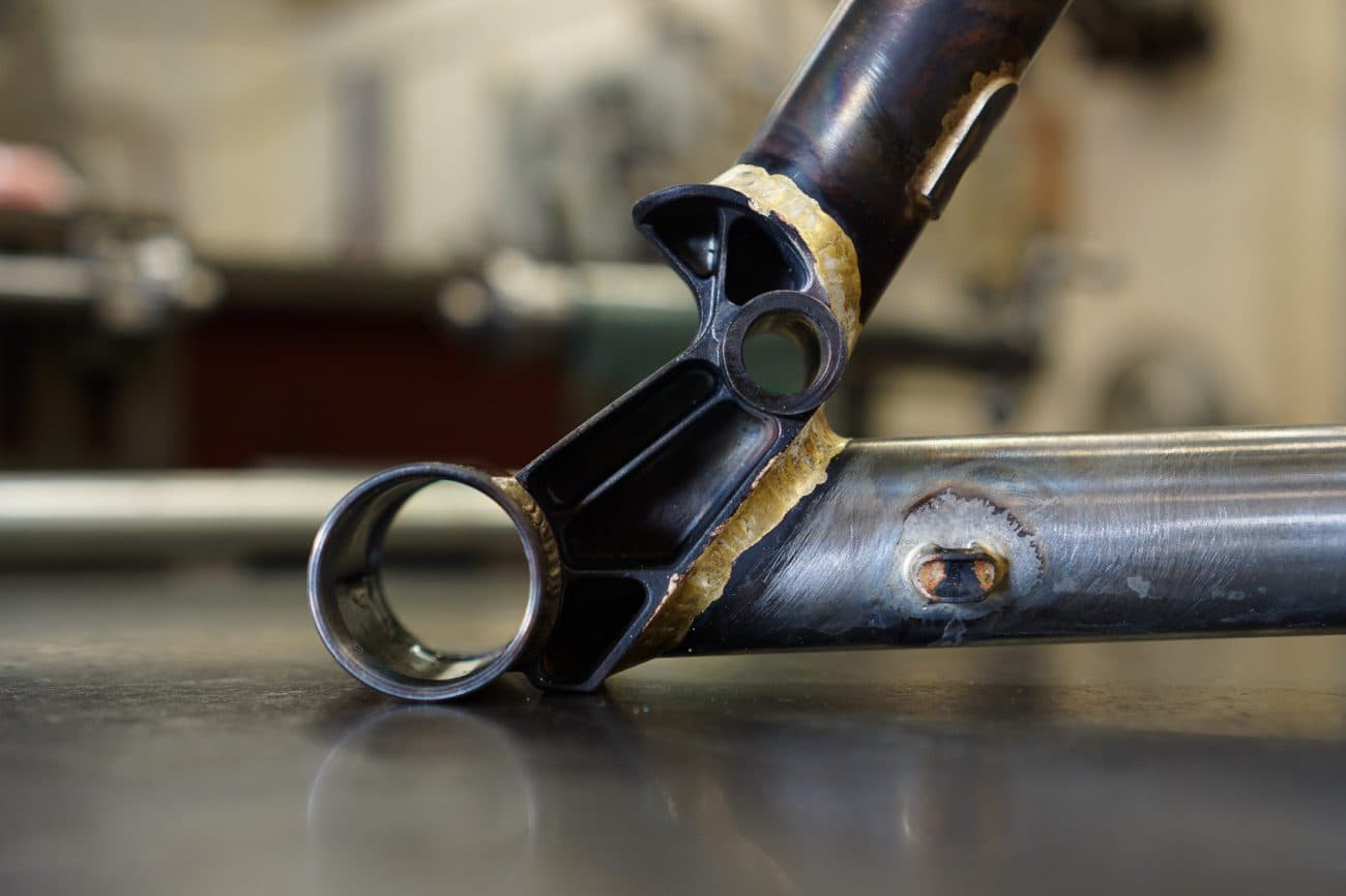
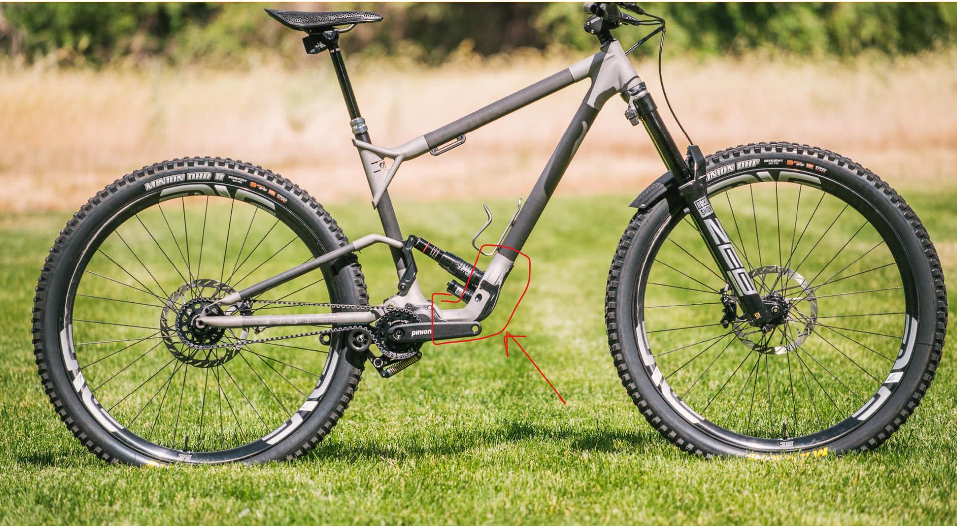
Here is an example of REEB’s pivot. I highlighted the 3D-printed pivot that is welded onto a regular BB-ST sub assembly
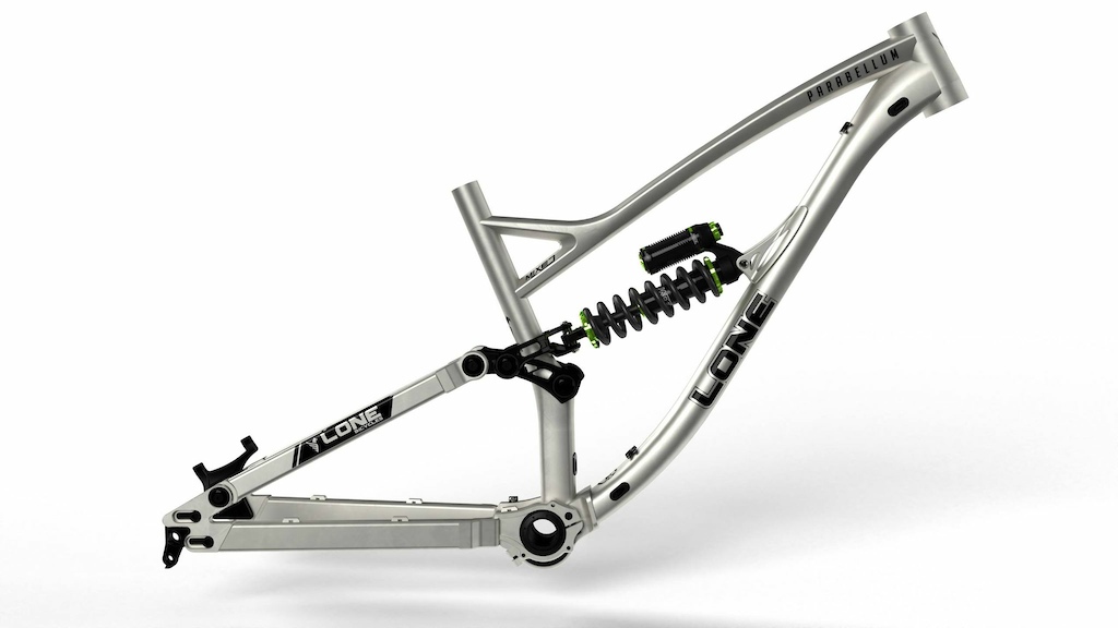
Starling uses a similar principle, but with a cast (?) bulkhead:
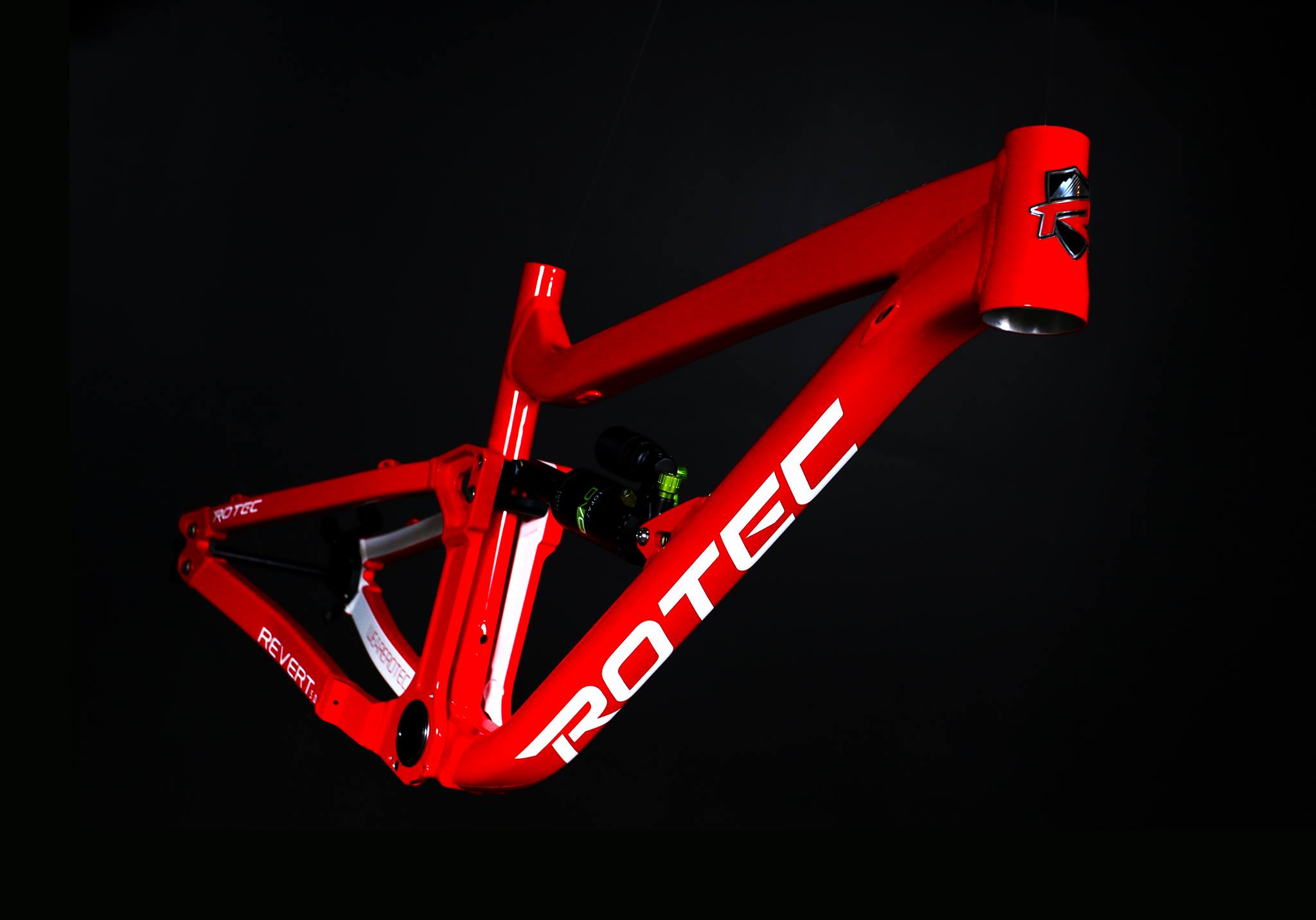
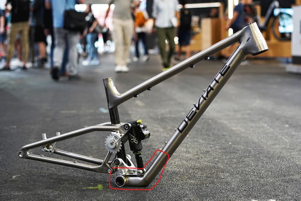
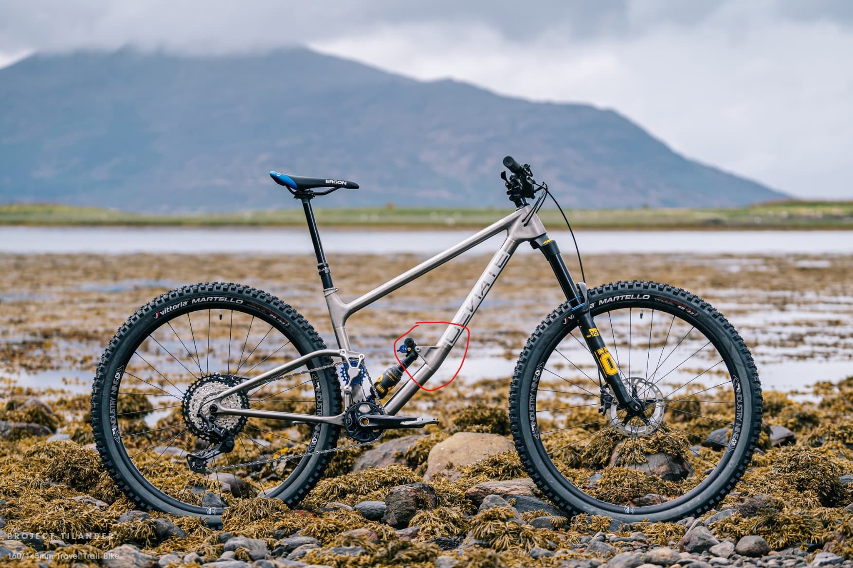
Sorry I might not have been clear with what I meant by BB pivot
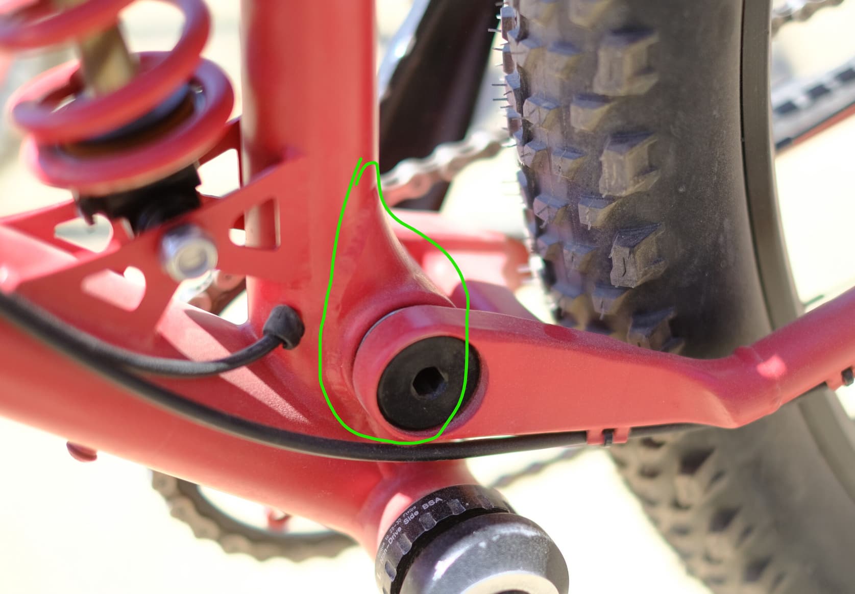
Something similar to this. Where the OD of the bottom bracket is a bearing surface.
I’m not really an expert in 3DP, but with experience in FDM printers, I would assume any critical features would need some sort of post processing based on different make and model printers having different inherent tolerances. Maybe there’s a smart way to add fixture locating features to make this painless?
What sort of fitment are you planning for the bearings on the BB surface? I always reference the Machinist Handbook for bearing fits, as the tolerances are pretty tight.
No idea about printing threads in metal, but it has never worked well for me in plastic and I always end up undersizing to whatever the tap drill diameter is.
2 Likes
I understood what you were trying to do, I was showing some examples of how I think 3D printing would be used well in full suspensions. It’s much easier to bore out small diameter bearing seats than it would be to precision machine the large OD of the bb shell.
I think your BB lug would be cheaper, more precise, and easier to make traditionally.
In contrast, I think your CS yoke and SS clevis would print well.
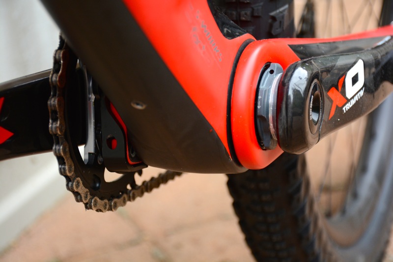
Typically people print a BB/DT lug because they need a really sharp bend to clear or position the shock to get the correct kinematic. This is not an issue because you have a TT mounted shock.
All these designs feature 3D-printed lugs at the DT to put the shock in the right spot
1 Like
Thank you both for your insights.
I had a bit of analysis paralysis. It was stuck in my head that it needed to be fully printed or machined. But I never considered making it into a sub assembly.
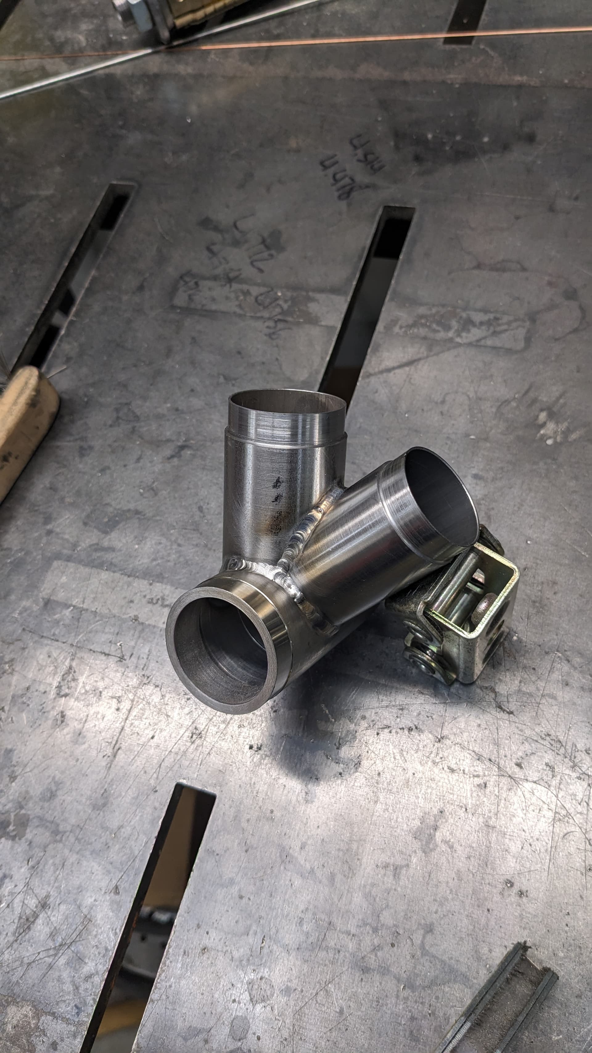
So the plan now is to make three small parts (bb shell, dt lug and st lug), weld them together. Then machine the bb threads and od bearing surfaces. Lastly weld bb lug assembly into the frame.
2 Likes
That’s what I’d do - machine the BB (simple tube with high tolerance areas), print the rest (complex shapes) and weld together.
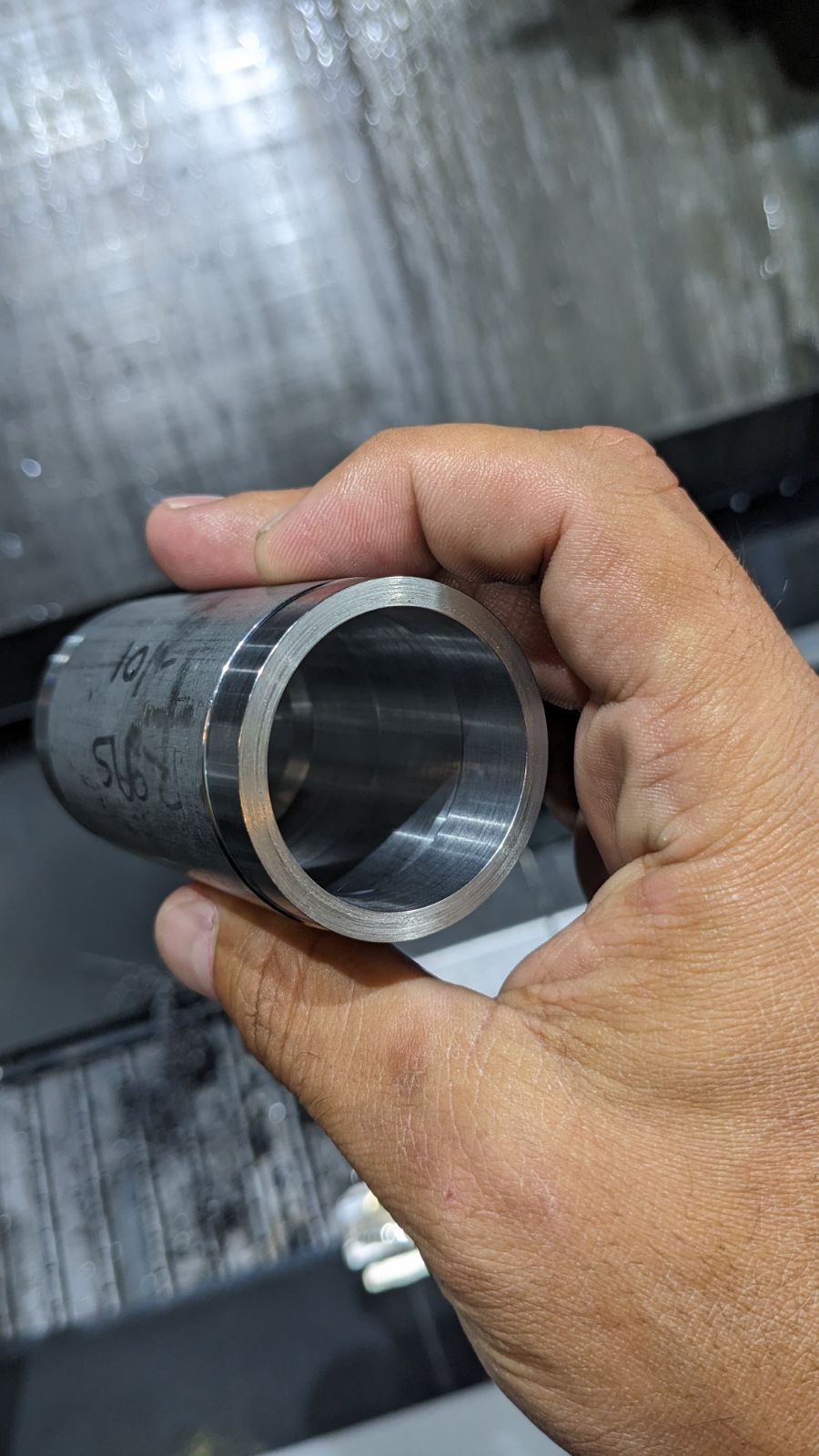
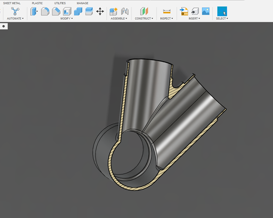
Little bit of an update.
I still need to machine the bearing surfaces and turn the ID threads
5 Likes