Hi everyone,
I’m having some challenges designing a natural, flowing UDH dropout in Fusion 360, especially when combining it with a flat-mount brake. Since it’ll be 3D printed, I’m not constrained by geometry limitations. However, using standard parametric designs made it look too rigid and geometric.
I’ve tried mixing parametric modeling with Fusion’s Form tools, but I’m still not satisfied with the result. Additionally, I want the design to be easily adjustable by changing parameters. Right now, if I modify the angle between the stays, I have to manually readjust the Form, which is time-consuming.
Does anyone have tips for designing dropouts that look more elegant and natural while maintaining parametric flexibility, or how I should go about designing dropouts?
Thanks,
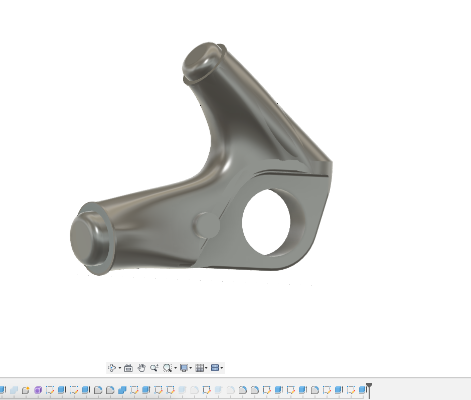
(Here is the drive-side dropout, still working on the brake side)
I think if you want this to be parametric, you’ll need to get a bit more granular with exactly what your parameters are defining. The form tools are pretty great, but don’t provide much guidance when the length starts to change, etc…
I’d be building up something like this from a master sketch that’s on the same plane as the dropout hole, and a number of lofts/sweeps. The parameters would mostly be controlling the elements in the master sketch defining lengths and angles, and then sub sketches with diameters of the elements that are on different planes from the master sketch. This would allow me to make parametrically updated derived 3d sketches that would serve as rails/guides for the various sweeps and lofts.
I think you’d then want to get a bit more formulaic, through trial and error to find what looks good, to create breakpoints when the geometry changes enough. It’s a good reason to try to create the geometry in as minimal a way as possible, so that it’s more robust through parameter changes.
Edit: Just looking at your feature list a bit more closely - you definitely want to avoid building the curvature in a part like this through the Fillet tool.
Hi Lars,
I’m not a Fusion user, but as far as I know the basics are the same in Solidworks which I use.
I’ve been making my models more and more parametric with each new project and I learn new tricks and best practices all the time.
The key takeways I have learned is that you need to try to plan your model from the ground up. Try to figure out your constraints and references early on and build on that. You don’t want to attach downstream references to geometry in the model that you may later want to change, as that may cause the model to break.
Sometimes, at least for me, it’s necessary to first build a model to get to the shape that I want. This process usually involves a whole bunch of modeling steps that can be refined away. So once I’m at the stage that I’m happy with the outcome, I completely rebuild the model with a clear view of what I have to do to get to the desired end result, but I can optimise and reduce the steps to get there.
That way I can reduce the steps in the design tree, making for a more robust model that’s also a lot easier to tweak down the line.
Sorry that I don’t have any Fusion-specific tips to give.
This is the perfect case for surface modeling!
Surfacing is a skill in itself, but it looks like you have a good eye for it with the Form tool.
Like framebuilding, the surfacing rabbit hole is deep and never ending.
The two keys I have found for making a surface model parametric and robust are:
Be careful/intentional with what references you constraint to in a model. Ie - constraining to a random surface patch or fillet edge is a recipe for a model to lose reference and ‘blow up’
Setting up clean layout sketches and geometry early in the model that will drive your parameters. I usually make a side view sketch and a top view sketch and then project the two into a 3d curve that will be my guide rails for the surface.
Lars-
I think you will have better luck using lofts to get more organic shapes while still having a robust parametric model.
You might try messing around with configurations. It makes it easy to toggle a whole batch of parameters. For example I have a stem design that has variations for steertube diameter and bar diameter. So that matrix is 2x2 or 4 options.
Hahn Rossman
I modeled a very similar BMX dropout back in 2011 (holy crap, time flies!).
Here’s how I did it back then.
I’d probably come up with a more elegant way to achieve the same if I were to re-model it from the ground up. But hopefully this screen video will give you some inspiration for how to progress your model.
Thanks a lot for this thread, it has inspired me a lot to deep dive into the dropout design on my frame
I achieve visually what i wanted to do (more or less) but i am not super convinced about my workflow
I would like to get your feedbacks and suggestions
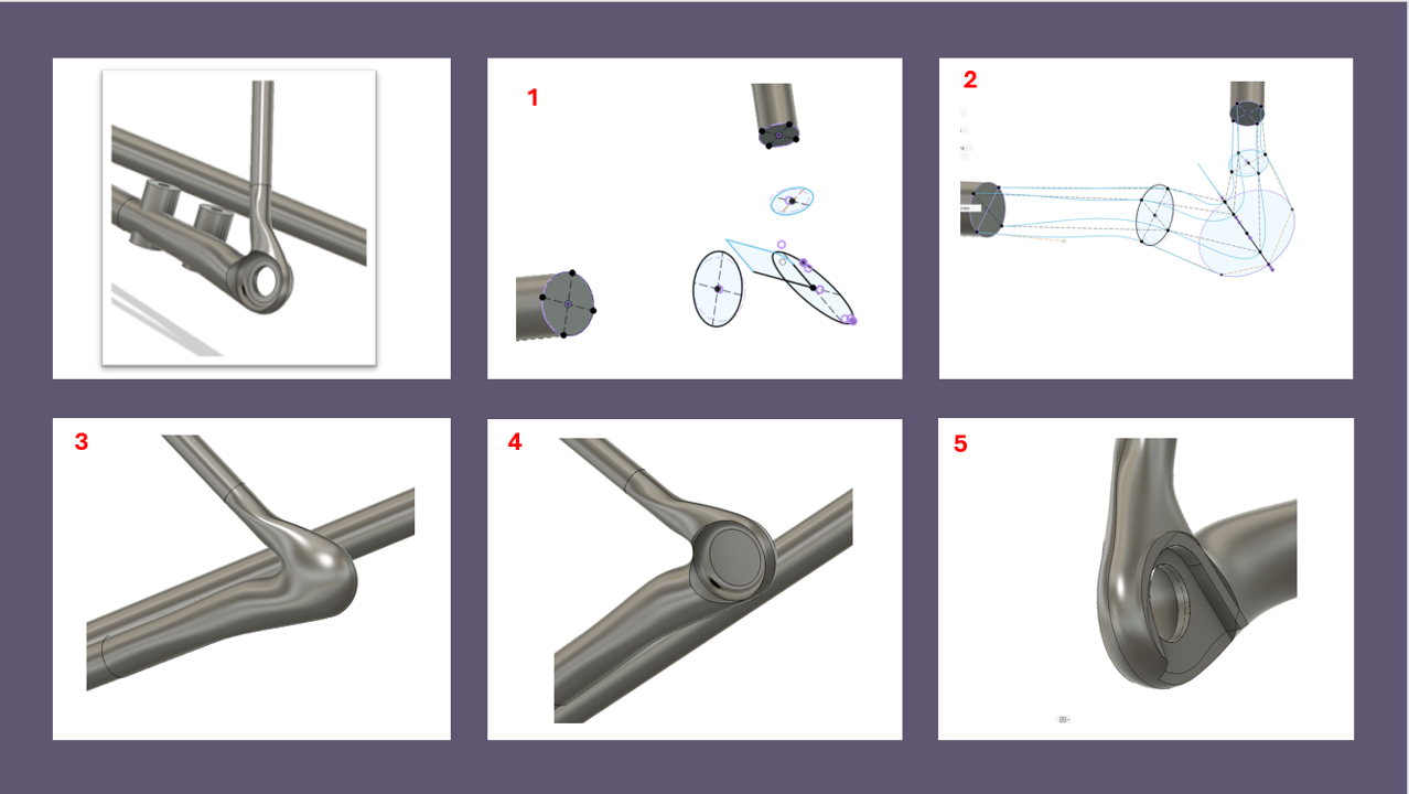
1- i first created some ellipses on different planes
2- Then i created some rails with 3d sketched planes
3- lofted
4- Revolved a profile to create the thru axle rest
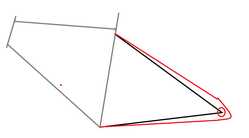
One quick tip I can give you is to not point the stays straight at the dropout axle. Give it some space below and above (like the red, sorry for the crude drawing, haha).
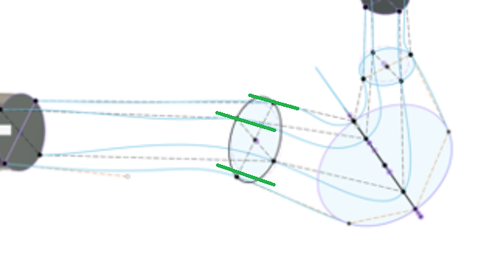
The other tip, try to avoid splines. If you have to use them try to constrain them as much as possible. Using 3D-sketch I make perpendicular lines to the circle. And every spline point has a linethat you can move around to change the shape of the spline, I make these 2 lines coincident and give the spline line a certain length. (try to draw helper lines like the green ones, and make thel line of the spline coincident to this one)
I’ve had pretty good luck creating parametric dropouts that mostly update as frame geometry is changed by creating a bunch of surfaces and using a combination of patch, loft, and sweep to create a surface body, stitch to create a solid body, and finally shell to create a hollow internal void.
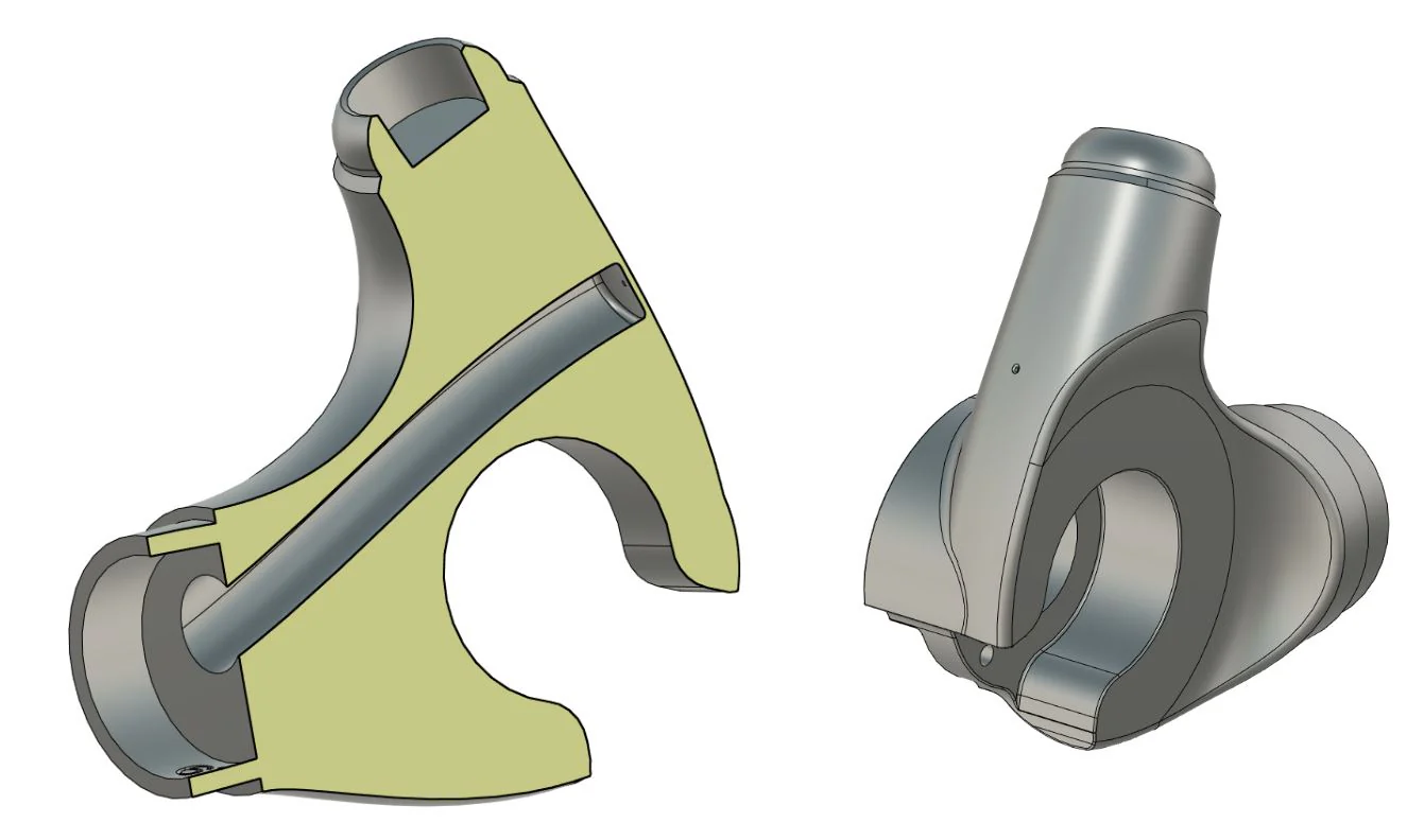
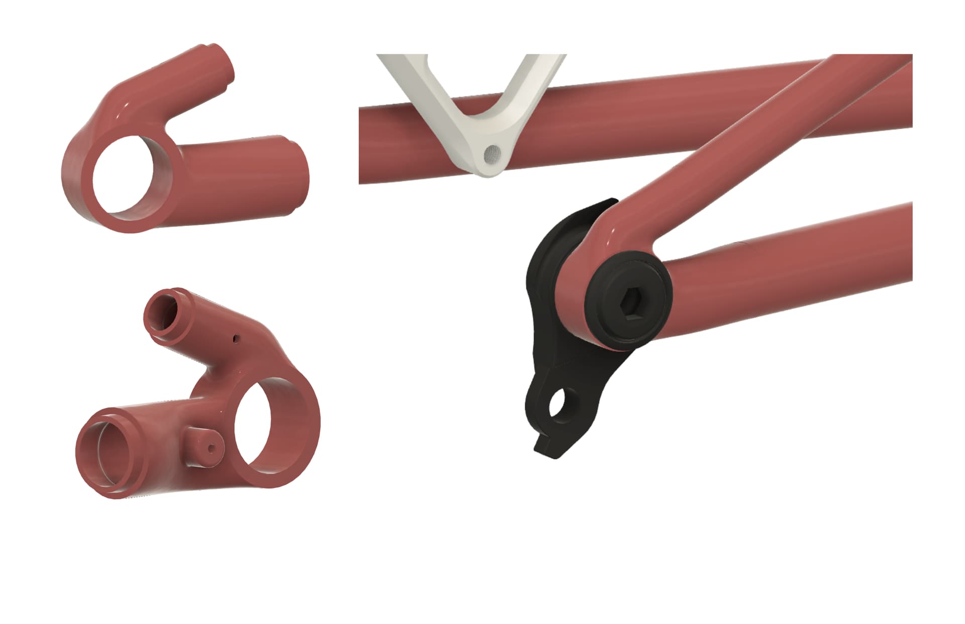
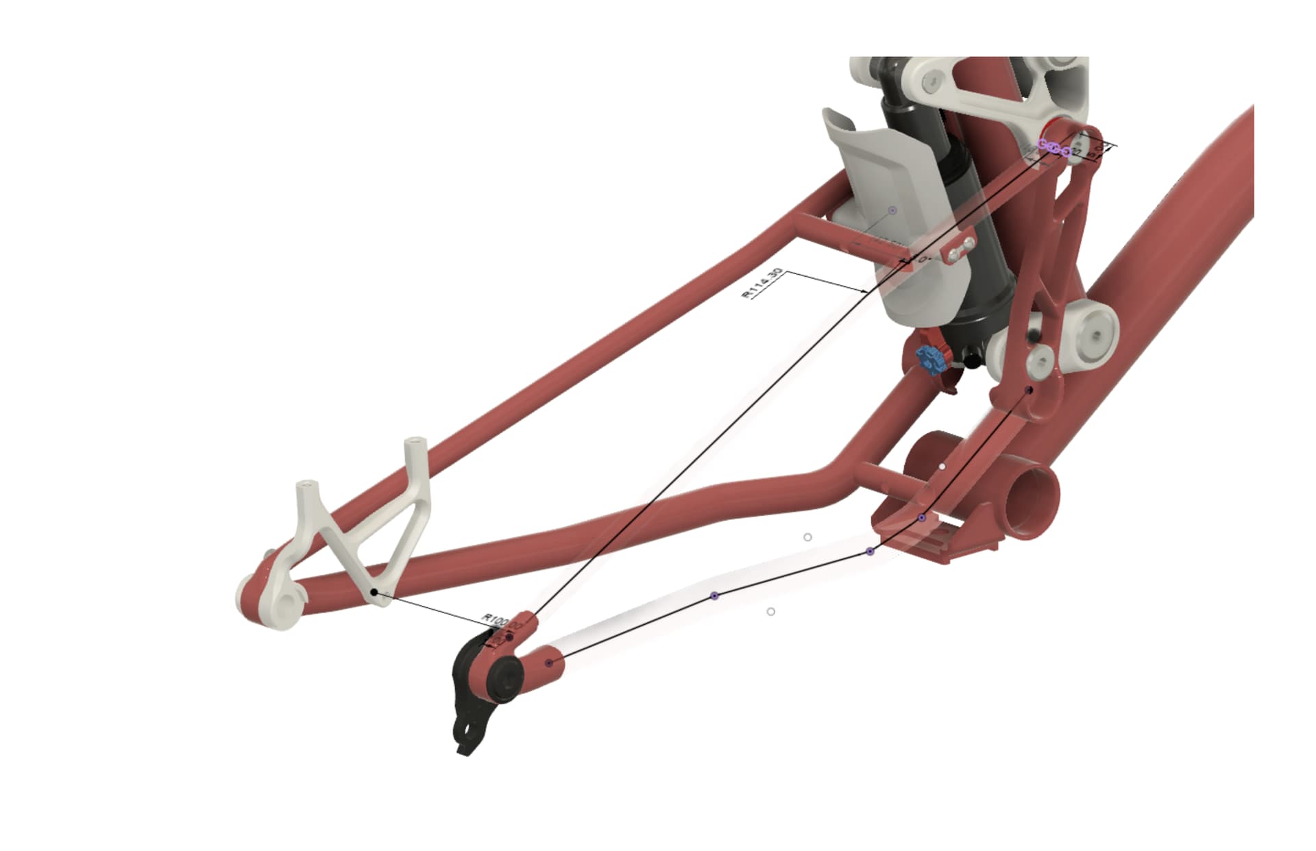
The image below shows my overall workflow for this dropout. Like Lars mentioned above, I really like drawing my chain stay and seat stay center lines tangent to the outer diameter of my dropout. I also like to keep my dropout OD relatively similar to the UDH Bolt 25-26mm OD to avoid something super chunky.
First step is creating a fully-defined 2D silhouette of the dropout and using this as a reference to create elliptical/circular/flat surfaces that I use as reference geometry when creating surfaces. I usually try to use guide surfaces rather than 3D splines or sketch lines as I can set G1 (tangent) or G2 (curvature) continuity to make sure there isn’t an obvious crease or geometric discontinuity between surfaces that should flow nicely together. I’ve found maintaining G1/G2 continuity when surfacing also helps Fusion figure out how to fillet internal edges after you’ve shelled out the dropout.
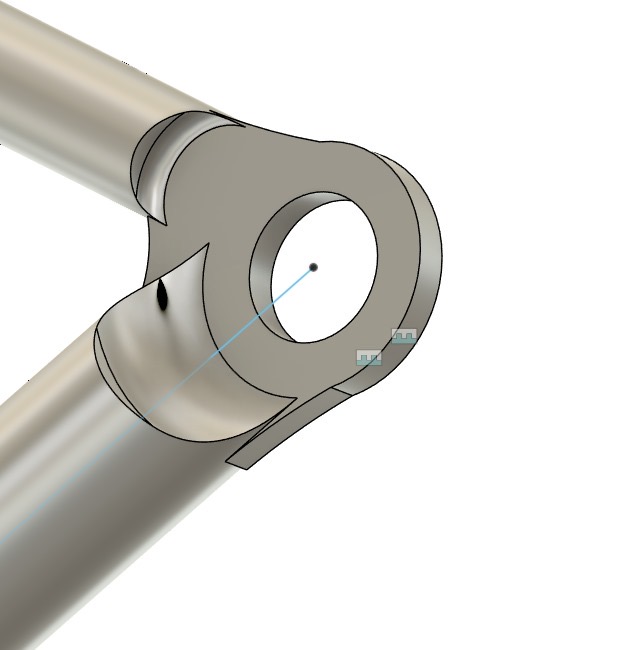
Image 3 shows the various patch surfaces I use (green, yellow, red, blue) to create the organic surfaces on the dropout. I then remove the guide surfaces and stitch together all the surfaces I want to keep. If my dropout is symmetrical, I’ll only surface one side and then mirror my geometry. I then use the loft command to connect the ends of my dropout to my seat stays and chain stays (often drawn as 2D or 3D sketches).
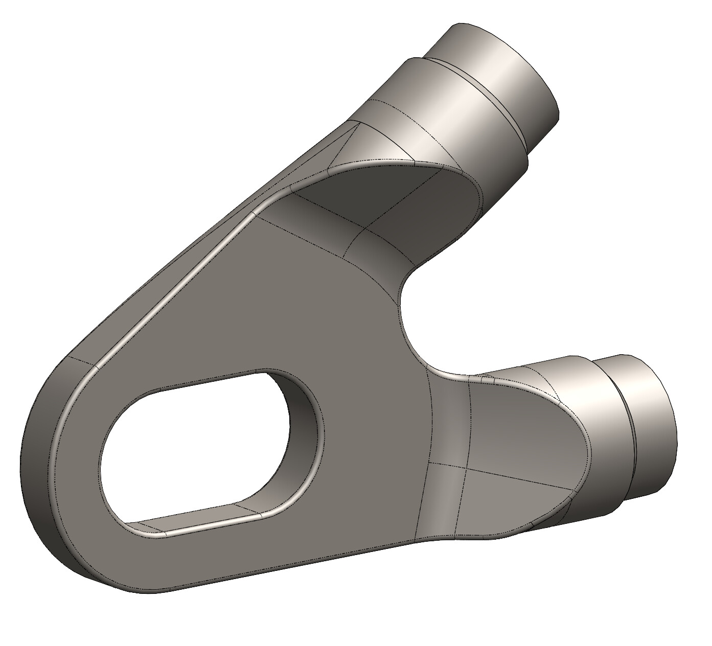
Finally, I’ll patch the very ends of my dropout and use the stitch command to create a solid body. I then use the shell command to create a hollow internal cavity and go in and fillet all internal corners (usually with chord length fillet rather than constant). This is also when I add other features like purge/vent holes, rotation stop nubs for UDH hangers, and UDH bores (I increase the wall thickness on the UDH bore section compared to the rest of the dropout body).
Here’s an example of the 2D (seat stay) and 3D (chain stay) sketches I use to connect to the dropout. I unfortunately can’t attach a .f3d since most of my models use derived/inserted components but I’ve attached a .step file. Happy to add info here too! I’ve learned so much about surface modeling from reading and watching others in the community.