My goal is to figure out the tubing dimensions for the seat post given my dropped seat stays design.
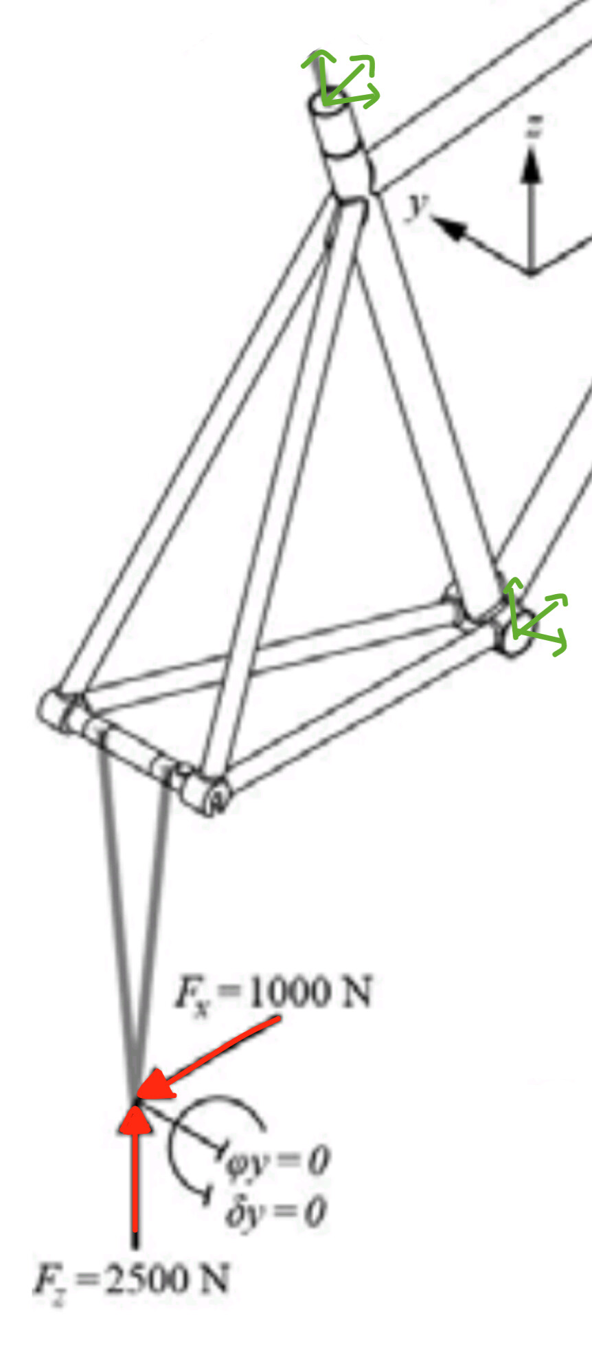
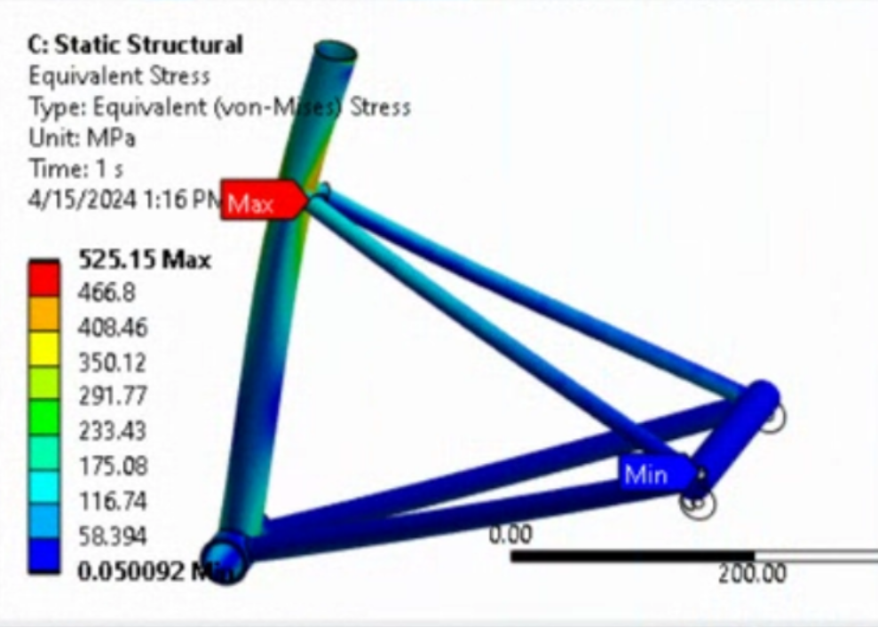
I did a finite element analysis in which I modelled the rear triangle, constraint the bottom bracket and the top of the seat tube and then applied a force of 2500N up and 1000N rearwards to an overbuilt hub that connects the dropouts. You can see the constraints (green arrows) and the forces (red arrows) applied in the image below.
I also did two beam bending hand calculations which resulted in a similar ball park stress maximum.
My conclusions:
A normal seat tube typically has the highest wall thickness at the “seat stay - seat tube - top tube” joint (around ~1.1-1.2mm for steel) I guess because the seat stays are “pushing” into the seat tube and maybe also because of the seatpost bending the seat tube.
In my case the seat stays attach to the seat tube about 160mm further down.
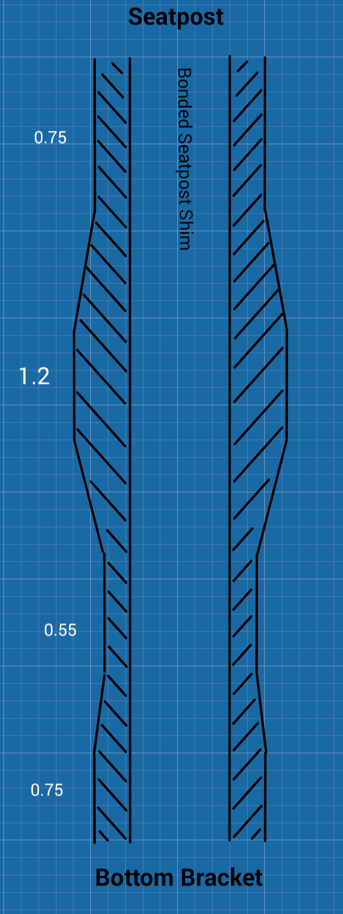
Either through custom butting or sleeves that wrap around the seat tube I can vary the thickness along the seat tube. Based on the results I came up with the following wall thicknesses assuming a high strength steel like Reynolds 853 (from top to bottom, with transitions in between in case of butting):
(A) 0.75mm at the top end of the seat tube,
(B) 1.2mm around the “seat stay - seat tube” intersection,
(C) 0.55mm between (B) and (D),
(D) 0.75mm at the bottom bracket end.
The 0.75mm at the top is rather thin but (1) I don’t have the seat stays pushing into the seat tube here and (2) I would have a very thick aluminum shim (3.75mm wall) bonded in to fit a 27.2 seatpost into a 34.9 seat tube.
I’m curious whether you would come to a similar conclusion.
Interesting analysis. According to ORA engineering, they have seen failures at the SS-ST junction, so they require a SS brace and don’t like using thin 12.7mm SS’s. So it checks out.
This tube allowed my last frame to have dropped stays that I feel good about!!
I reduced this to nearly normal ST weight by trimming the top so that the butt only extended past the SS 20mm. I still had plenty of lower butt. Memory says that seat tube ended up being 530 mm c-t. My two seconds weighing tubes shows the extra removed part of the shorted SS was a wash with the heavier tube after trimming.
I would be curious to see FEA with the seat post inserted. I have a theory that landing the seat post at the SS junction increases the chances of these failures but extending it past the SS junction removes the alleged increased compliance.
Just to confirm, the TT/ST junction would be in the 0.75mm section and the SS/ST junction would be in the 1.2mm section?
If so, I’d be a little “iffy” about having such a thin wall thickness at the TT/ST junction. There’s a bunch of heat going into an area that sees forces from a seatpost clamp, the rider weight, etc. On top of that, post-weld reaming might reduce certain sections down even further.
If you’re going to have a custom tube made, I’d rather have 2 sections that are externally butted.
If you’re going the easy route, I’d follow Daniel’s suggestions.
If you’re going the lighter-weight route, I’d get an externally butted tube, cut it to minimize the external butting and then braze (or weld) a reinforcement at the ST/SS junction. You can avoid this completely blowing up during the welding phase by just tacking it in place at the “front of the tube” and then finishing the brazing once the welding is done. (Or just braze the entire junction. I’ve done this before).
True. The question (I still have myself) is whether a bonded in (i.e. not only sliding in) shim (Dedaccai call it “sleeve”) would reinforce this area sufficiently. The shim is 3.75mm thick and made from aluminum. Together with the 0.75mm wall thickness of the seat tube the combined wall thickness would be 4.5mm. Aluminum has about 1/3 the strength of steel so let’s discount 66% of the wall thickness of the shim. Then the combined wall thickness is still 0.75+3.75/3=2mm of wall thickness that should be equivalent to a 2mm wall steel tube. This would be a totally different story if the shim wouldn’t be permanently bonded because then it could move against the seat tube and would not provide much strength benefit.
Also note that the Dedaccai “low” tube meant for dropped seat stays (link posted by Daniel above) has no shim/sleeve bonded in. The Dedaccai seat tube that is meant to have a shim bonded in has a 0.9mm wall thickness at the ST-TT intersection and a 1.6mm wall thickness aluminum shim. This is it: 31.7MM Ø ZERO UNO EXT BUTTED SEAT TUBE .9/.6/.9 X630MM + RID 27.2 SEAT POST MTV317B304 — BICYCLE FABRICATION SUPPLY
If we apply the same “aluminum discounting” like in the previous paragraph then the “steel equivalent wall thickness” is 0.9+1.6/3 = 1.4mm. This is a seat tube for traditional SS placement (near the top of the ST) which I guess just increases the stress in this area vs a dropped seat tube.
What, I guess, is important for dropped seat stays is that there is increased wall thickness (of seat tube and shim/sleeve combined?) below the insertion depth of the seat post which in my case is about 80mm below the top of the ST. My SS meet the ST about 180mm below the top of the ST.
Did you mean “…failures at the SS-ST junction…”? And that Ora recommends a brace around the ST where the SS meet the ST?
Have you evaluated a model for a conventional design where the seat stays meet the seat tube roughly in-line with the top tube? I’d be reluctant to draw conclusions based on the stress you’re seeing in the dropped stay model, but a relative comparison between the two would be useful. If you’re seeing a similar stress in each they’re probably roughly equivalent structurally. Definitely be cognizant of details that aren’t represented in your model like heat input, distortion, post-weld reaming, etc. like @ElysianBikeCo mentions. Based on failures I’ve seen online there’s sometimes not much difference between frames that last a long time and those that fail prematurely - details really matter, even small ones like cable guide placement (though that isn’t especially relevant here).
Also, purely out of curiosity, what is motivating the use of a 35mm seat tube for a (presumably) drop bar bike with a 27.2 seat post? I don’t think I’ve seen that before.
Sorry, I don’t see how a shim (installed after welding + reaming) would sufficiently reinforce that area. Yeah it might dissipate stress from the seatpost rocking back and forth, but the base material is still thin and “compromised” during initial fabrication.
You’re going deep into the engineering side of things but the solutions seem a bit like “half-steps” to overcome some fundamental flaws.
If you’re going to have a tube created for your design, why not go all-the-way? So you don’t have to glue something in? And, to echo Photon, why 34.9mm ST with a 27.2mm post? I’m just not understanding the tradeoffs, etc
I don’t mean to come off like I’m attacking you. Maybe I’m just missing something?
I’ve just read through your original post and had a look through that paper you linked…
Since FEA used to be my area of expertise I feel I can comment on both
Let me start off by congratulating you for doing a hand calc to ballpark check your fea results, that’s really good practise! Most people just rely on colorful pictures and go with whatever they show!
Having said that, this seems to be the case for paper you linked to, there are a few things in there that definitely raised an eyebrow.
The loads applied are not really explained. Why have they been chosen to be what they are? They refer to some obscure “literature”, while there are standard testing procedures in place that can very well be replicated in FEA. The article even states that there is a wide variety of loading scenarios across the literature available so the numbers chosen for this article seem quite random. The quantitative results have to be taken with a big grain of salt.
In the paper, it is stated that the model uses “solid 8-node curvilinear tetrahedral elements (element
between 0.5- 2 mm)” which is probably the least appropriate element type and size for a structure made out of thinwall tubing.
Tet elements are the least accurate in terms of representing displacement/strain and therefore stress in an FEA model, think stiffness of triangular vs. rectangular beam structures. This is particularly true for thin wall sections where two dimensions are orders of magnitude larger than the third. This behaviour can partly be mitigated by having multiple elements across thin sections. At an element size of 0.5-2mm this cannot have been the case there.
Since most high stress areas are found at or close to the connections of the tubes, it seems logical to pay particular attention to modeling these connections. There are multiple different ways to represent the behaviour of welded joints in FEA which have been industry standard for a few decades and are well researched. The article states that none of them have been used. In addition to the questionable choice of meshing, this leads to an even more unrealistic behaviour of the model.
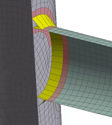
In this picture you can see an example of what would be one possible method of modeling a welded joint
So as a conclusion: The choices made for modeling the frame are poor and not explained, the load cases are random and therefor the conclusions quite irrelevant. The article is the scientific version of “I did an FEA and it was blue”
However, since the loading is not completely arbitrary and the model can be set up very quickly, it can be used as a quick way to compare design A to B in terms of “this is x% better”. But not much more than that…
/rant over
That being said, I am intrigued now to create a proper FEA model of my frame and see how much it differs… If it keeps raining like it does right now, there’s a possibility this could happen
Good you are asking. I didn’t want to make my OP longer than it already is so I simplified it a bit. Here are the details: I will probably use Titanium tubing hence the 34.9mm diameter ST. I translated the titanium wall thicknesses (1,1.6,0.75,1) to steel wall thicknesses (0.75,1.2,0.55,0.75) because more people are familiar with those and can comment. It also allowed us to reference the Dedaccai tubing for dropped seat stays. Another reason was that the FEA was done on a 0.55mm wall steel seat tube with a 34.9mm diameter because the “known good object” (see below) had these tubing dimensions and so I know that these steel tubing dimensions work. But I wasn’t sure about the wall thickness at the top of the seat tube and how much strength the bonded in shim would add…
Why would two tubes with the small tube bonded into the big tube (OD of the small tube being equal to the ID of the big tube…) be significantly weaker than one tube whose wall thickness is equal to the combined wall thickness of the two bonded tubes (assuming the bonding holds up which it should because it has a lot of surface area)? It does sound a bit sketchy but I can’t come up with a theory why those two (the one tube vs the two bonded together tubes) wouldn’t be roughly equal.
The fact that the Dedaccai ST that is designed to be used with a bonded in shim (31.7MM Ø ZERO UNO EXT BUTTED SEAT TUBE .9/.6/.9 X630MM + RID 27.2 SEAT POST MTV317B304 — BICYCLE FABRICATION SUPPLY) has only a 0.9mm wall while the Dedaccai ST that is designed without a bonded in shim (29.6/28.6MM Ø ZERO UNO EXT BUTTED LOW GEO SEAT TUBE 1.2./.6/.8 X 620MM 27.2 SEAT POST MTV286B311 — BICYCLE FABRICATION SUPPLY) has a 1.2mm wall means that the bonded in shim does something. The Dedaccai shim is only 1.6mm thick and reduces the wall thickness from 1.2mm to 0.9mm. My shim would be 3.75mm thick…
Don’t hold back. I hope there are some ideas that change my perspective. Hit me hard
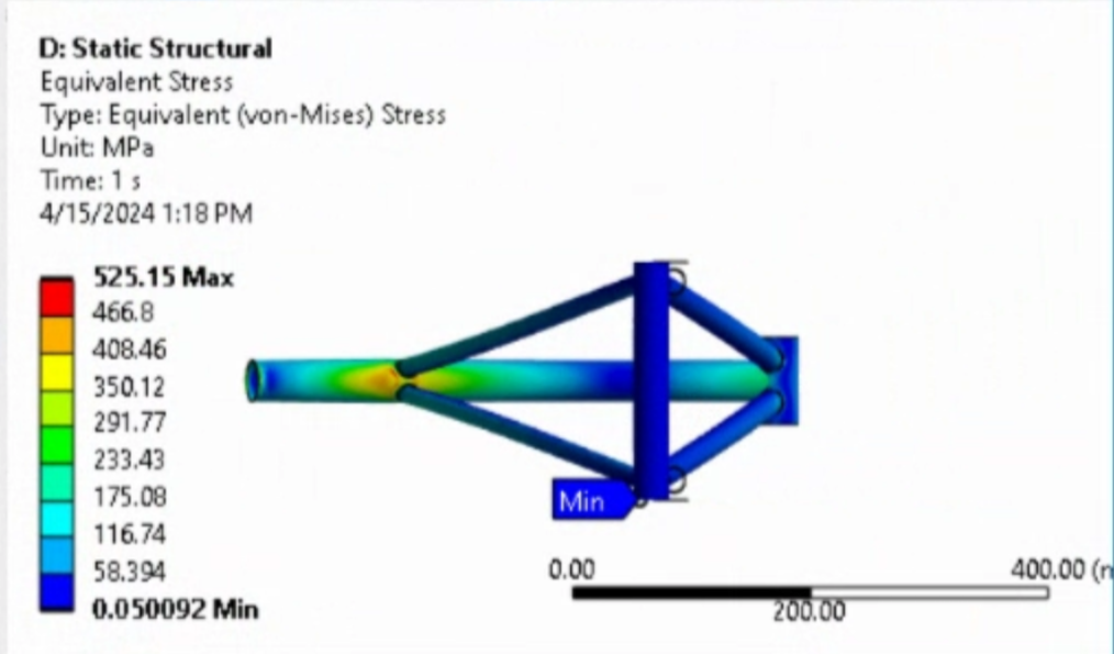
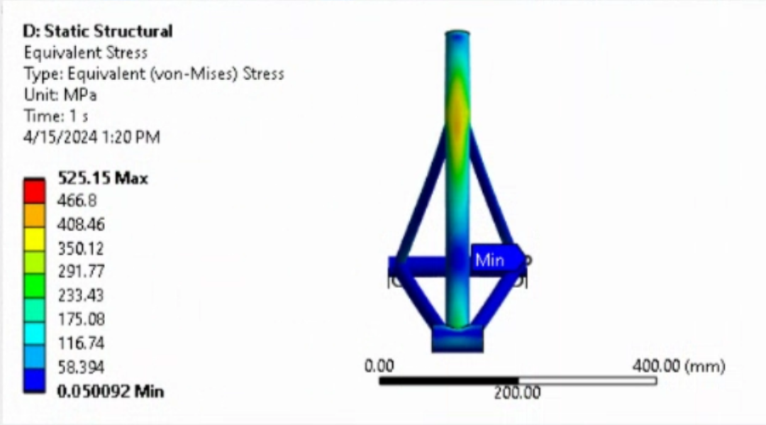
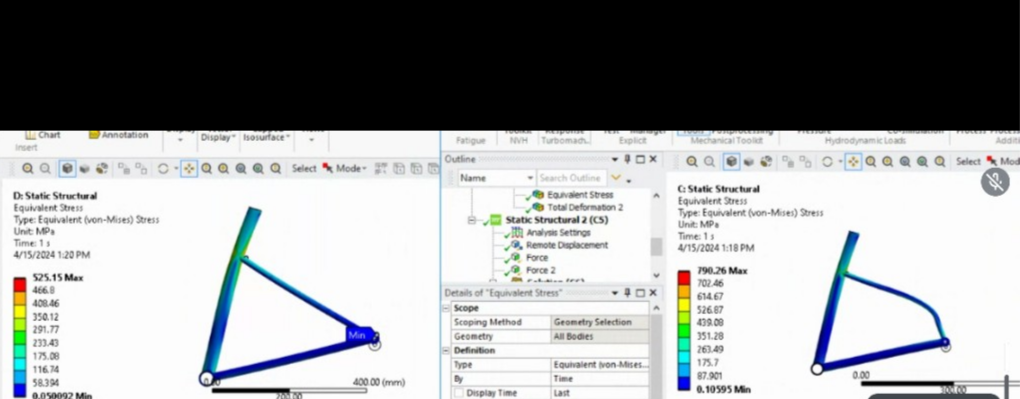
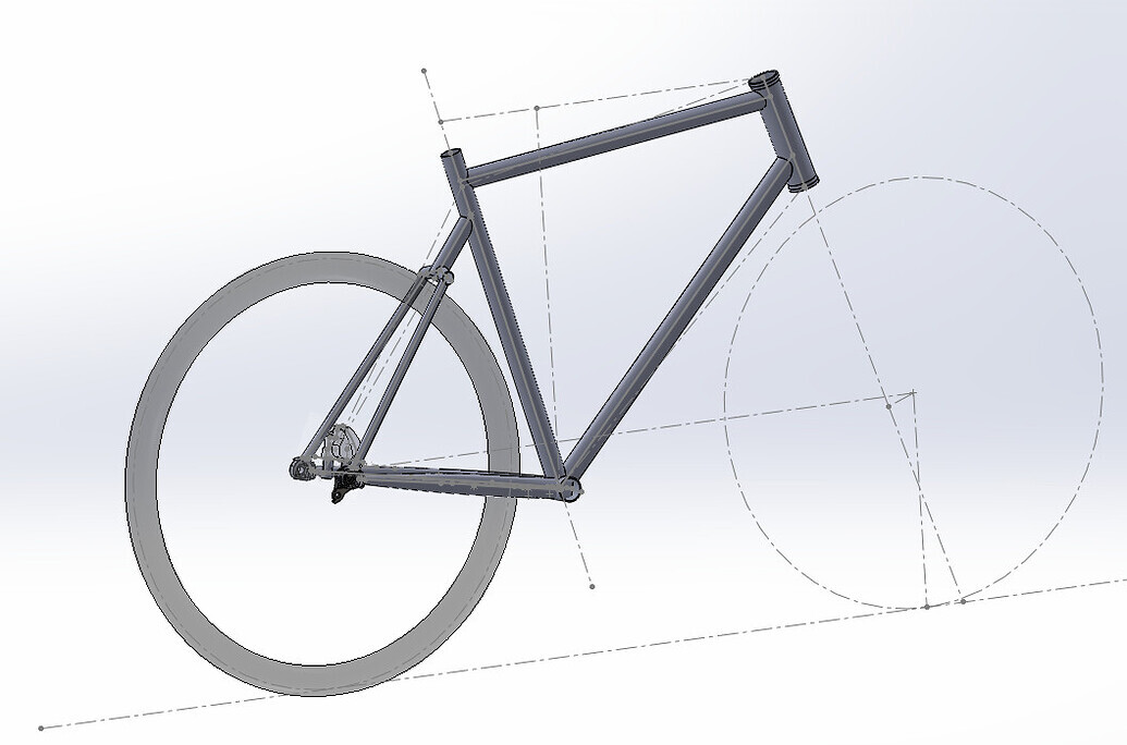
Some context: The FEA was done as a comparative study in which I tested my dropped SS design against a dropped SS design which I know works and whose geometry and tubing dimensions I had, see the picture below with my design on the left and the “known good design” on the right. This “known good design” is being sold and ridden for many years and there were some iterations… The goal of this study was to see whether the stresses in the seat tube would be greater in my design than in the “known good design”. I didn’t pay particular attention to the magnitude of the stresses the FEA spit out. My other conclusion was the relative distribution of the stress along the length of the seat tube. This confirmed the need for a higher wall thickness (or a brace) at and around the SS-ST intersection. The “known good design” has a brace at the SS-ST intersection although I didn’t model this brace in the FEA. From there I asked myself what the wall thicknesses should be for the rest of the seat tube (or where braces would need to be added).
On the arbitrariness of the loading: True. But the magnitude of the load doesn’t really matter for the A B comparison and, for this very simply A B comparison, I didn’t want to simulate a weight on the seatpost but I thought about doing that going forward. What loading setup would you have done?
How does your frame look like? Does it have dropped seat stays?
So that’s cool then, just as I said! These quick’n’dirty FEA models are great for an A/B comparison since they are quite easy to whip up! I was just a bit surprised to see this in a published scientific article…
Just as I said, for the purpose you explained, I’d have done the exact same thing probably. Maybe modeled with surface quad elements since it speeds up computation time significantly and the influence of the actual meshing on the stiffness and therefore the stress distribution is less pronounced but it probably works the way you did as well.
That being said, the difference in displacement shape of the SS members between the two versions looks interesting, I’d investigate where that comes from!
That’s my frame… it does have dropped stays but they are also segmented. So I would do a comparison of modeling techniques using my design. The geometry is too different to compare results.
Since Photon asked if I had any experience with seat stays welded to seat tube even with the top tube I can add a little of what I have seen.
This will only apply to Ti but I am sure can be translated to steel with adjustments to wall and diameter. In the early 90’s before I arrived at Moots, the YBB soft tail was welded with a 1-1/4" x 0.035" seat tube with a Ti sleeve pushed in after welding and welded around the top and in the slot to take it down to 27.2. Really bad idea but this is what I got to fix as most all of them broke at the top tube weld in front of the seat tube from the YBB banging into the back of the seat tube. Without going into details we would replace the top of the seat tube with a typical seat tube insert pressed and welded into the top of the seat tube with a new YBB monostay welded on the back. For many years we never had any problems with a Ti pressed in and welded insert that takes it down to the 27.2 I.D.
When we switched to a 35mm/1-3/8" diameter seat tube we were able to use a 0.032" wall tube, approximately the same weight as a 1-1/4" x 0.035" tube, with a seat tube insert that has a 30.9 I.D. Then we glued in an Al insert to take it down to 27.2 I.D. IMO this works well, strength and the comfort of the 27.2 Ti post while eliminating the challenges of reaming and honing the Ti insert for a smooth fit.
In my experience with top tube seat stay junctions that are not directly opposed to one another, you battle seat tube bowing from welding on one side of the thin-walled tube. Again this is in Ti. When we needed to lower the monostay on the back of the seat tube relative to the top tube we always had some of the weld hit the insert for extra insurance.
Not a dumb question at all. It is a touring bike and the seat stays play an important role in how I attach the pannier bags. This isn’t relevant to this structual topic (wall thickness of the seat tube etc). So I didn’t mention it. But I will introduce the idea in a separate post when the bike and the panniers bags are made (and it works).
I wouldn’t do dropped seat stays otherwise. The small comfort gain wouldn’t be worth the extra weight to me personally.
That is really interesting. But I didn’t fully understand what the difference is between the old solution (from the early 90s that caused problems) and the new/good solution. I understood that in both cases you had the same OD, the same ST wall thickness and an sleeve/insert/shim.
Do you remember what wall thickness of these 27.2 seatposts were? I did some cantilever beam bending calculations and concluded that for my 73kg weight (161 lbs) a 0.9mm (0.035") wall would be sufficient.
The problematic design had the 1-1/4" x 0.035" full length with an ~ 3.5" long tube slip fit into the top 3.5" of the seat tube. Then they welded the rim and the slot. This insert really didn’t give the tube any strength to the joint that failed.
The common design solution, and the one I have always been involved, with used an 1-1/4" x 0.095" (bored to 27.2) with one end ~1.00" turned to an O.D. to create a press fit into the top end of the seat tube and welded at the seam. We turned this piece to 3 different diameters to have the beginning slip, the middle snug, and the last third interference fit.
For the seat post material we worked with Sandvik to have them hold a very tight tolerance on the O.D. on 3/2.5 CWSR 105 with the dimension of 1.070" x 0.040" plus 0.000" minus 0.004" in O.D. At the time they claimed this to be their tightest tolerance material for O.D. they made. This material provided excellent strength and ride characteristics.
Over the years I worked with Sandvik to find ways to maintain the weldability and mechanical properties of tensile, yield and elongation that aerospace called out while saving a couple steps that aerospace called out that the engineers at Sandvik told me had no negative effect on these properties. ie a 0.0001" internal etching aerospace called out.
I think the “varied outer diameter insert” to create a press fit (at the top) is a great idea.
I thought about glueing this insert into the seat tube because this reduces the gap between the insert and the seat tube further. The advantage of this would be more stiffness (similar to the effect the press fit has). A potential disadvantage of using glue would be a more sudden stiffness drop right below the bottom end of the insert. The reason for this is: Without the glue you have an incrementally growing gap between the insert and the seat tube as you go down. With the glue (if the glue works as intended and fills the complete gap between the insert and the seat tube) there is zero gap between insert and seat tube along the full length of the insert. And then below the insert you have a sudden drop of “combined wall thickness of insert+seat tube”.
Here is an illustration showing the bonded insert on the left and the non-bonded insert on the right:
On the bonding vs no bonding question I decided for no bonding mainly because that decreases the chance for a local stress concentration below the bottom end of the insert/shim. I think that is also what @butchb did.
I see three ways to make the shim:
(1) gradual wall thickness change.
Independent of manufacturability what do you think is best?
My favorite is (2) because the gradual wall thickness increase from the bottom probably is best to avoid stress concentrations and you have a longer press fit section at the top than with option (1).
And the top of the shim also needs the slit/cut like the seat tube, right? Otherwise it couldn’t be clamped by the seat clamp…