Hey everyone!
Heads up, this turned into a much longer post. This is my personal understanding of bike suspension kinematics and how I apply that understanding to designing a full suspension frame. Ask questions, let’s all level up!
Background
The biggest reason for me getting into framebuilding is riding bikes the way I want to ride bikes. For the last several years, that goal bike has been full suspension and made out of steel. Since leaving big S in November, I’ve had loads of time to focus on this project and it’s finally at a point where the bike is becoming a reality. So I thought I’d present a suspension deep dive and share with y’all how I designed my bike!
Living on the Front Range in Colorado, we have a very specific type of mountain bike trail. You pedal up something mellow for 30-50 minutes, then you turn around and descend for 5-15 minutes on rocky, hardpack trails mostly made of decomposed granite. I’ve always seen a smaller travel bike with good pedaling character and fun downhill capabilities as the ideal bike for these trails.
The Dirt Church
I’m calling this bike the ‘Dirt Church’ - it’s the bike I plan to grab on Sunday mornings when the trails are empty and there’s plenty of time for adventure. What started as a 130F/130R 29er has evolved into a 150F/138-150R MX.

Designing the Bike
Skeleton:
Every bike starts with a Skeleton file. This is a master component that holds all of my driving sketches. I start with the geometry for the bike at top-out (TO).
For the sake of argument, I feel that any suspended bike should be designed around the sag point, since that is where the rider will be the vast majority of the time. In the kinematics section, all nominal conclusions are based around the sag point.
However, since most published geometries online are at TO, I also start my model there to stay grounded and make easier comparisons.
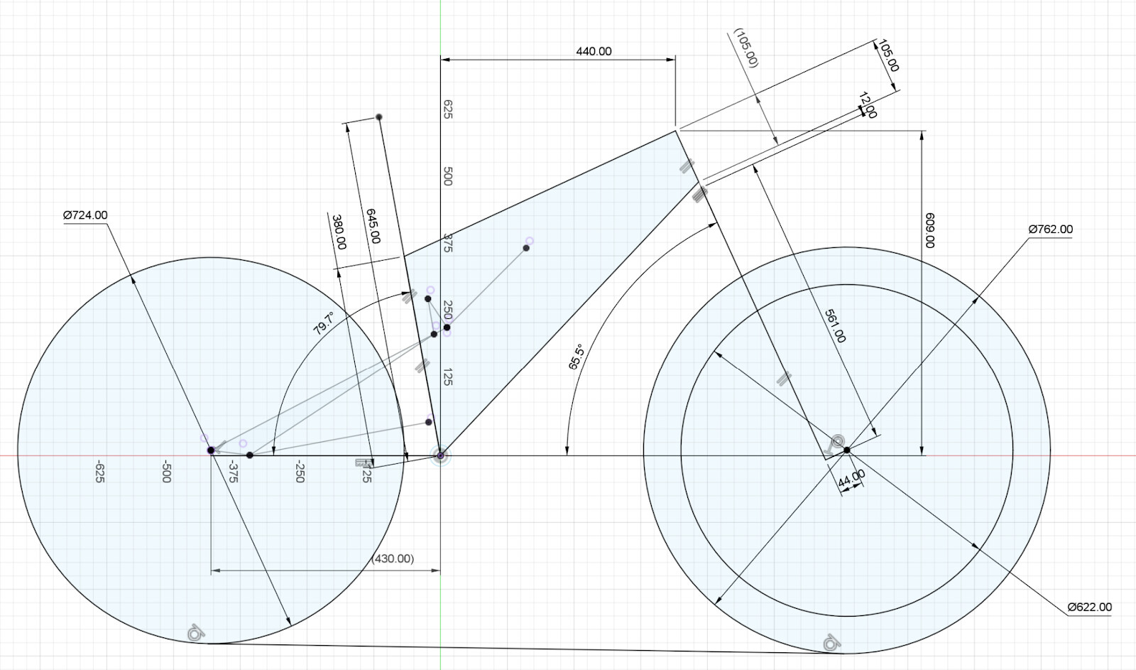
Figure 1: Dirt Church top out geometry and wheel sizes
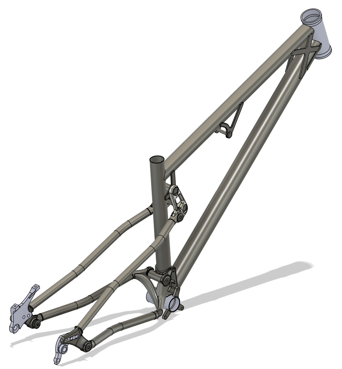
Phantom Model:
With the skeleton sketch in place, I start placing components that I know I’ll need clearance to, or have their own specifications.
These are things like water bottles, the fork crown, derailleurs/chains, brakes, tires etc.
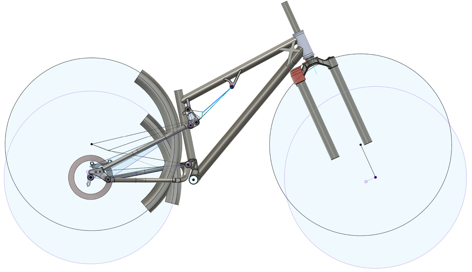
Figure 2: Side view 3D clearance check for tires and fork. Top-out and Bottom-out shown
Note: I bake in a +10mm clearance on MTB tire models.
Kinematics:
In bike design, everything is a compromise. There is no ideal shape that fits every person in every instance. Full suspension design only amplifies this fact. But if we go into the process with a picture of the ideal use case, we can make a bike that is awesome for its intent.
The current design is version 6 of the kinematics. Pivot placement is always an iterative process bouncing between Linkage and CAD. There are loads of downsides to the Linkage software, but it helps me visualize how a kinematic change affects the real world dimensions of a bike.
-
E.g.: changing anti-squat by X% means the main pivot moves up/down Y mm.
-
Pro tip: Once there’s a roughed out Phantom model, put a screenshot into Linkage so you can avoid putting a pivot point in the middle of your water bottle. Ask me how I know -.-
Layout:
When I started out, I picked a single pivot design due to the simplicity of only worrying about one pivot point. Single pivot designs are sleeper powerful in this era of single ring drivetrains because the achievable anti-squat value can be very favorable and changes minimally throughout travel. But, the more I played with this layout, the more I found limitations with a water bottle location while also maintaining the leverage rate + travel number I was aiming for.
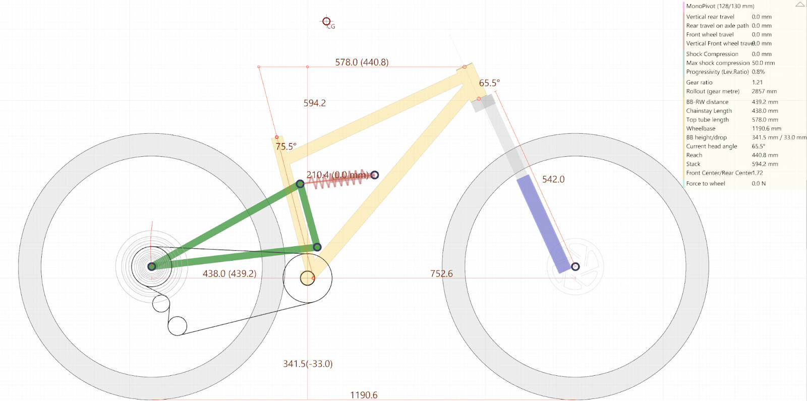
Figure 3: Kinematic iteration 1 - Single pivot
I solved this by putting the front shock mount on the top tube and introducing a linkage. This opened up space for a traditional down tube water bottle! But now there was an issue with how the bike behaves under braking, anti-rise.
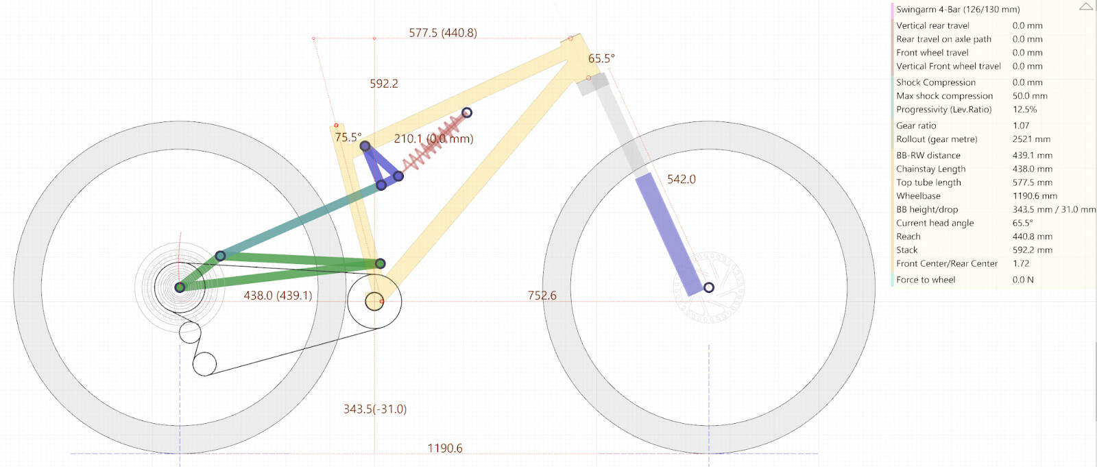
Figure 4: Kinematic iteration 2&3 - Linkage driven single pivot, top tube shock mounting
I re-modeled the layout as a flex pivot in the seat stay - planning to undersize the SS tubing to introduce a slight deflection, but enough to tune the anti-rise. This layout lasted the second longest, but was ultimately scrapped when it was time for FEA. Due to needing to model the seat stay in its ‘relaxed’ state, the SS/Linkage pivot were not concentric in 3D and I found this too great of a challenge for FEA. Maybe there’s a way, maybe I’ll pick this back up again ![]()
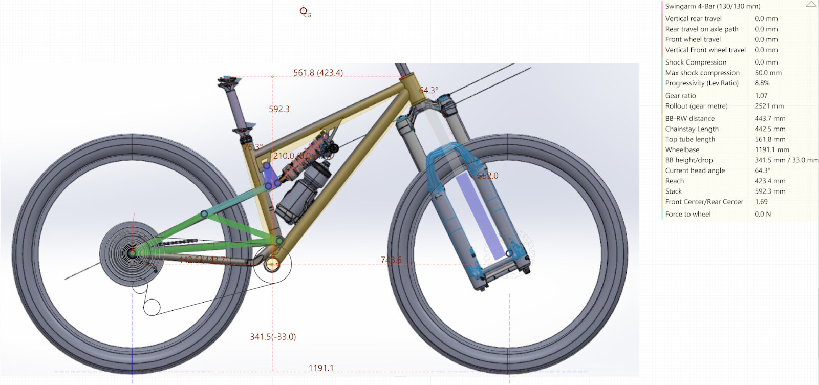
Figure 5: Kinematic iteration 4 - flex seat stay
Second issue came from the manufacturing side. All the layouts so far would require a solid rear triangle. Plenty of people use this method, but I saw a space issue coming in my tiny shop for a frame jig, front triangle jig, and full rear triangle jig.
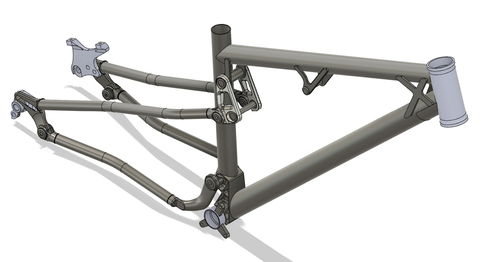
Ultimately, this led me to the good ol’ four bar Horst layout. The appeal for this layout is the increased fine tuning of the anti-rise character while also solving some self-imposed manufacturing limitations. The added bonus is the modularity of the layout. If I want to play with chainstay length, I would only need to fabricate a new seat stay. Braking response bad? Tweak the dropout pivot slightly. Don’t like the leverage rate? Move the front shock mount. (mostly, this one gets more involved in a hurry)
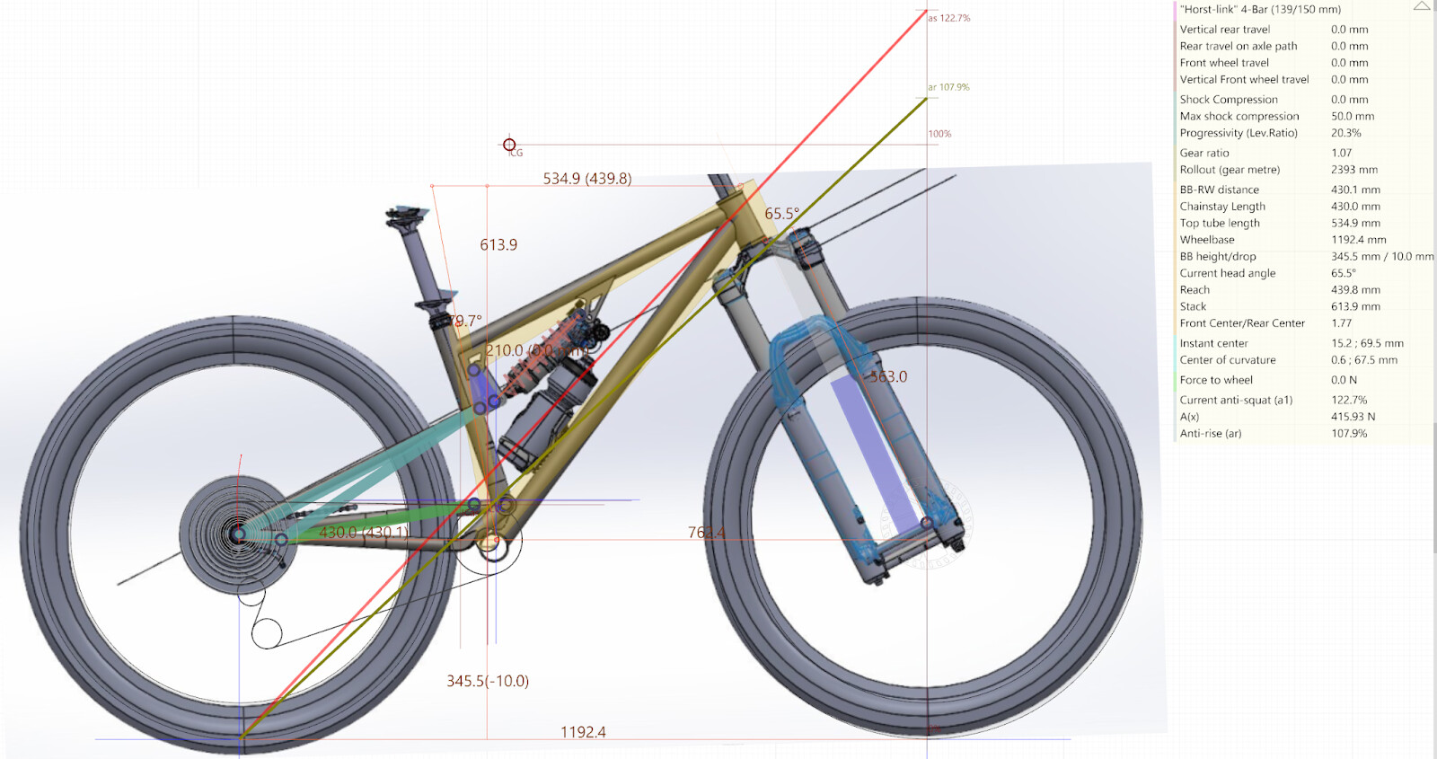
Figure 6: Kinematic iteration 5&6 - horst pivot
Center of Gravity (CoG) - where’s the human?
IMO the most important aspect of full suspension design is determining where the center of gravity for the system is located. A great community deep dive is here Chainstay Length Discussion
Drawing a horizontal line through the Center of Gravity and intersecting it with a vertical line drawn from the front tire’s contact patch gives the ‘100%’ reference location for anti-squat and anti-rise values later on.
What this also means is that two riders with significantly different centers of gravity on the exact same bike will experience the kinematic behavior of that bike very differently.
- E.g.: a taller rider with higher CoG will have a lower %anti-squat than a shorter rider with a lower CoG.
Most larger scale companies will choose the same number and apply that to all sizes of bikes. I have seen ranges in value from 800mm by the Athertons down to 615mm from Neko’s Frameworks bikes.
- The CoG values for my small size is X:40, Y:685
A large design goal for my project is creating a platform for custom sized kinematics. By using a few 3DP parts I can push and pull the design around to meet specific needs.
Anti-squat:
Anti-squat is the opposing force of the chain during pedaling to counteract a rearward weight shift of the rider during acceleration.
- Here’s a good deep dive write up about it: Enginerding: What Is Anti-Squat & How Does It Actually Affect Mountain Bike Performance? - Pinkbike
Most designs out there tend to be settling around %110-130% region. There are a few outliers like Kavenz at 150-200% and Forbidden Dreadnought at 158%
- Here’s a solid video from AndreXTR about going toward %200 percent and up
Understanding Anti-Squat (MTB rear suspension Ep.11)
I’m planning for a SAG point around 30% of wheel travel, so 41mm into the travel.
The anti-squat value is 109% on a 50t/30t Cassette-to-chainring. The thought here most sustained continuous pedaling on these bikes is up hills in low gears.
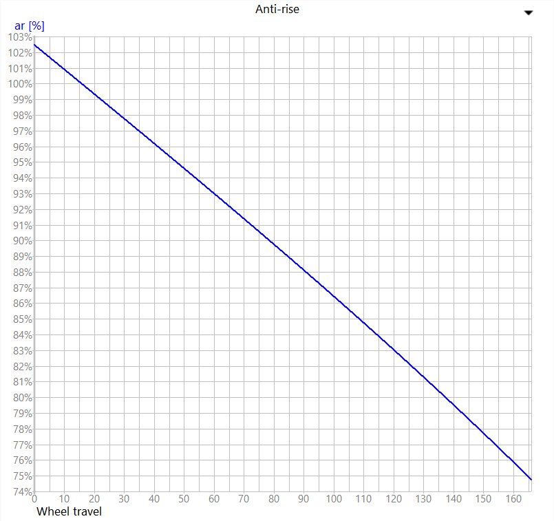
The Dirt Church has a linear decrease in %AS towards the middle and end of travel (Figure 7). I’m expecting to minimize any chain forces affecting the suspension during larger events.
- Here’s a great Vorsprung video talking about the mass of the chain and the dynamic effect a swinging mass has on suspension performance:

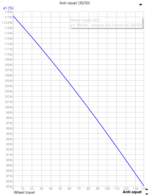
Figure 7: Anti-squat percentage vs wheel travel
Pedal-kickback is directly tied with anti-squat. That is, the higher your %AS value also the higher pedal-kickback is. This is a major issue with high-pivot designs and why an idler pulley is often used to redirect the chain direction to lower %AS and pedal-kickback.
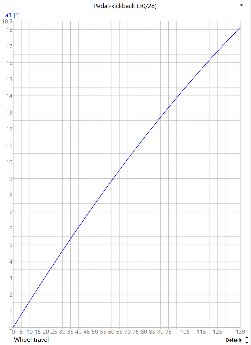
Figure 8: Dirt Church Pedal-kickback vs wheel travel
Leverage rate and wheel rate - characteristics of bottom out
Leverage rate is the inherent mechanical advantage the rear axle has over the moving shock mount. How this rate changes over the length of wheel travel is a good indication of the bike’s behavior at different parts of shock stroke.
Here are some common examples:
- Sterlings: Linear leverage rate
- Cotics + Frameworks: Progressive
- Regressive: Generally accepted as bad. Old Devinci Wilsons had a regressive rate
Figure 9 shows the leverage rate of the Dirt Church. This is how much distance the rear shock mount travels per 1 mm of rear axle travel.
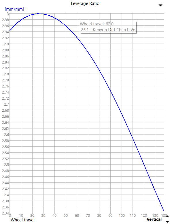
Figure 9: Dirt Church frame leverage rate vs wheel travel
Shock and Wheel Rate:
How far the rear axle moves relative to the rear shock mount at any given part of the stroke is only half of the system suspension.
The other half are the characteristics of any given shock. As shocks move through stroke, their leverage rates can also change depending on how the spring force is delivered.
Coil springs generally provide a linear rate - The amount of force to compress 1mm at 0mm stroke is the same as 1mm at 40mm of stroke.
Air springs, on the other hand, generally compress at a progressive rate. This is due to air being a compressible fluid. When compressed, the spring rate will increase as air-can volume decreases. Piggy-back shocks will typically enlarge the air can volume to try to make the progressive curve closer towards linear.
On the flip side, some suspension companies are starting to offer progressive coil springs, more common in motorsport designs, but harder to achieve in the spring lengths for bikes.
For the Dirt Church I used recorded ride .CSV data at a known spring rate to create a shock profile. I then added that into Linkage as a ‘custom’ spring rate
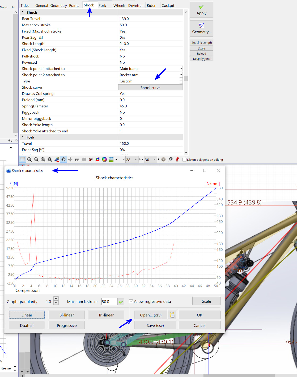
Figure 10: adding a custom shock profile in Linkage
By pairing the shock data with the leverage rate, I can anticipate the wheel rate, or how the rear wheel is moving for any given force input.
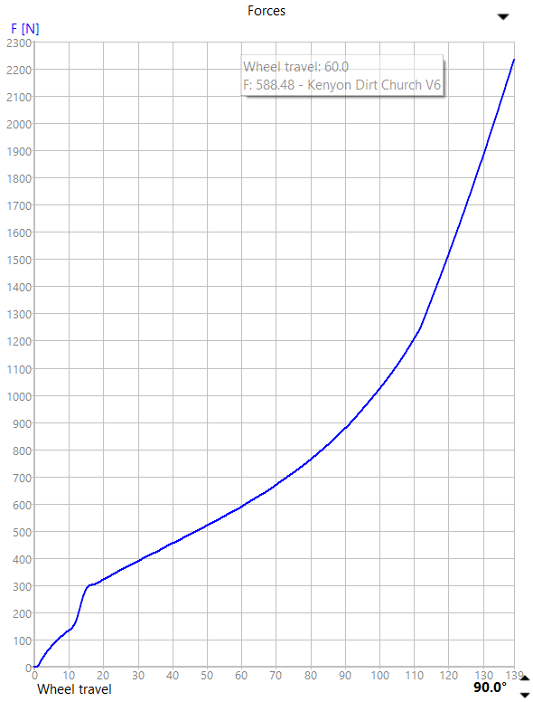
Figure 11: Rear axle force vs Wheel travel - This is wheel rate (N/mm)
The thought in the S-shape graph in Figure 11 is a sensitive small area from top-out to sag, a gentle support in the mid-stroke range, and a progressive character in end-travel events.
Anti-rise - braking effects on geometry throughout travel
Anti-rise is how the rear suspension reacts to braking forces. Similar to suspension squat when weight shift happens during pedaling, the rear suspension will extend, or ‘rise’ during deceleration under braking - this is the same weight shift that causes suspension fork dive under braking.
The Anti-rise character of a linkage can be tuned to counter this forward weight shift and help maintain the frame’s geometry under braking. The compromise is finding a balance where the suspension compresses enough to cancel the extension due to weight shift, while not compressing the suspension too much and stiffening the rear wheel which introduces brake jacking.
- Here’s a good thought from Neko’s experience when designing the Frameworks DH bikes
FRAMEWORKS 2024 - Neko Mulally Interview
- A demonstration experiment from Andre XTR:
- A good descriptor of the 0% case and 100% case:
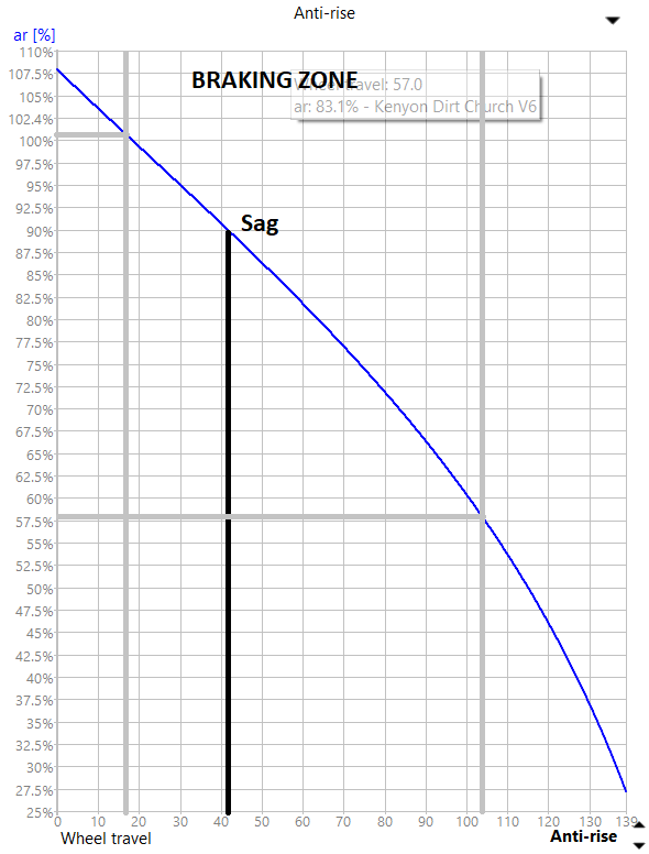
Figure 12 shows a descending character for the Dirt Church. At the sag point, ~89% anti-rise should help keep the frame geometry stable under gentle to moderate braking. As the wheel moves deeper into travel, braking forces will have less and less influence on the rear suspension, which means the suspension can remain active to maximize tire grip and I can squeeze the brakes much harder.
I coupled heavy braking with large bottom-out events for all those ‘oh shit’ moments out on the trail and am aiming for a predictable behaving bike in those situations.

Figure 12: Dirt Church Anti-rise percentage vs wheel travel
Axle Path
Axle path is the shape of how the rear axle moves from top-out to bottom-out. Rearward axle paths are said to carry speed better while vertical axle paths maintain rear end geometry for using rider inputs (pumping, jumping).
The Dirt Church uses a slightly rearward axle path, only 4mm total with 0.5mm rearward from sag to the path inflection point towards mid-travel. I’m excited to test this aspect on the trail!
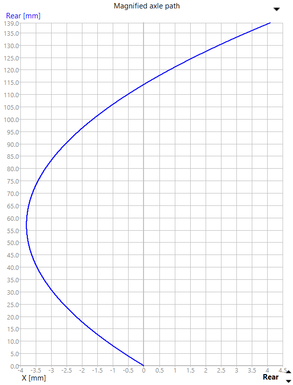
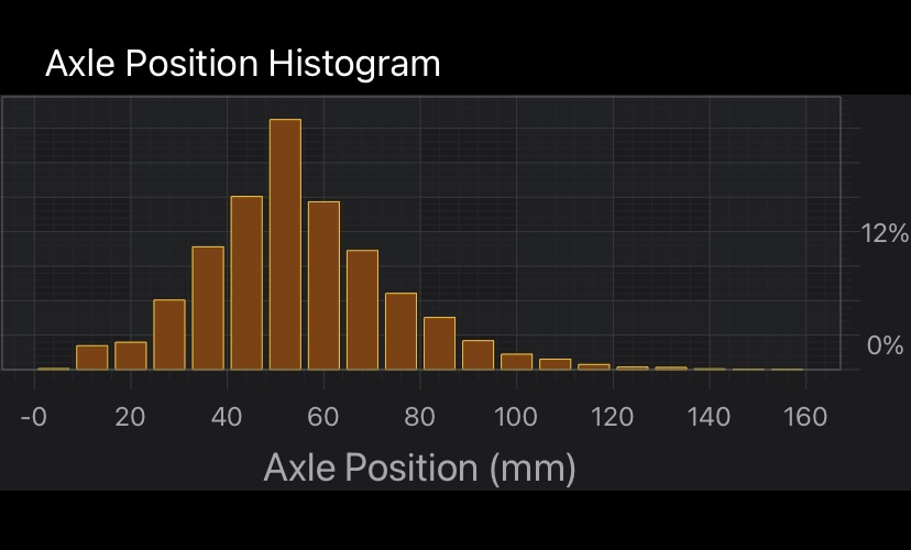
Figure 13: Dirt Church rear axle position (normalized at top-out) vs wheel travel
Thank you for reading this far - I am hoping this helps open up some ideas and discussion!
- The plan for the next post is to go through bearing selection, tubing selection, and FEA.