for those of you building with the Paragon flat mount dropouts (e.g. DR2087) are you facing the mounts after welding?
How many of ya’ll have purchased a disc brake facing tool (e.g. VAR, Park, etc) and what have you purchased?
I’ve heard mix things about the available tools. Anyone care to share your experiences, headaches, etc?
Anyone facing their mounts differently?
For context, I built with the previous version of Paragon’s flat mounts and didn’t really need to do anything. My most recent build is using the new version and there’s definitely some distortion that I should address.
These brake mounts are .5 mm oversized. If you don’t face them, they’re close enough to tolerance to work well. If you prefer to face them (and that’s good practice), put the mounts on the dropouts and face the mounts before incorporating the assembly into a frame. The dropout can beheld in a vise. The bottom of the dropout is parallel to the top of the brake mounts; put the dropout in the bottom of the vise, or on a parallel. This shouldn’t take much time, and as long as a mill is available, there’s no need for a separate facing tool.
For a nice detail, use the stainless steel version of the mounts, and don’t paint the top. You’ll get a nice surface for the brake, and no rust coming through as the caliper takes a bite out of the paint.
Thanks for your input. Here’s what I’m running into:
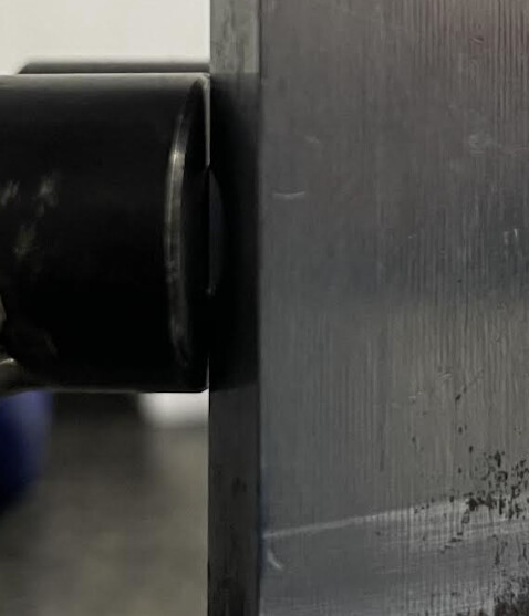
Using DR2087 and a wheel/brake combo I know works on the orig version of the Paragon flatmount dropouts, my caliper rubs the rotor. To be clear, I don’t mean the pads, I mean the rotor hits the left (NDS) side of the slot and I can’t push the caliper any more.
Measured the inside face of the NDS dropout (maybe there’s a twist that gets exaggerated when it’s clamped. There’s not).
Ran a straight edge on the outside + inside of the dropout (front to back) to make sure I didn’t massively warp things when I welded it). It’s a little wonky but less around 1/2mm off.
Checked the inside edge of the brake mounts. There’s about 3/4mm discrepancy between the two.
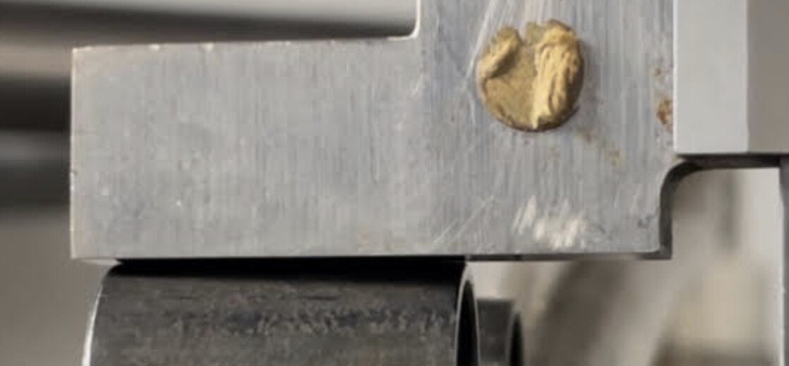
Rear mount:
Ran a gauge along the entire length of the dropout to ensure that it’s not at an angle. It’s not.
Checked placement + angle with my Farr disc brake fixture. Looks fine.
I have another set of wheels + brakes coming to check the fit with something else. But in the meantime I’m all ears for other suggestions to try to trace this back to some mistake I made.
Heya,
I read your note before you edited it. I’m going to answer so that folks that come after can get a sense of what my process was and maybe this will show where I went wrong:
I loaded the disc mounts into Le Disco, installed a dummy axle (Sputnik FWIW).
Placed the mounts in (what I think was) the right place on the dropouts.
Tacked in place (NDS face and bottom “corners” of each mount).
Front mount: Welded NDS face. Welded front side of mount. Welded back side of mount.
Rear mount: Same as front.
Checked dropout flatness as best as possible.
Ran file across the top of the mounts to ensure they’re in plane w/each other.
FWIW, I totally get why the design changed but my experiences building 3-4 bikes with the previous version were better than this one. Makes me think that I approached this a bit wrong.
To add: I’m going to pull out the Shimano docs and try to see if I have a hub/rotor that’s out of spec. Maybe it is but somehow worked on my last build.
My current solutions are: 1) braze a 1.5mm washer into the drop out or 2) Lengthen the slots in the mounts from ~7.2mm to ~8.7mm.
A bit of an interesting development that has me and a pro mechanic/friend confused.
My personal wheels are Bitex TA laced to Astrals. Rotors are centerlock Ultegra level. 160mm
These wheels definitely do not work no matter what we tried.
We even disassembled everything to make sure we didn’t have a shim or gunk making things wonky.
The best solution we could come up with is adding a 1-1.5mm shim/spacer to the inside of the NDS dropout. Not awesome.
I just ordered a set of Shimano GRX RX570s** and SM-RT64 (Deore level) centerlock rotors. 160mm.
These wheels drop in and have the extra rotor space I need. A dry fit with a GRX caliper shows me almost centered with the caliper pushed all the way to the NDS side.
I’ll need to disassemble the Bitex wheels to measure and get a better sense of what’s going on. My guess is that when I welded the dropout it deformed slightly and the Bitex hub is out of spec. The two issues probably stacked up on each other.
For the time being this is close enough and if I need a bit more room, I can hit the mount holes with a file (not optimal but whatever).
For folks that have used this version of the dropout, I’d love to know how you’re welding them up
Note:
**Holy crappers, the GRX RX570 wheels are surprisingly nice, evenly tensioned, true and dished. They’re not light but as a budget wheelset the look fantastic. They’re also on sale on the Shimano B2B.
I wonder if this is a difference between SRAM and Shimano’s flat mount spec?
It looks like SRAM specs a 2-3.5mm long slot centered at 7.05mm while Shimano specs a 1.5-2mm slot that starts 5.55 +/-0.4mm from the dropout face.
The PMW boss slots are 2mm long but I can’t recall or easily find what their center is. If it is 7.05mm like the SRAM spec then they wouldn’t be able to hit the 5.55mm Shimano calls for - they’d max out at 6.05mm. Whether or not that’s what you’re seeing, I’m not sure.
I hope my 2 cents will help to clarify: Our flat mounts are manufactured to Shimano specs. We got these specs from Shimano, long before SRAM published their spec. In some ways, the SRAM spec is more forgiving, because of the broader dimensions. In some ways, it’s a headache, as documented by @ElysianBikeCo . The proof is when you put Shimano components in, it all works.
We would like to give builders more room, but in this particular design, there’s not enough physical space to do so without a major overhaul. We have already tweaked this dropout, with comments from builders. At this point, I feel this design is solid, and any component designed to Shimano specs will work. The big problem is a builder or rider may not know if the components they spent a lot of money on are going to work. Unfortunately, I don’t have an answer for that, other than buy Shimano, or confirm with the manufacturer that they follow Shimano’s specs.
A note on fixturing: These brake mounts and dropout are meant to be self-locating; that is, the relief in the dropout positions the brake mount in the correct position. Clamp the mount to the dropout and weld or braze it. If you have a fixture, there’s no harm in using it, but if there’s a conflict between where the fixture positions the mount and the locating features of our dropout/mount, the locating features are the correct position. This is particularly helpful for hobby or beginner builders on a budget, no expensive fixture required.
Also, see my previous post in this thread about milling the brake bosses after fabrication.
Thank you @liberationfab for posting both SRAM and Shimano specs.
Thanks for clarifying that all @mark_pmw! It’s wild that the two major suppliers don’t agree on a unified FM mounting spec and very annoying that the onus is on us to accommodate that.
@ElysianBikeCo The other thing I’d think to check is the position of the rotor from the endcap of the hub. The inner face of the rotor (closest to the hub) should be 18.75mm from the endcap for a 142mm TA hub.
@mark_pmw Mark, I hope that my previous posts didn’t come off as implying that I think there’s something inherently wrong with the drop outs.
I had this conversation with my mechanic and we both agreed that the best way forward at this point is to confirm fit with a set of mid-level Shimano hubs that have been measured + “approved.” If I do that I can at least absolve myself of some blame and sins.
Yeah, I’m gonna go that route. My “eye-crometer” and an ill-placed ruler tells me that I’m closer to 17mm. If you add that to some welding technique issues and all the other stuff I could be in that “no go” range with this specific hub/disc combo.
Whatever the issue, it’s been a “fun” headscratcher and definitely a learning moment.
Thank you both for adding a bit of information to the thread! It’s really helpful. I’m sure it’ll help out another builder at some point.
PS: I updated the thread title to better suite the content.