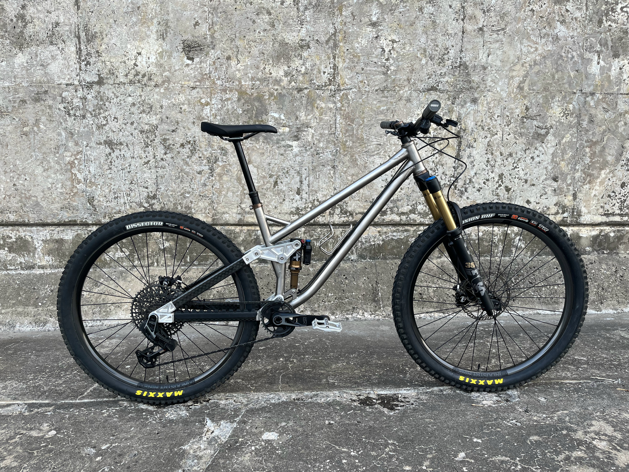
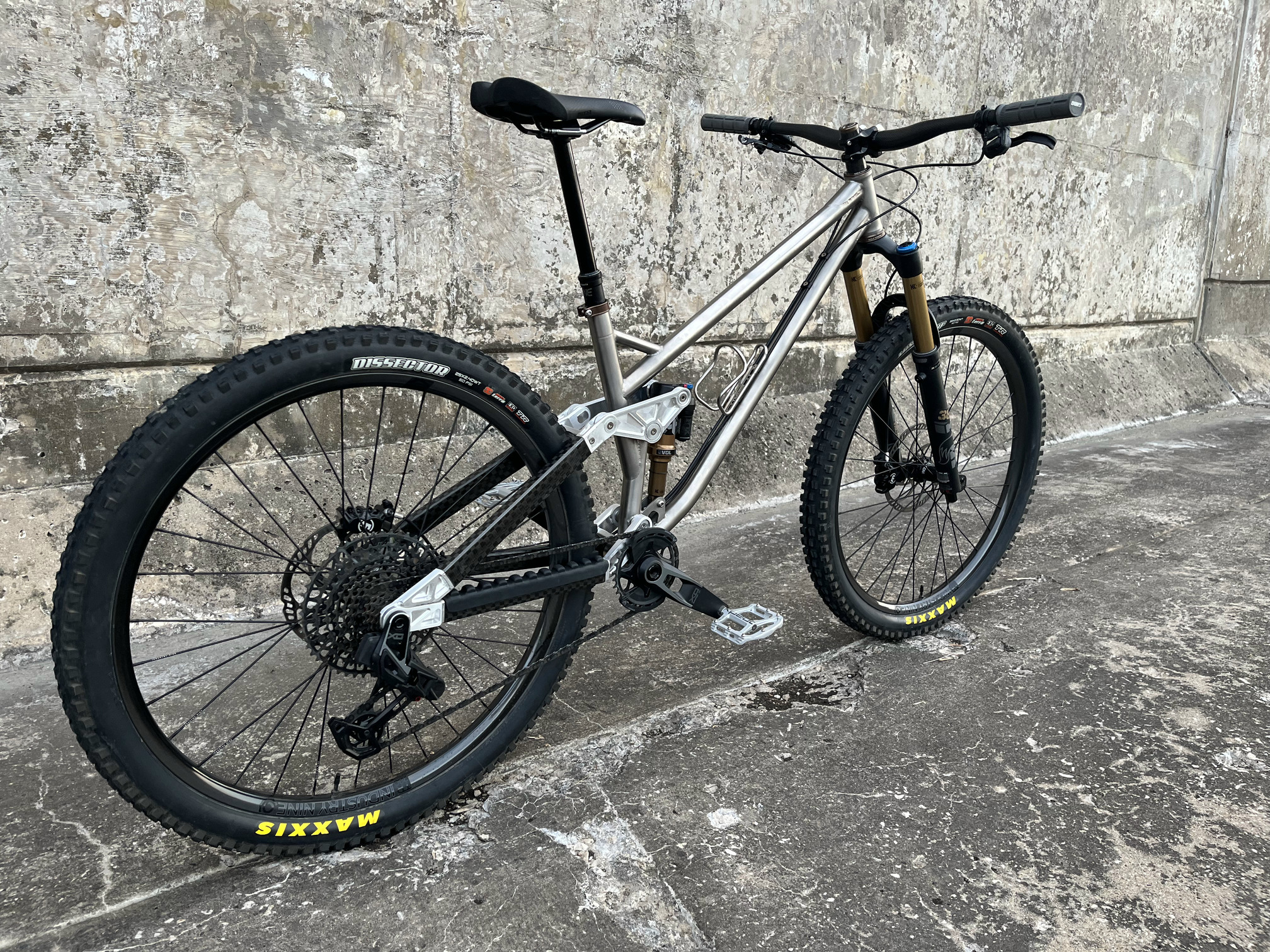
I meant to start a build thread for this awhile back but that clearly didn’t happen in time! So instead of documenting the progress of the bike, I thought it’d be interesting to share the finished bike and work backwards though the process.
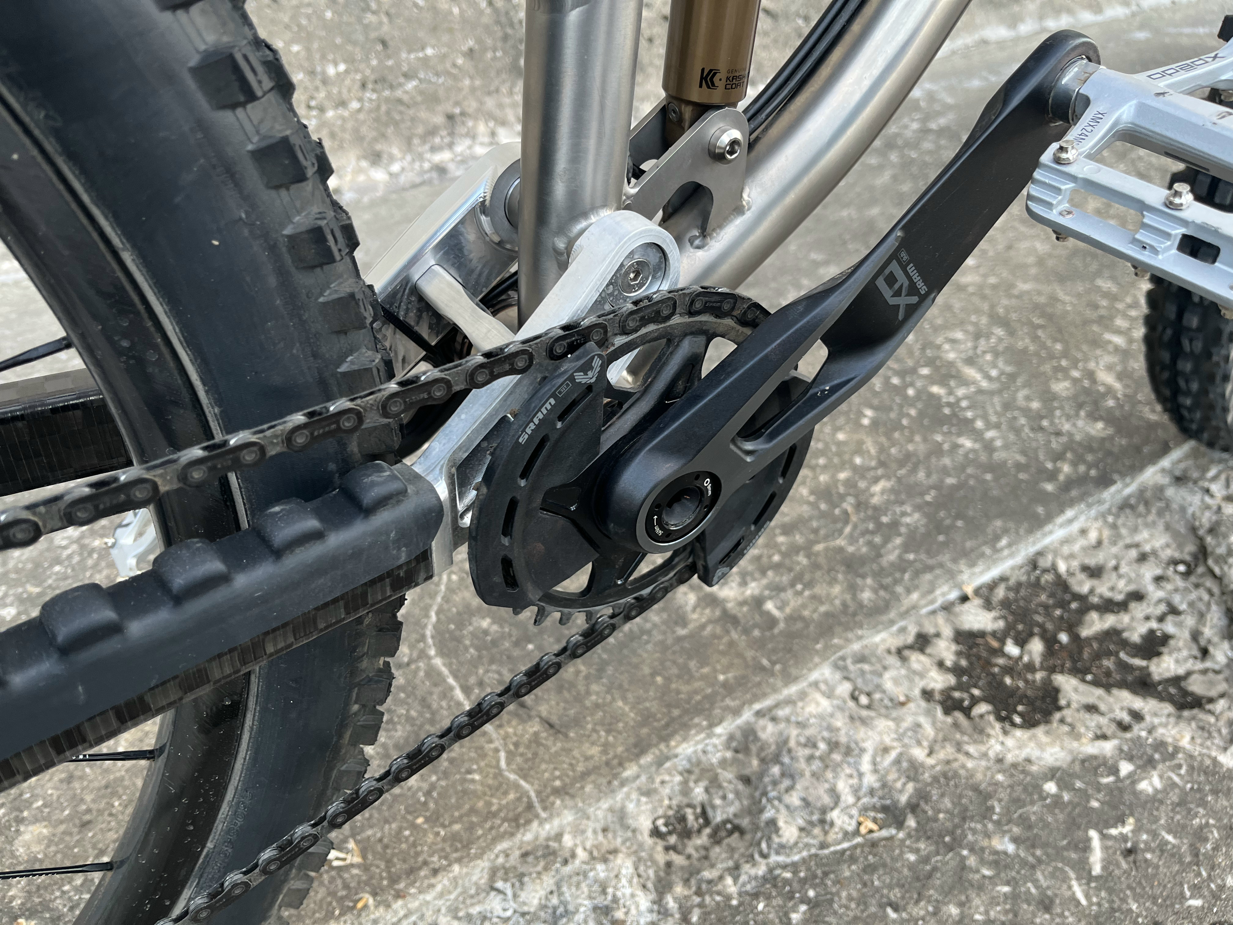
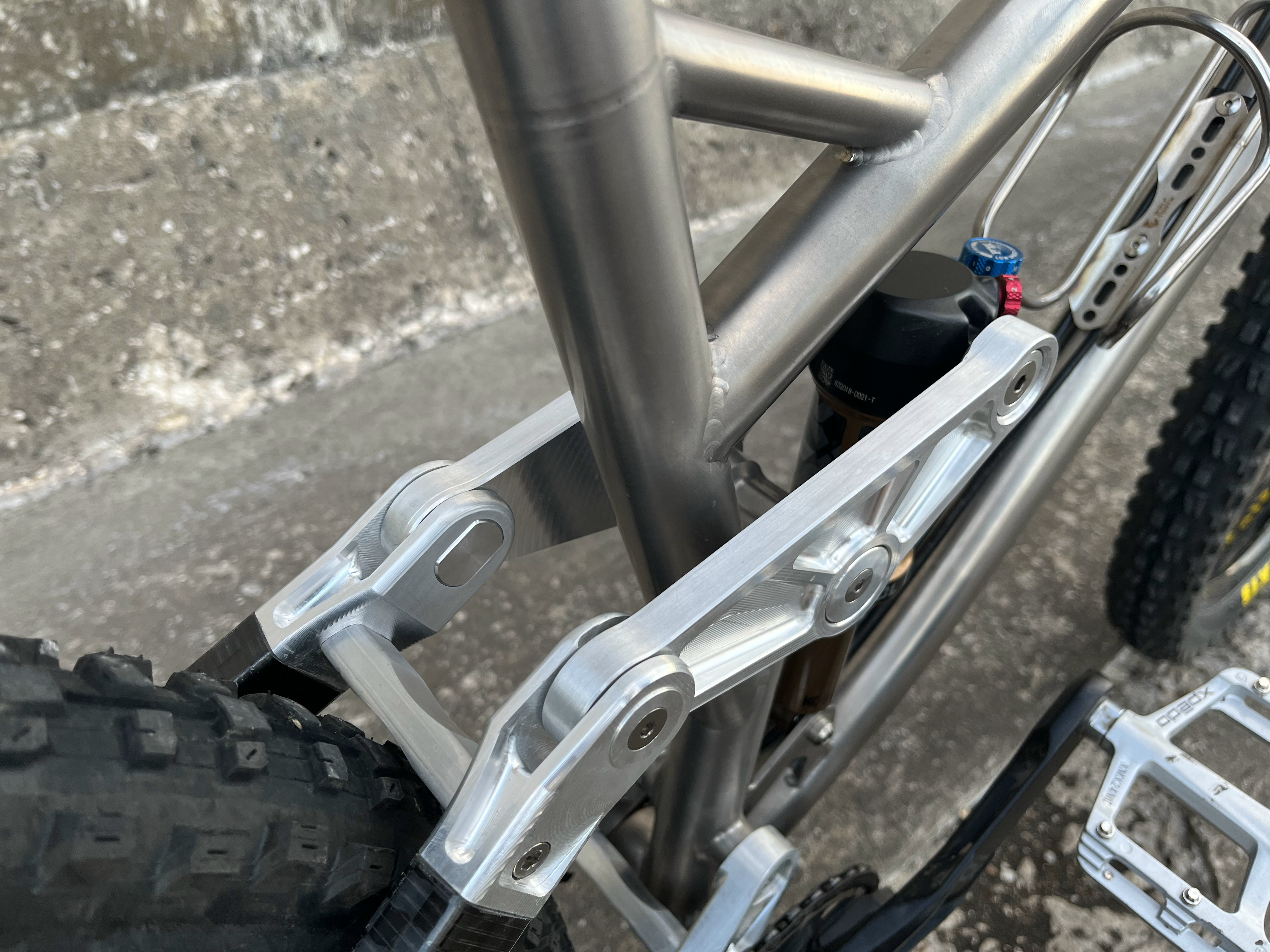
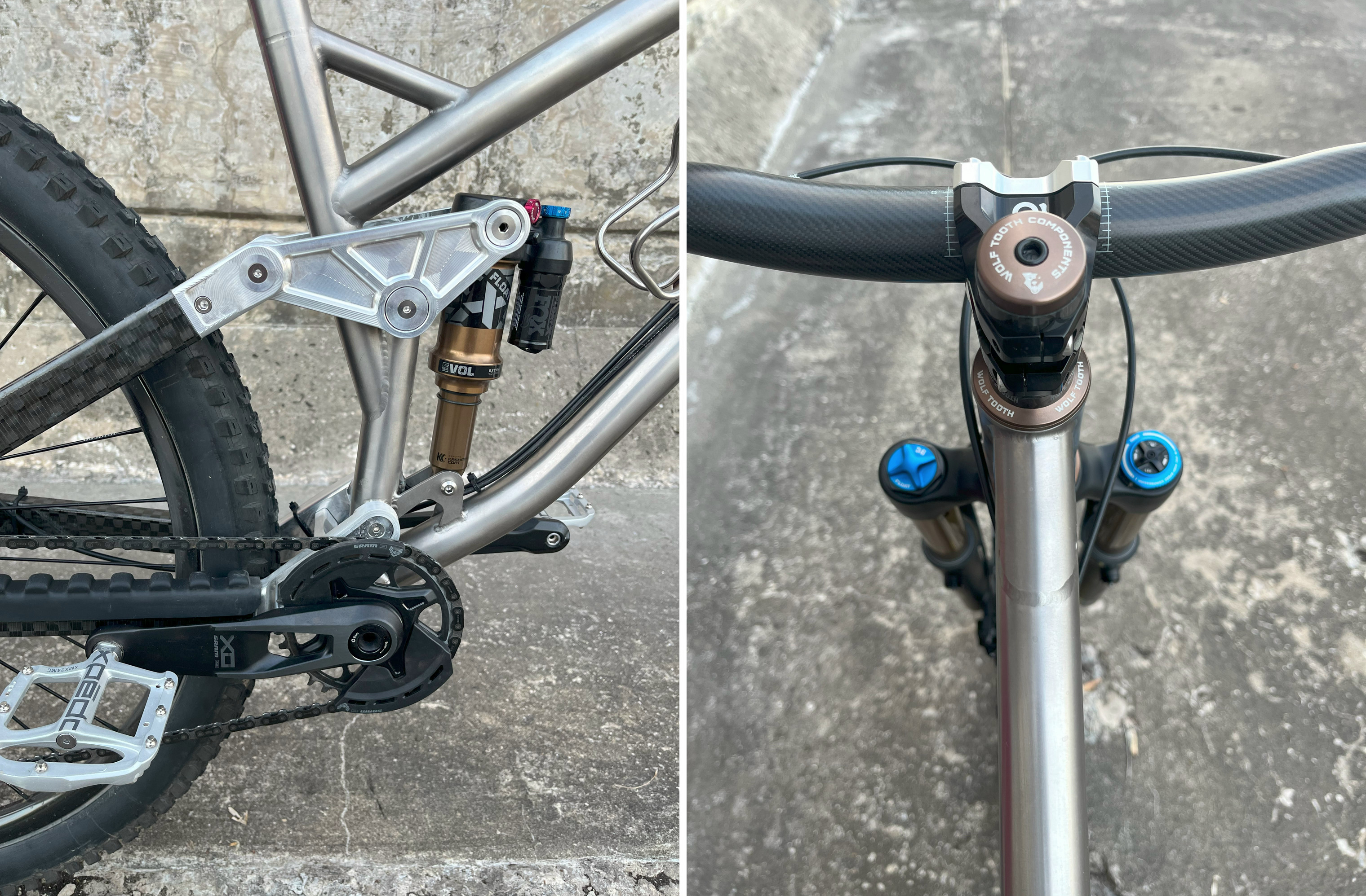
The front triangle is titanium and the rear is roll wrapped carbon fiber tubing bonded to machined aluminum lugs. The suspension design uses a split pivot that’s common on Trek and Salsa frames. This greatly simplified part design and kinematics. I wasn’t really looking to challenge the status quo with geometry, instead I tried to focus on having a reliable and predictable platform. I originally designed around the UDH and the T-type was released right when I was piecing together components so I couldn’t help myself. I’ve been putting laps on the bike for about a month now and have been really happy with it so far. When I get a chance I’ll follow this post up with a couple more where I can dive into the details.
Wow! This is amazing! So many different construction methods are represented here.
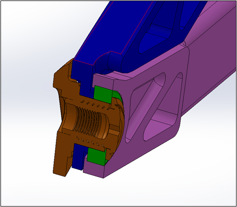
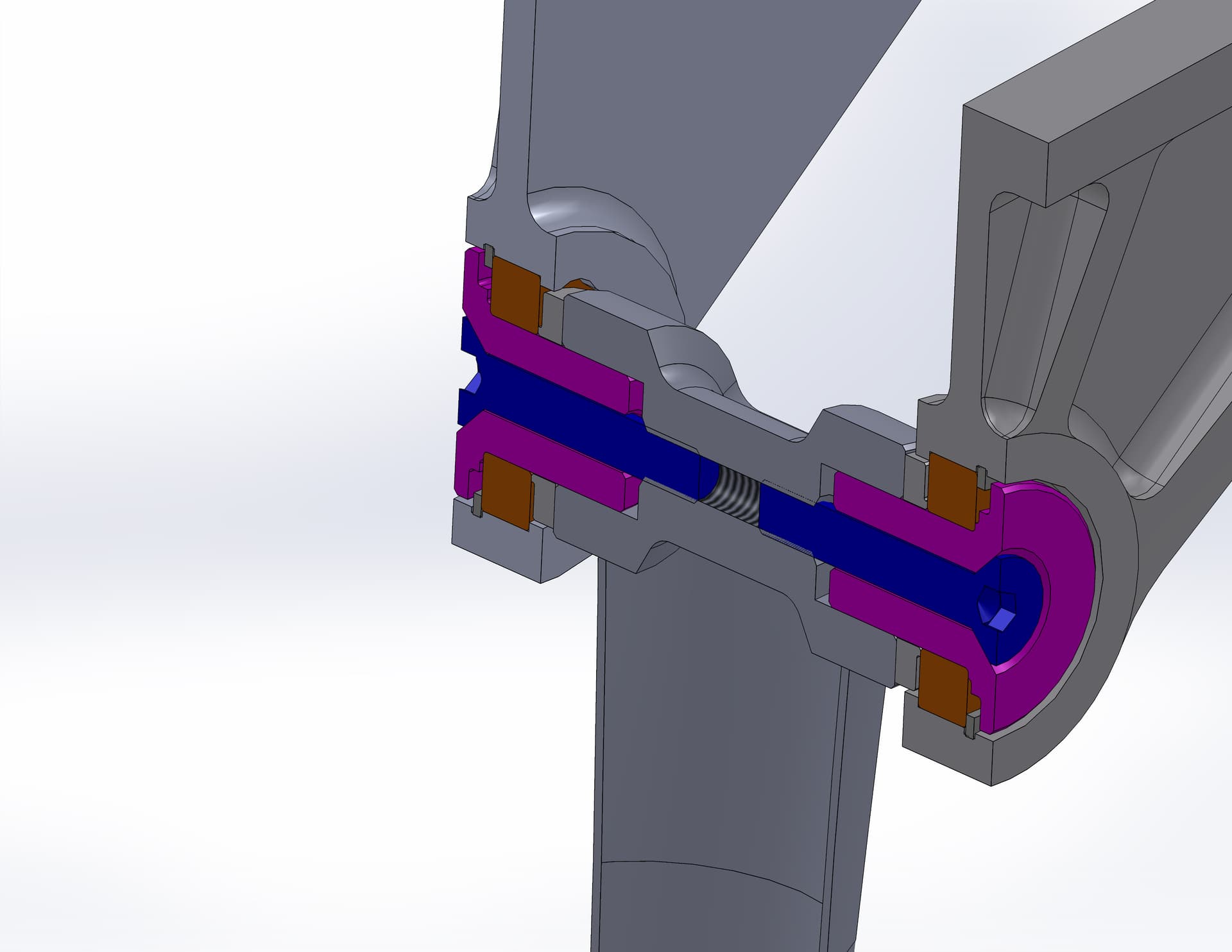
I am curious about the split pivot design. Do you have a cutaway view of the pivot? Do the bearings rotate directly onto the rear axle? How the transmission rotates (or does not rotate) is breaking my brain.
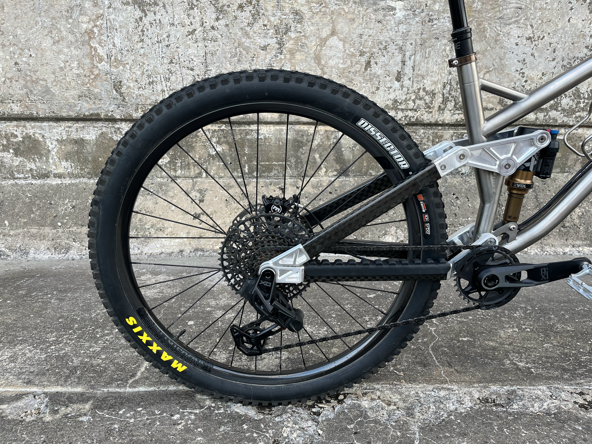
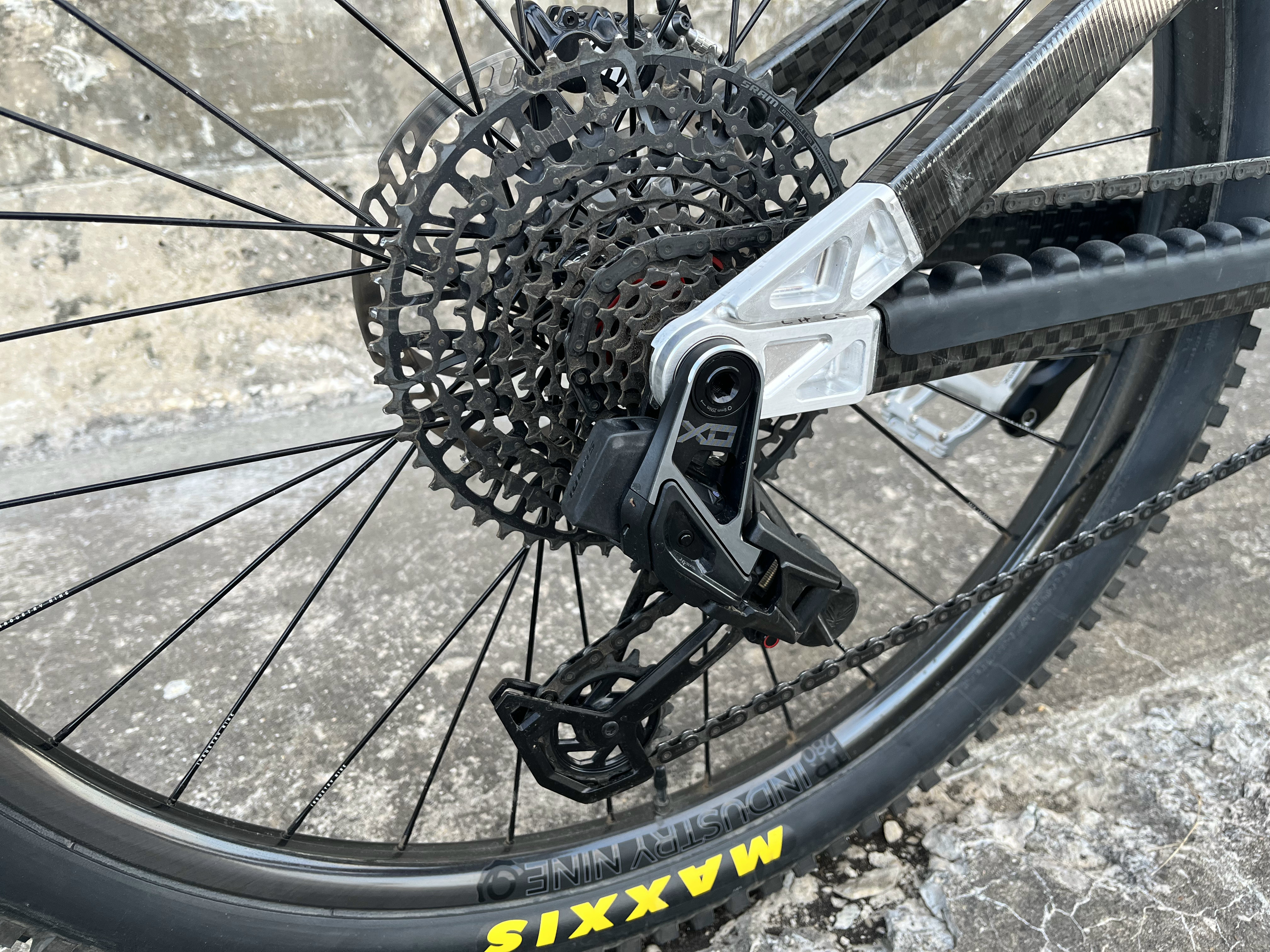
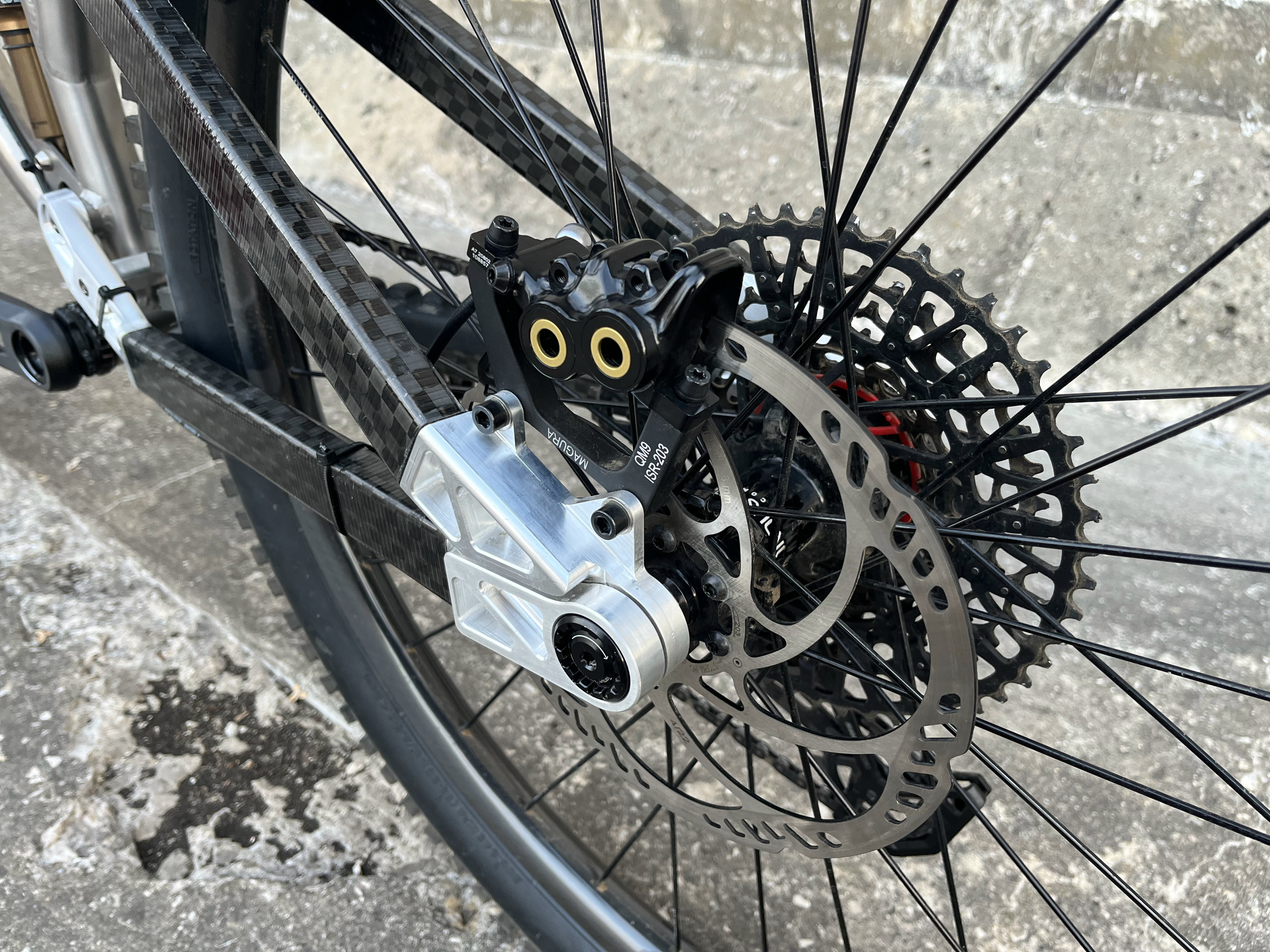
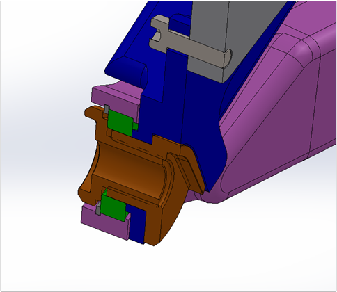
Basically, the seatstays, inner bearing races, axle, and UDH/Transmission are fixed to each other. The only things that rotate independently are the chainstays which have the pivot bearings pressed into them. The bearings have a 20mm ID so they work with the transmission bushing or UDH. On the non-drive side there’s a two-piece threaded dropout that also acts as a reducer for the 12mm axle. I just bought this from Trek rather than making my own.
The Sram spec isn’t very forgiving on the drive side for packaging. I would have liked to have more material in places and been able to increase the running clearance between the chainstay and seatstay. There also isn’t much space to mechanically retain the bearing so you’re relying on a good press fit. These are the cross sections for the drive side (with the UDH) and non-drive side.
The carbon tubing is an off the shelf profile from Rockwest (0.76” x 1.34” outside dimensions). They have a whole catalog of bike specific tubing and can make custom tubes, but this is just one of their stock non-bike shapes. As such, I don’t think the layup schedule is really optimized for what I’m using it for, but the relatively large cross section seems to make up for that. I used a carbon hacksaw blade and the park tool saw guide to cut them to length. The mating surfaces get sanded with 120 grit, cleaned, and bonded to the aluminum lugs with 2-part Hysol epoxy. There are glass beads mixed in to control the bond gap. I’m a little worried about galvanic corrosion since it’s raw aluminum and carbon but hopefully the epoxy provides enough of a barrier for now.
I really liked this construction method for the rear triangle. The straight carbon fiber tubing is comparatively inexpensive when looking at the molds required for more complex geometry. It can be easily cut to length for different frame sizes or suspension designs. Plus, you save a little unsprung weight and there’s no need to worry about distortion due to welding so the alignment is as good as the jig you use.
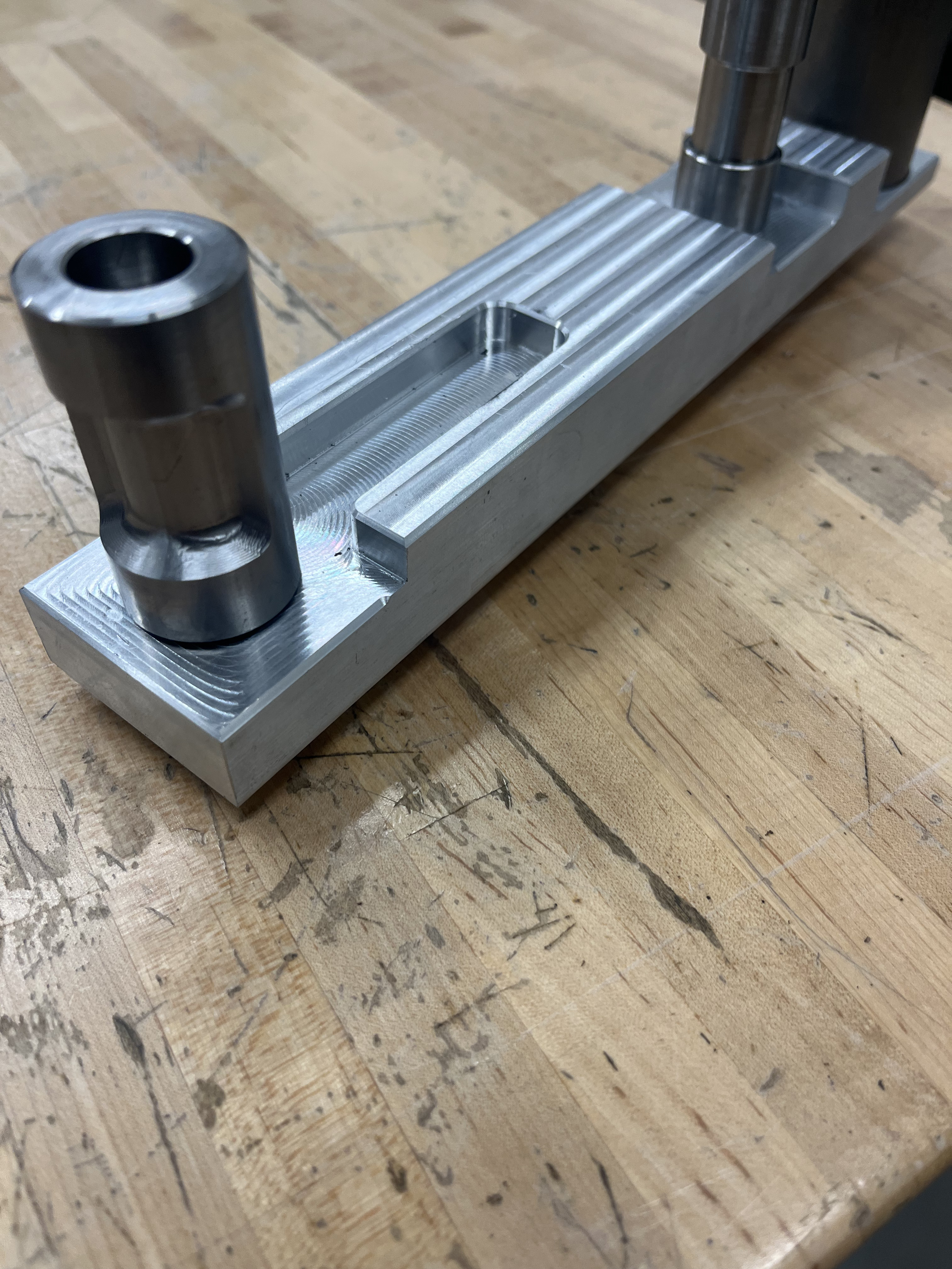
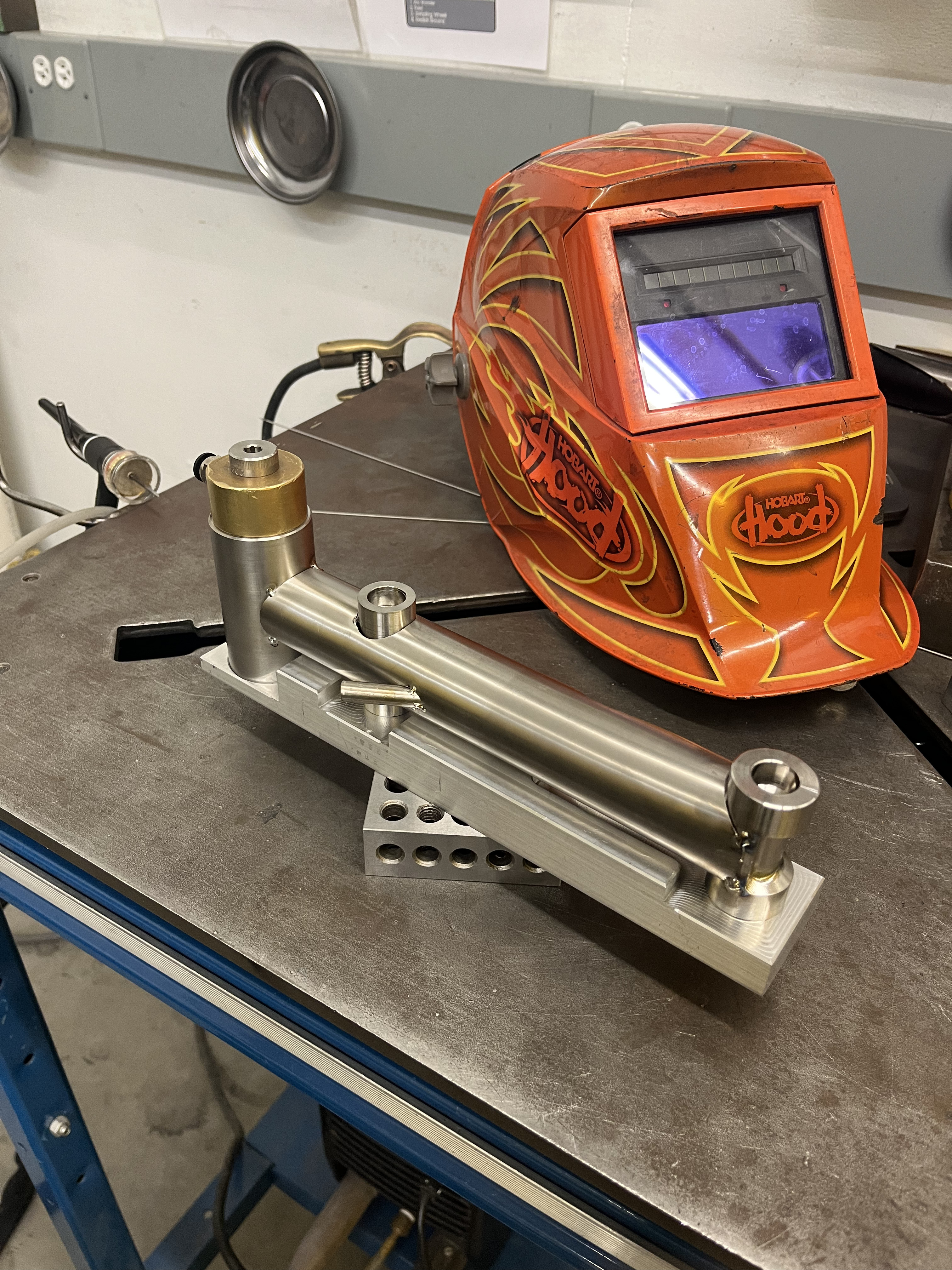
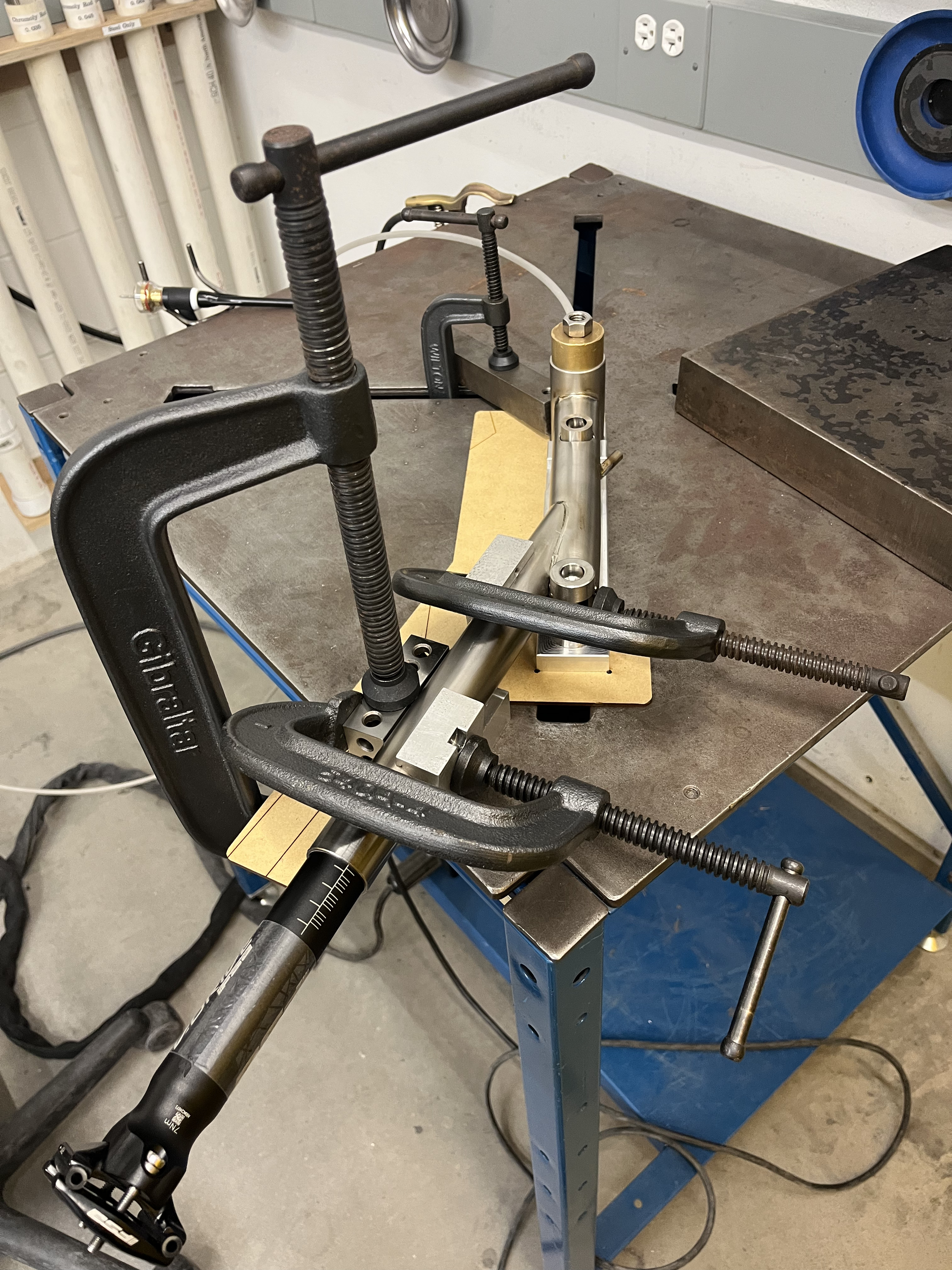
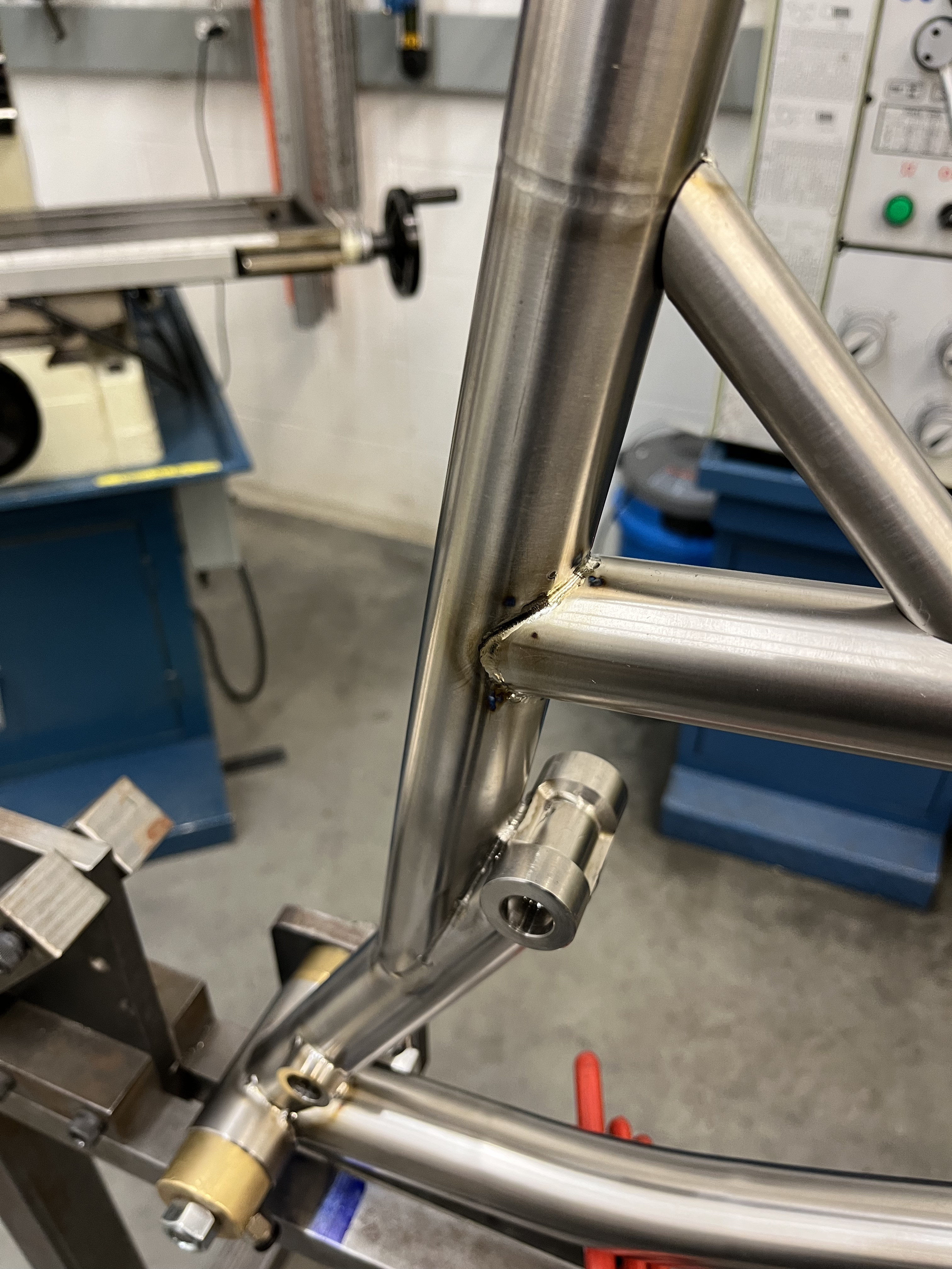
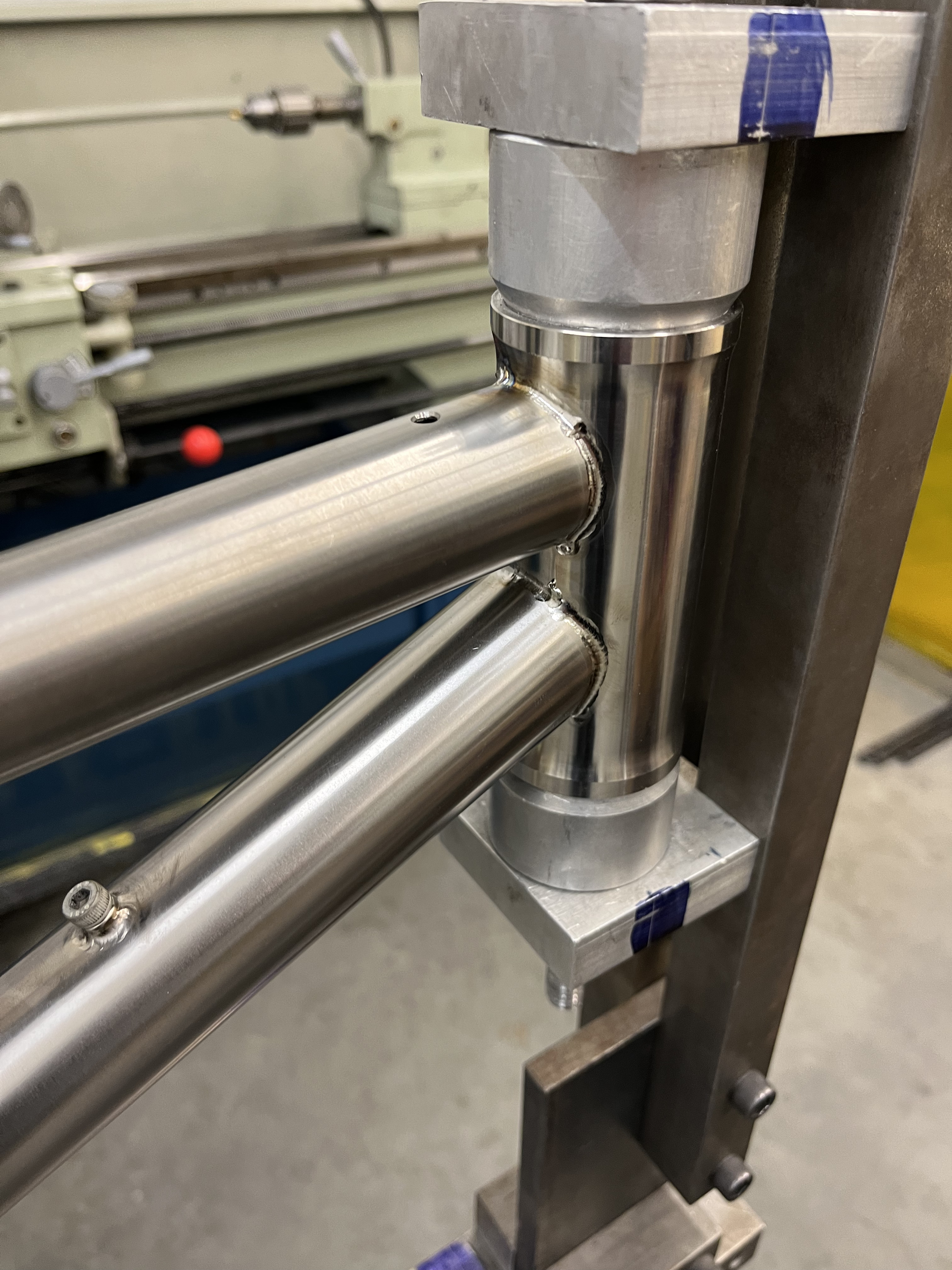
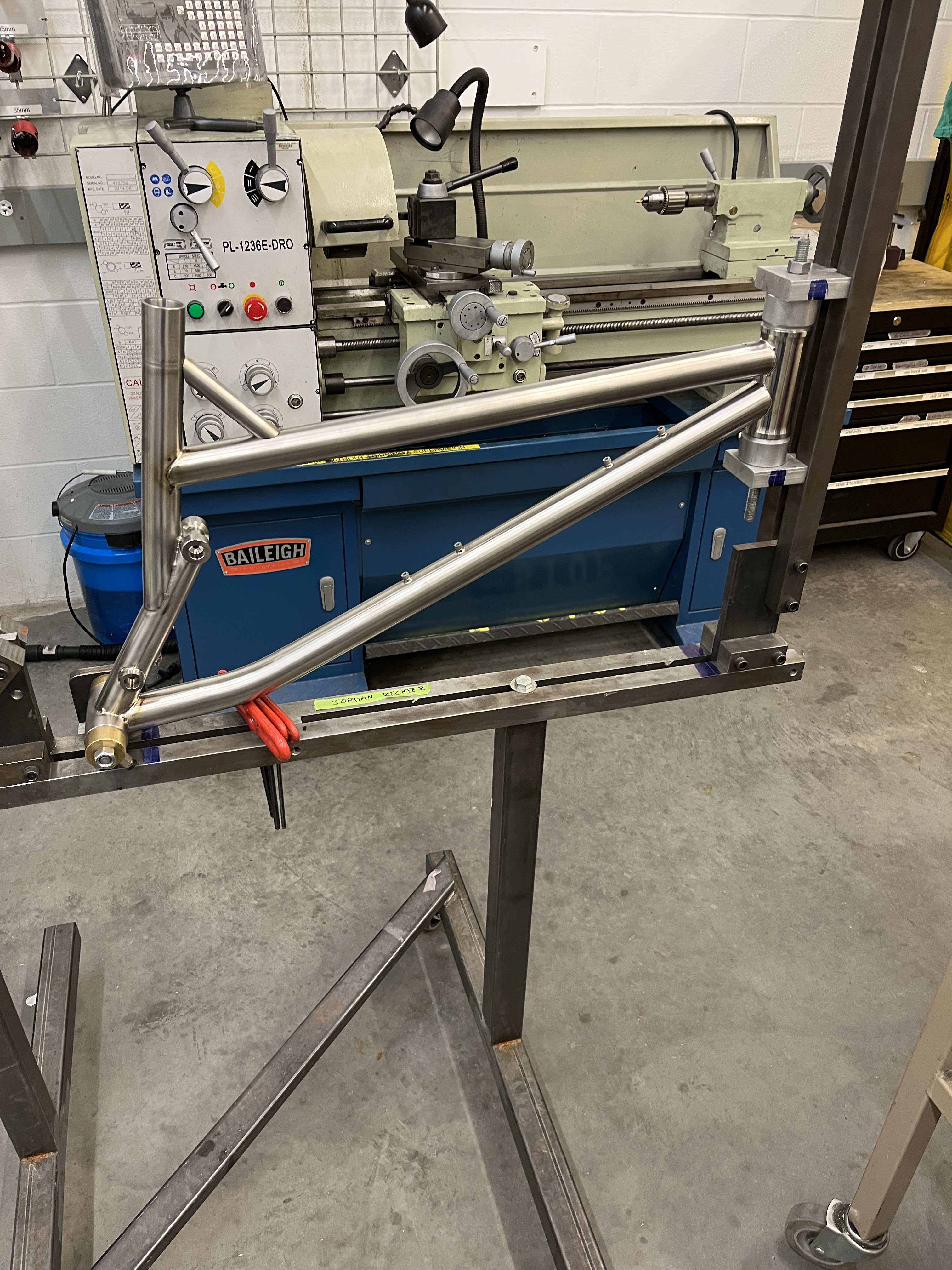
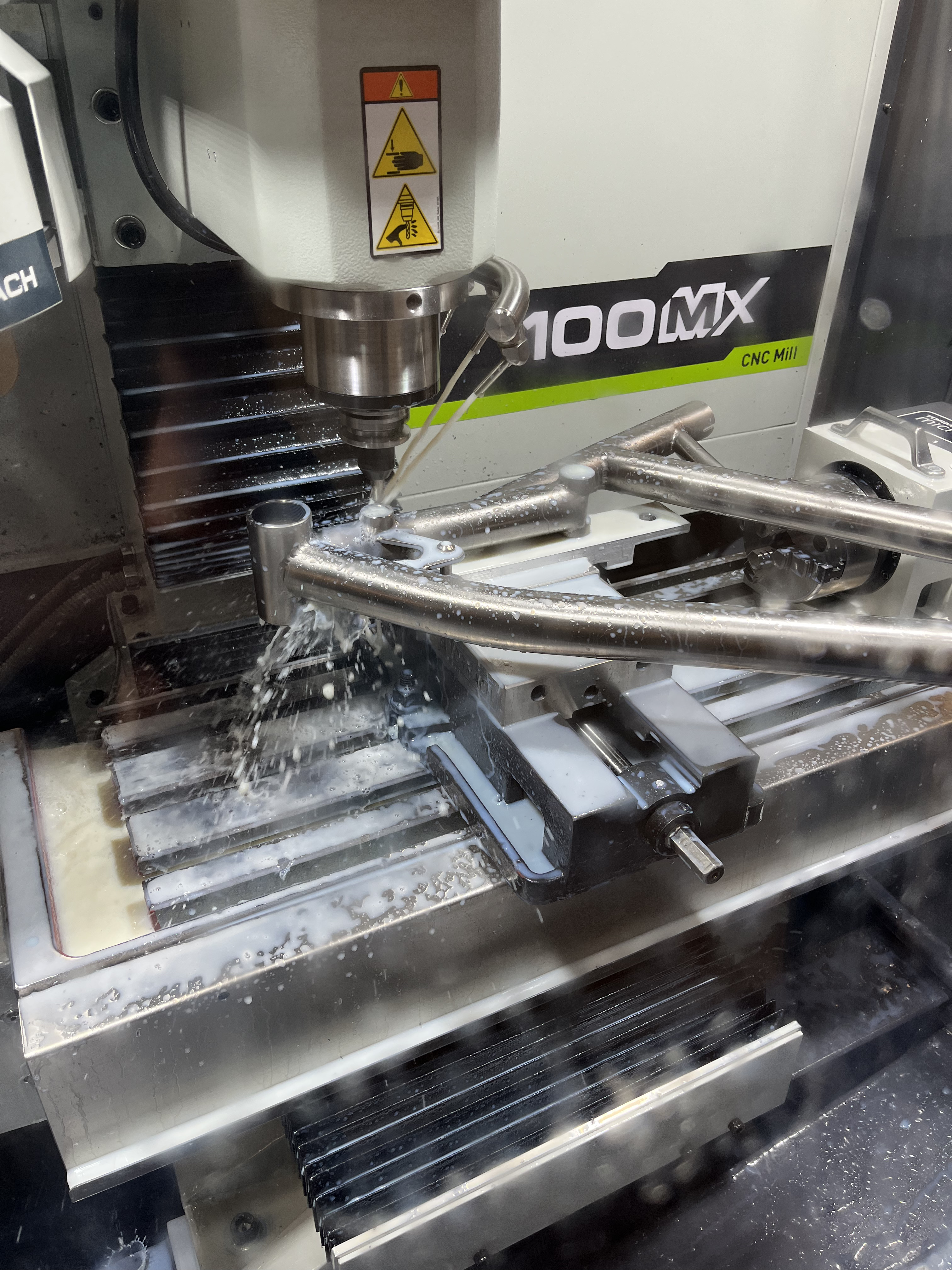
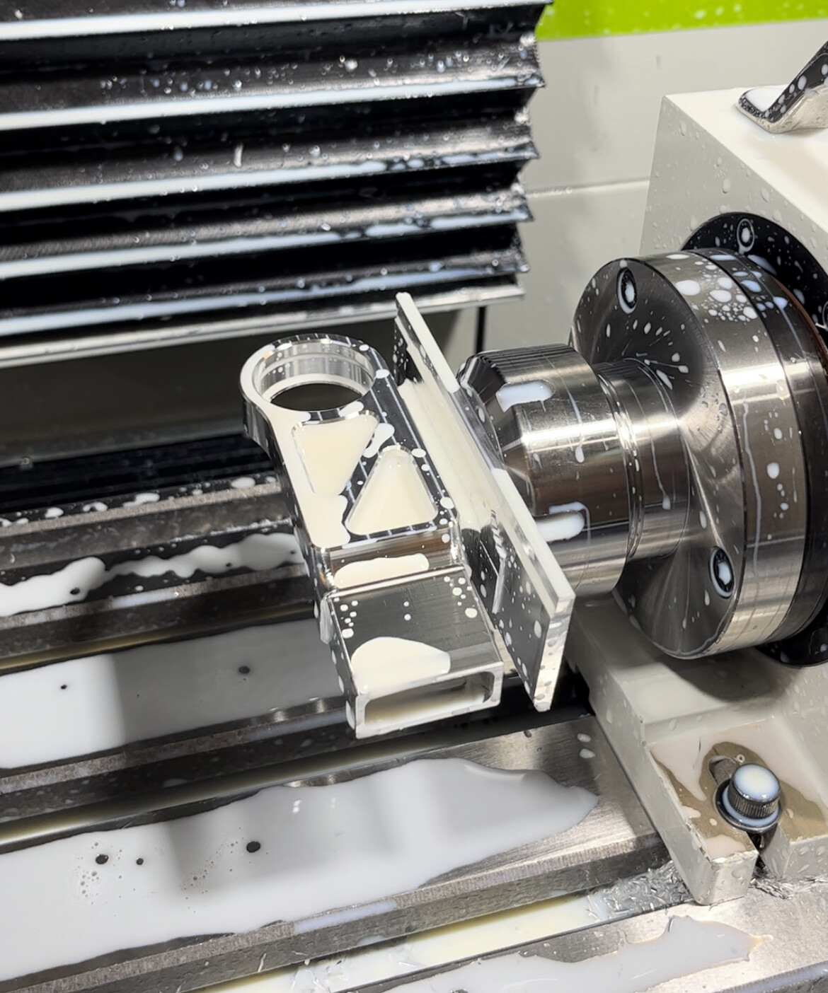
Here’s some pictures of the front triangle fabrication. Seat tube was probably the trickiest part. I machined a fixture to keep the BB and suspension pivots aligned and then used some 123 blocks and a template to fixture the upper portion semi accurately. The lower tube was basically swiss cheese by the time I was done. In addition to the visible cutouts, there’s a large one that aligns with the seat post for additional dropper clearance. I did the fusion pass on everything then located that in the frame jig. I left some stock on the pivots so I could come back and bore/face them after finish welding the frame. Kind of a nerve-wracking operation but I snuck up on the dimensions and luckily averted catastrophe.
I don’t have any immediate plans to make more. I’ll probably enjoy this one for a while, see how it holds up, and make changes if issues arise. It’s also a pretty modular design so if I wanted to tweak the geometry or kinematics I think I could swap components fairly easily.
This is incredible work, thank you for posting! How has the rear triangle held up to abuse? What insertion do the machines aluminum parts have into the carbon tubes?
Insertion is an inch for both the chainstays and seatstays. I did some napkin math to make sure I was in the ballpark based on the shear strength of the epoxy, but it’s still a bit of a swag. Everything has held up great so far though. I’ve been happy with how stiff the rear triangle is too. I was half expecting some deflection or tracking issues with hard cornering.
Nice, thanks! That’s a nice setup you have with the rotary axis. I was just brainstorming how I was going to get some of these angles and that would be a great way to do it:)
Thank you Kova for reviving this thread, it’s a bit before my time so I missed out on it but this Ti bike is genuinely one of the nicest I’ve ever seen!
Thanks! I really enjoyed the build and the bike has been a blast to ride. No real issues to report and I’ve been able to put some hard miles on. Happy to answer any questions here. If I get around to it I’ll dig up some more information and do another post about the design process I went through too.
Sounds amazing. Happy to hear that this bike is still alive. Did you weld the ti frame on the jig, or just tag it up and weld the rest on the table. How straight was the frame after welding, im unfamiliar with titanium welding. I also saw your jig on the cnc machine, great work on that. Did you manage to machine both sides of the bearing races on one go, or just flipped it to machine the other bearing race? I know kavenz machines the whole bearing race at once and inserts circlips to locate the bearings. This way they get concentricity on both bearings!
Ps. Im planning on making some metal frames and perhaps using the same construction method for rear triangle as you did here. I can’t express it enough how cool it looks. Our first prototypes should definitely have that construction tried out.
Id love to see the design process too if you someday get the motivations to do it
I’m not OP but I can tell you that welding Ti while it’s still in the jig is preferable to tacking it up and welding after. My Dad knows some Ti welders and that’s how he says they do it.
Yeah, I welded as much as I could in the fixture to limit warping. The frame fixture is a copy of the one designed by Black Sheep Bikes. It gives really good access for welding on both sides. The seat tube, BB and suspension pivots were welded up as a separate sub assembly though. Next time around I’ll use a heat sink on the top of the seat tube. That part ended up out of round and made reaming kind of challenging. Thought about trying a bonded fiberglass sleeve for the seat tube as well. It would eliminate welding the collar on and be a lot easier to finish to final diameter.
I went back and forth on the pivot design and how to manufacture them. My original plan was to use hardware from a Transition Sentinel and then just have the frame bored to 16mm at each pivot. I could have done this all from one side like you mentioned to keep everything aligned. Instead I made custom hardware, tapped the center of the bosses and machined the faces and bores completely after welding. I had a fixture so everything stayed pretty well aligned. Good enough for a bike at least.