Hey all! I’m pretty new in the ways of designing for additive manufacturing. I’ve been noodling on the idea of a front dropout that integrates flat mount bosses into the taper of a Columbus FBRN16T465DSK001 fork blade. I’d love thoughts on:
If this is a good application for 3D printing
Smart methods of anchoring the FM caliper (maybe like the OPEN U.P. “U-Turn”?)
Methods to sculpt the part in F360 to make it look nice
According to Specialized, the holes are closer than the usual flat mount standard, so that they can make the end section of the fork leg hollow, in order to save some weight. Not sure if it is worth it to make this non-standard design, when most other areas are standard.
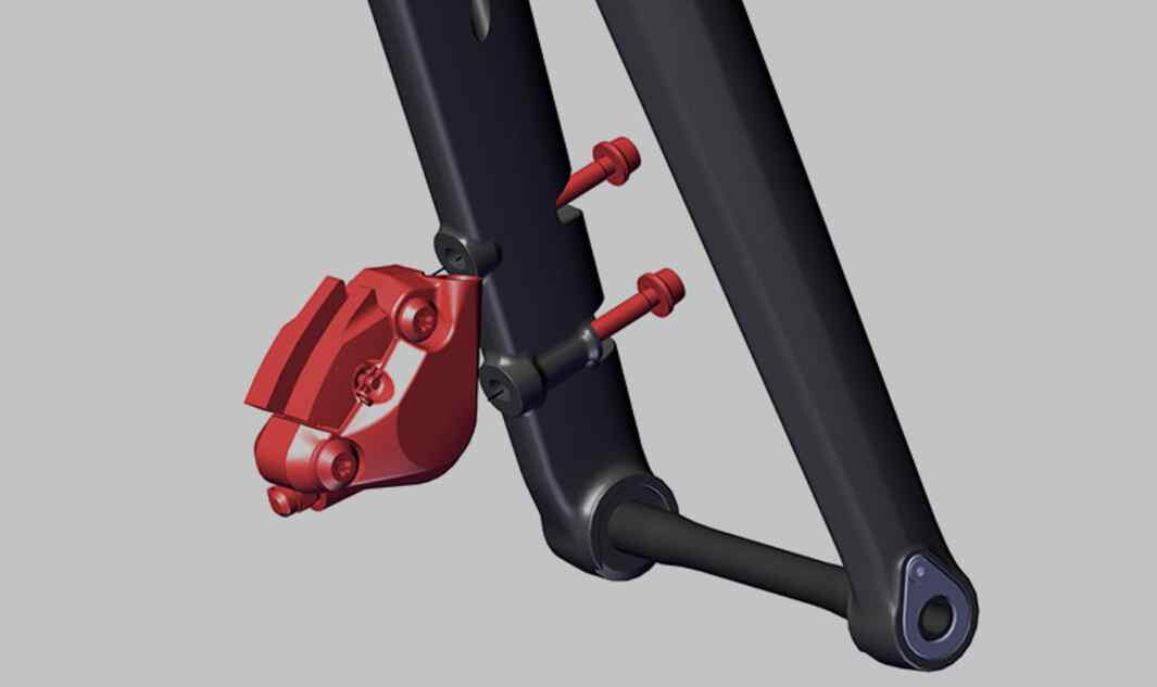
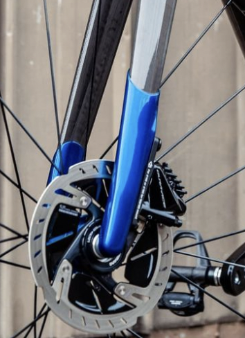
The U-Turn is the first fork truly optimized for flatmount brakes. Standard flatmount front brakes include an adaptor to switch between 140mm and 160mm disc rotors. But nobody should ride 140mm rotors in the front, so it’s a feature without a benefit at the cost of weight, stiffness and complexity. The U-Turn’s Smartmount is a direct-mount with thru-bolts without adaptors, just like the rear brake. The position of the mount is adjusted to perfectly match 160mm rotors. Lighter, cleaner and safer.
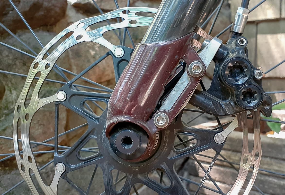
I like the idea of borrowing the rear design with ovalized holes, like the Open fork. That way you don’t have to have threads in the 3d printed part or the fork legs. The goal would be to remove as little material from the fork leg as possible and the 3d printed part can act as reinforcement.
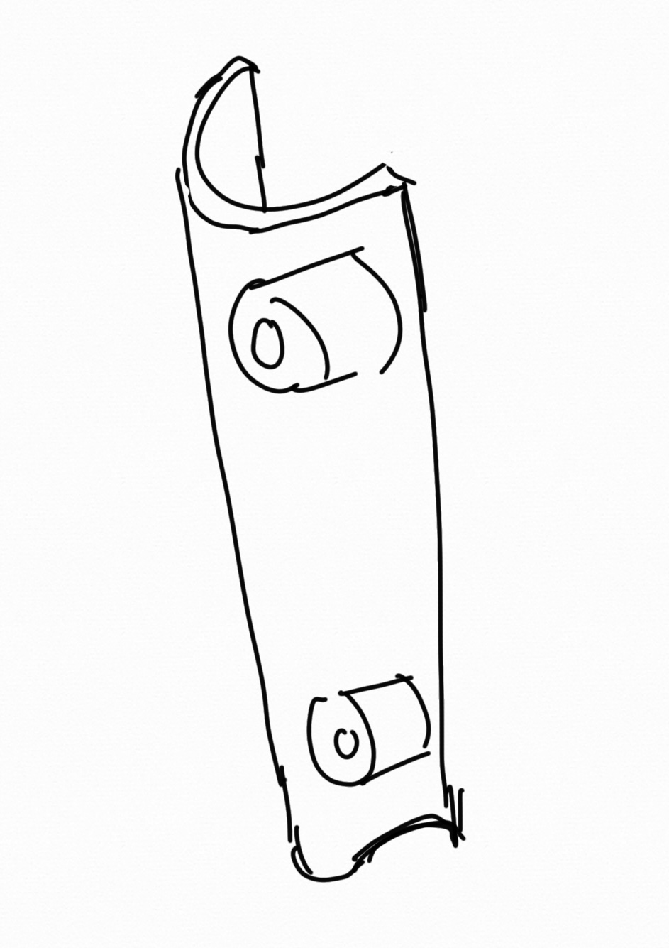
Something like Daniel’s drawing would be a tidy solution if the mounts are ovalized. Ideally the location would allow 160 rotors with no adapter and 180 with a rear adapter.
Thank you for such a thoughtful response!! I also thought about the design you sketched out - I need to draw it up and see how it all lines up. A big goal with this was to not have to drill/mill into the fork stays.
I think using a “rear” style FM caliper mount is for sure the way to go. Like you and @manzanitacycles suggested, threads in the fork is a big ol bummer. I’ve had some forks start to strip there and it is not confidence inspiring.
Unless I’m not visualizing it correctly, you’d have to design the part as an integrated solution to a specific fork build. It wouldn’t work like the Willits tab from PMW, which can be adapted to lots of designs.
It looks like you plan to make a segmented fork. Do you already have fork length, tire clearance, and offset in mind?
Agreed, seems unfortunate to have to drill holes into a perfectly good tube… This seems to be the fundamental problem with flatmount.
I don’t think it’s a stretch to say flatmount is designed for carbon bikes. That is why they are such headaches for metal builders. To be fair, it appears to be an issue for production bikes as well .
This is why I think PVD’s flatmount system is a potential solution for metal forks + flatmount:
And to address the elephant in the room, I don’t always agree with PVD’s ideas or the way he expresses them, but I respect the amount of thought he puts into his work and his documentation. This forum is open to everyone and their ideas, so long as they are discussed respectfully!
If I opened a can of worms, I sincerely apologize @liberationfab!
Totally agree! The IS-to-FM adapter is pretty slick, but I don’t know if the world is ready for that It does seem like it would be clunky on a more svelte fork.
The “rear style” mount looks more promising, I might have to do some reverse engineering to get it to stick out a bit less. Still gotta noodle around in the model to figure out what makes the most sense.
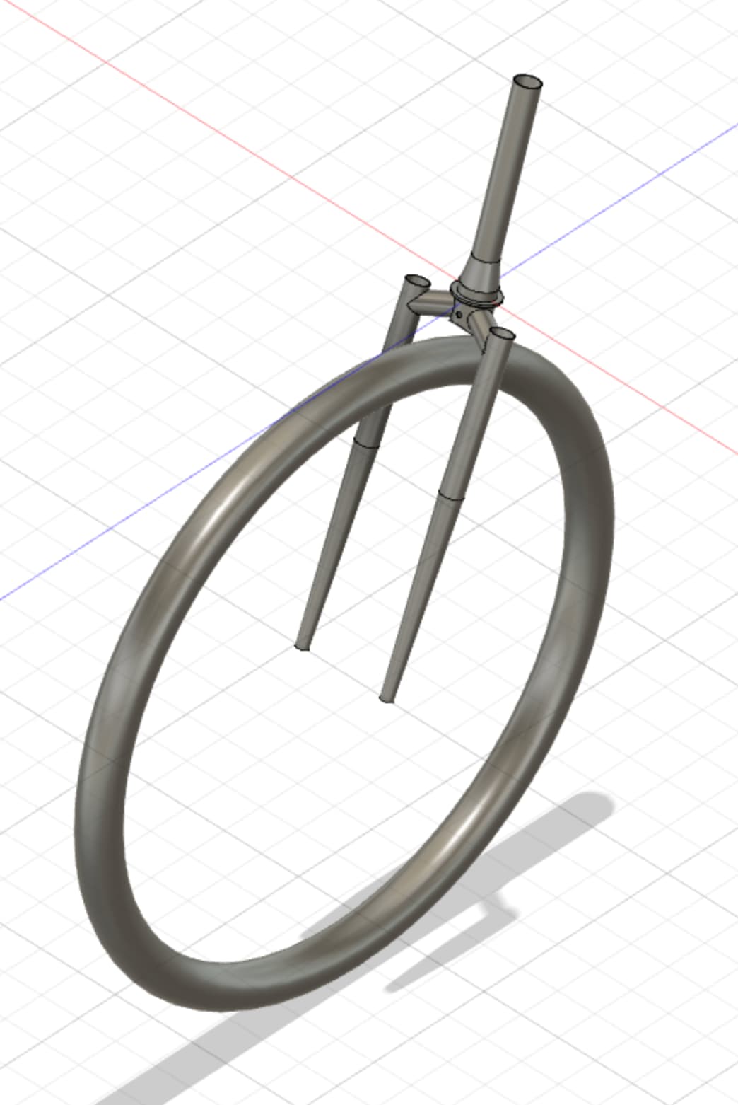
@manzanitacycles I’d love general compatibility, but really only need it to work for one design right now. Trying to make a low-trail segmented fork a la the Endpoint Search Light.
@liberationfab the thru bolt mount looks quite a bit shorter, which would be advantageous for printing. If you just cranked the wall thickness of that part to >1.5mm the part would be really stiff, much stiffer than the tube it is replacing, even with the holes cut out. However stiff does not necessarily mean strong, and I am more concerned with print defects and fatigue failures.
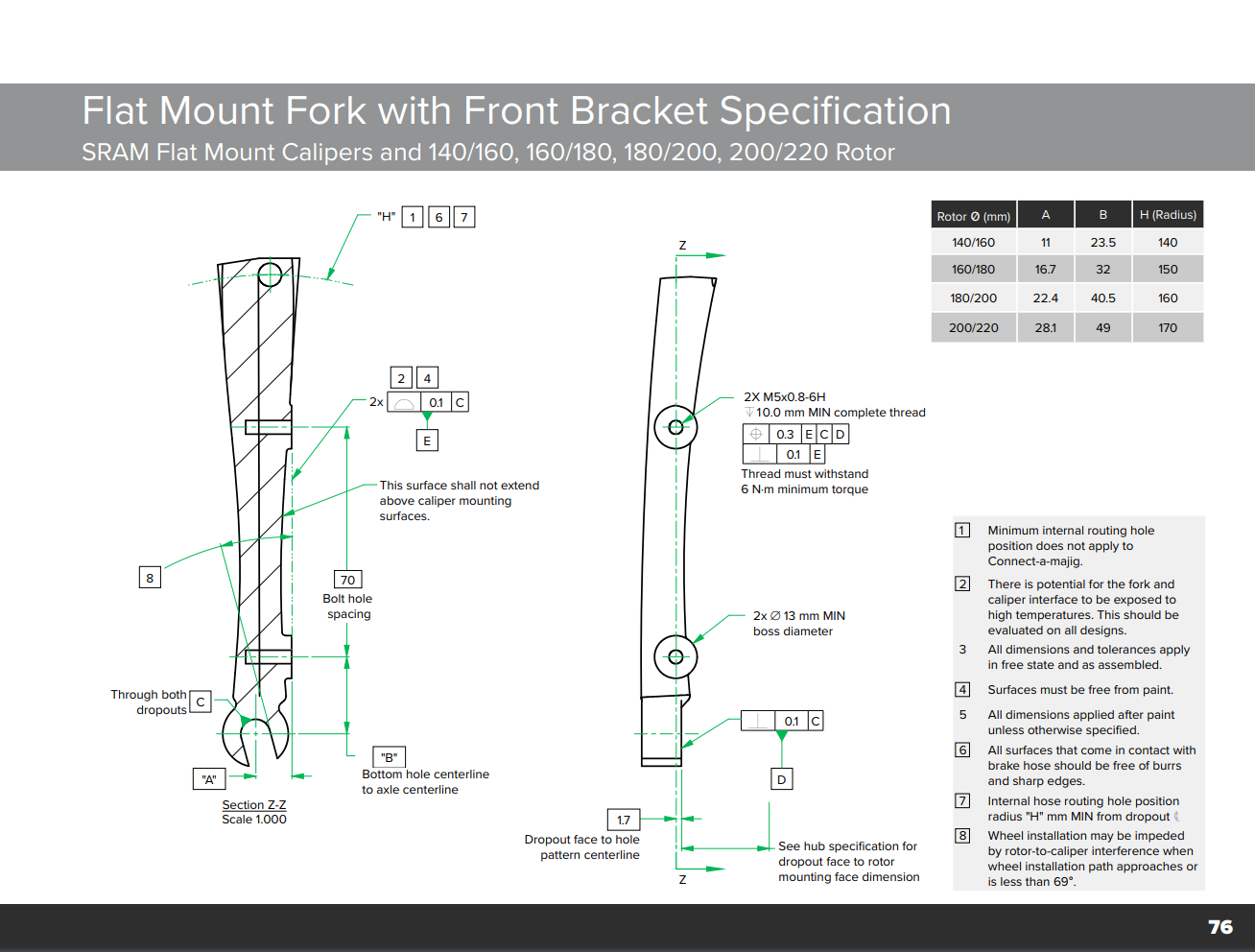
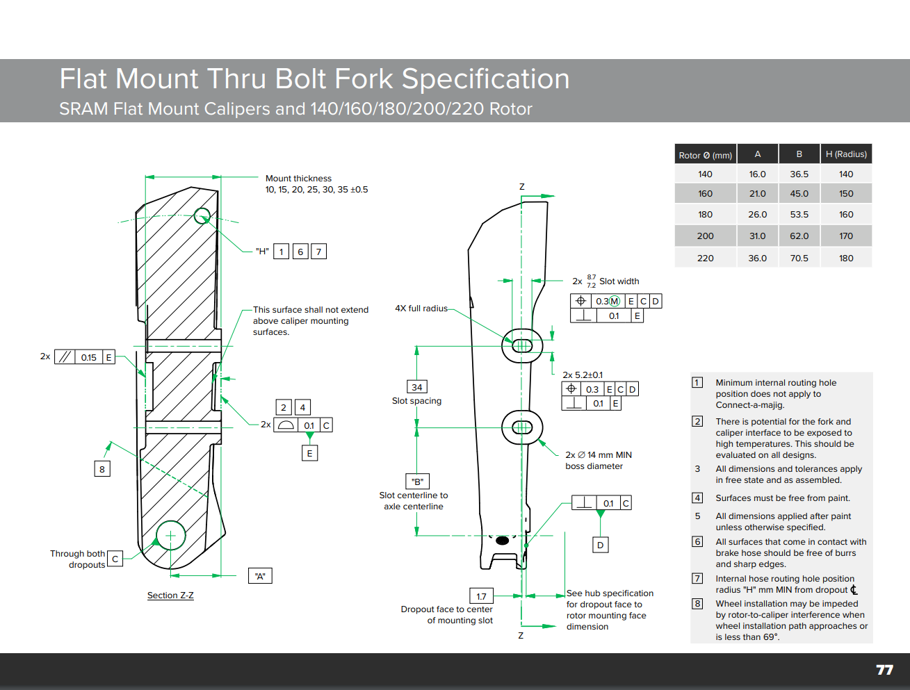
To key everyone else into the discussion, here are the official flatmount specs:
Eva-
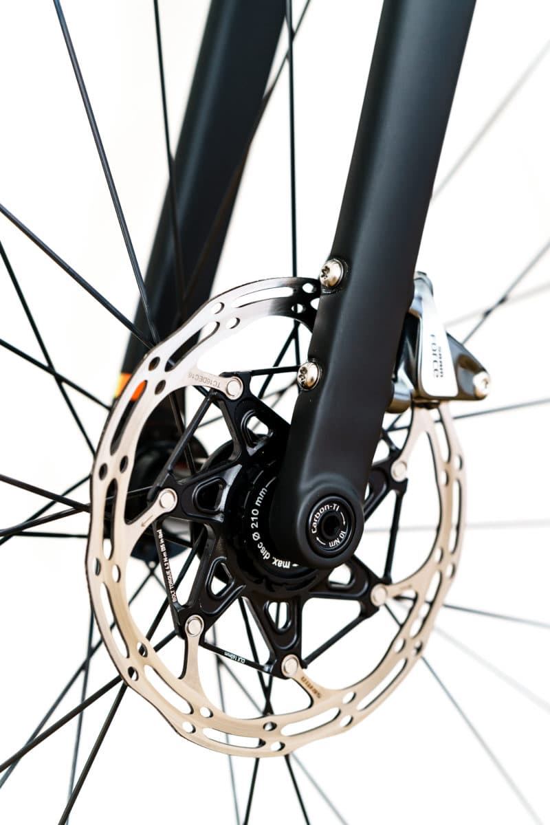
It’s nice to be able to go 180/160 for front rortors. The carbon fork designs get away with using the rear bosses because they have a huge clunky shape they can bury the bosses into.
With steel tubing you are trying to land on a smaller diameter.
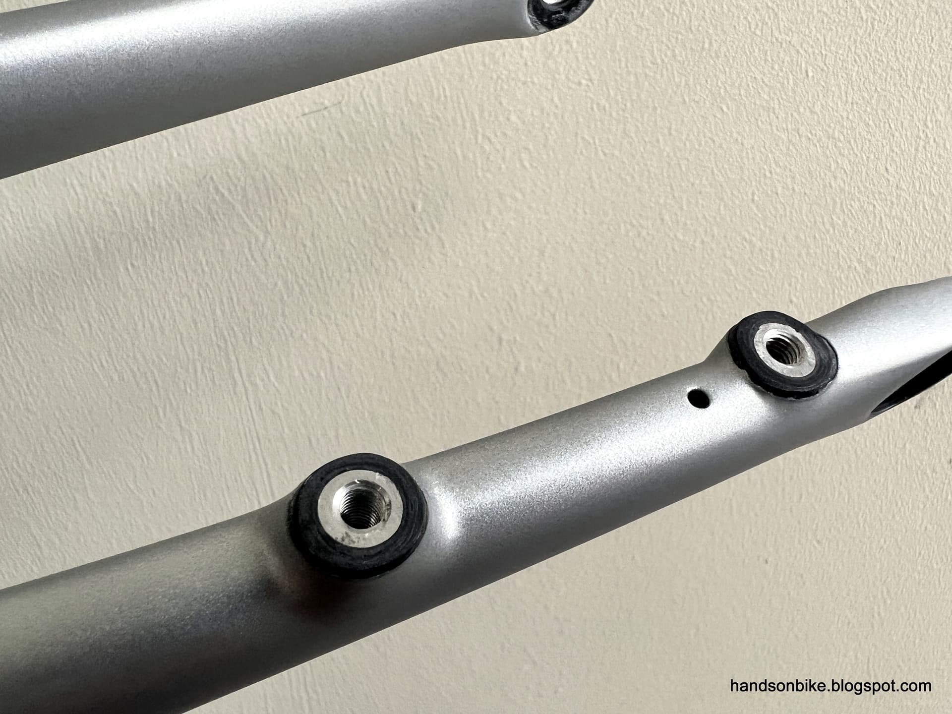
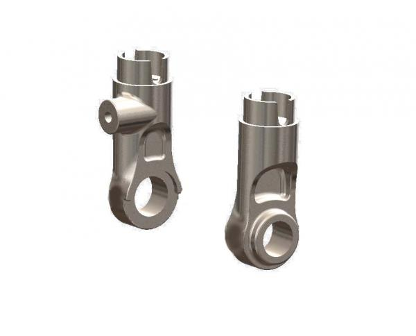
Allotec has a drop out that is pretty smart, if not the prettiest:
what their website hides away in an othe rsection is this part:
which is the matching upper boss.
It’s an ideal candidate for 3d printing as a parametric object. Then you just have to drill a round hole in your fork leg. The boss (or dropout nut as they call it) has a mitered shoulder and enouh threads to avoid stripping, or allow helicoiling later if necessary.
Hahn Rossman
The D34+E54 combo is definitely a slick alternative! And maybe it’s ultimately the way to go. Like @Daniel_Y mentioned, print defects in a fork are a recipe for catastrophic failure. I’d love a super slick solution but realistically don’t have the resources to do much in terms of FAI, FA, FEA, or any other quality-inspiring acronym.
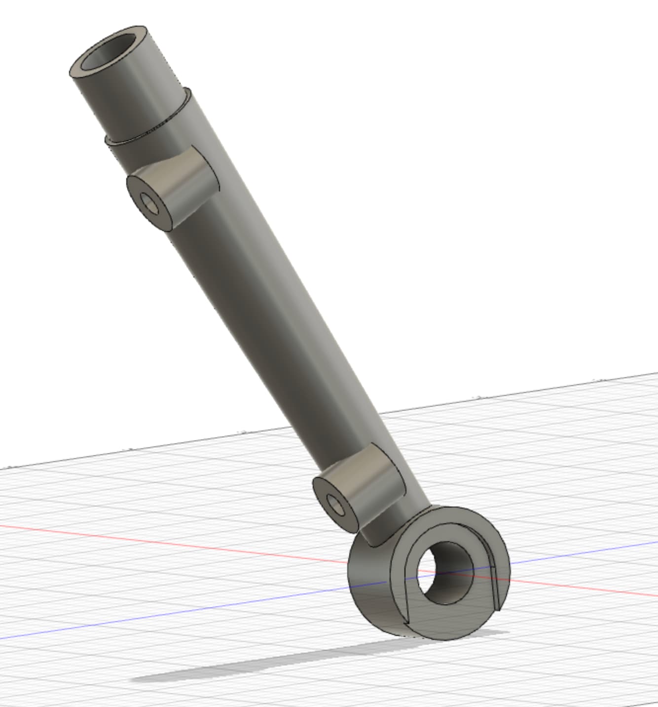
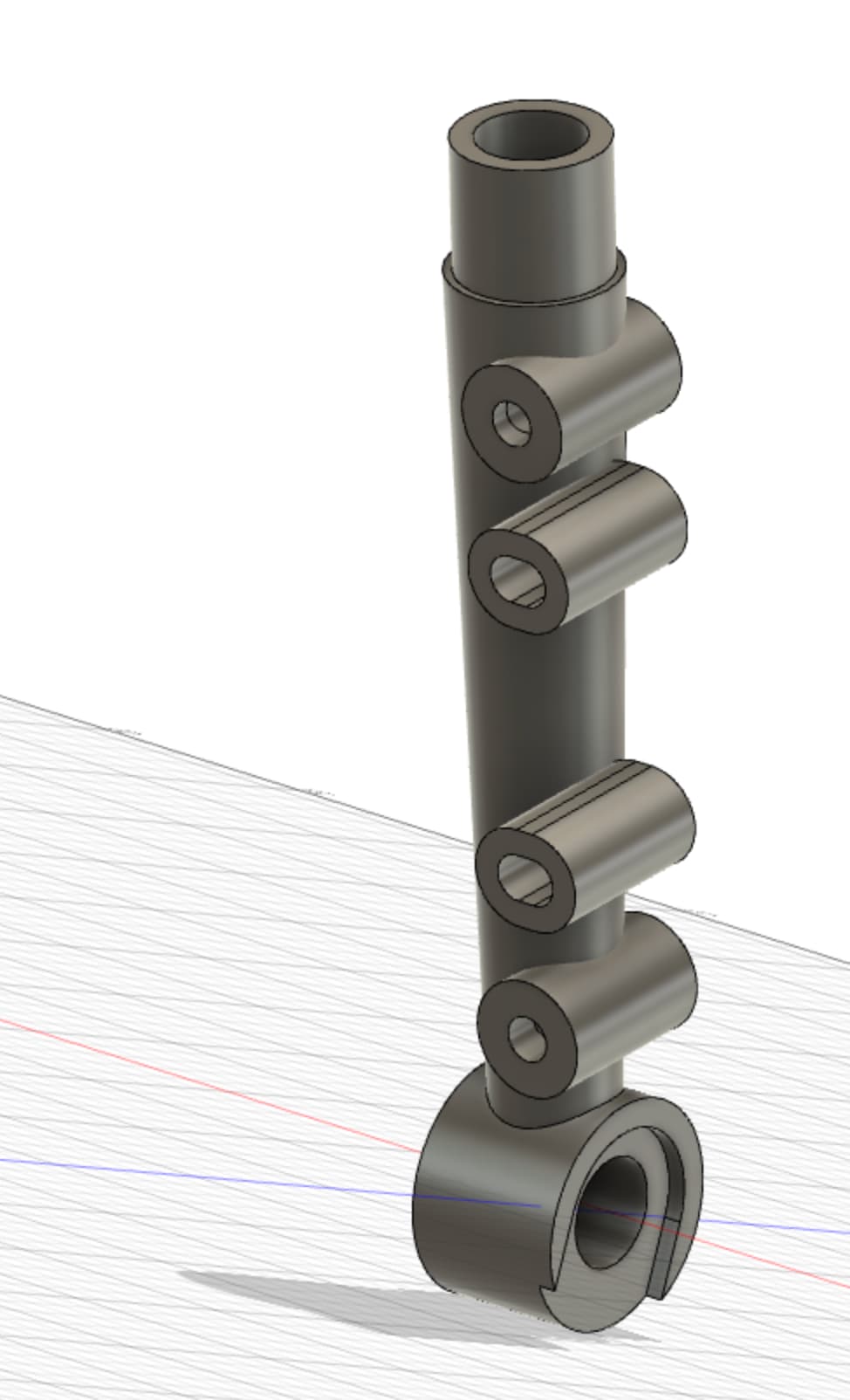
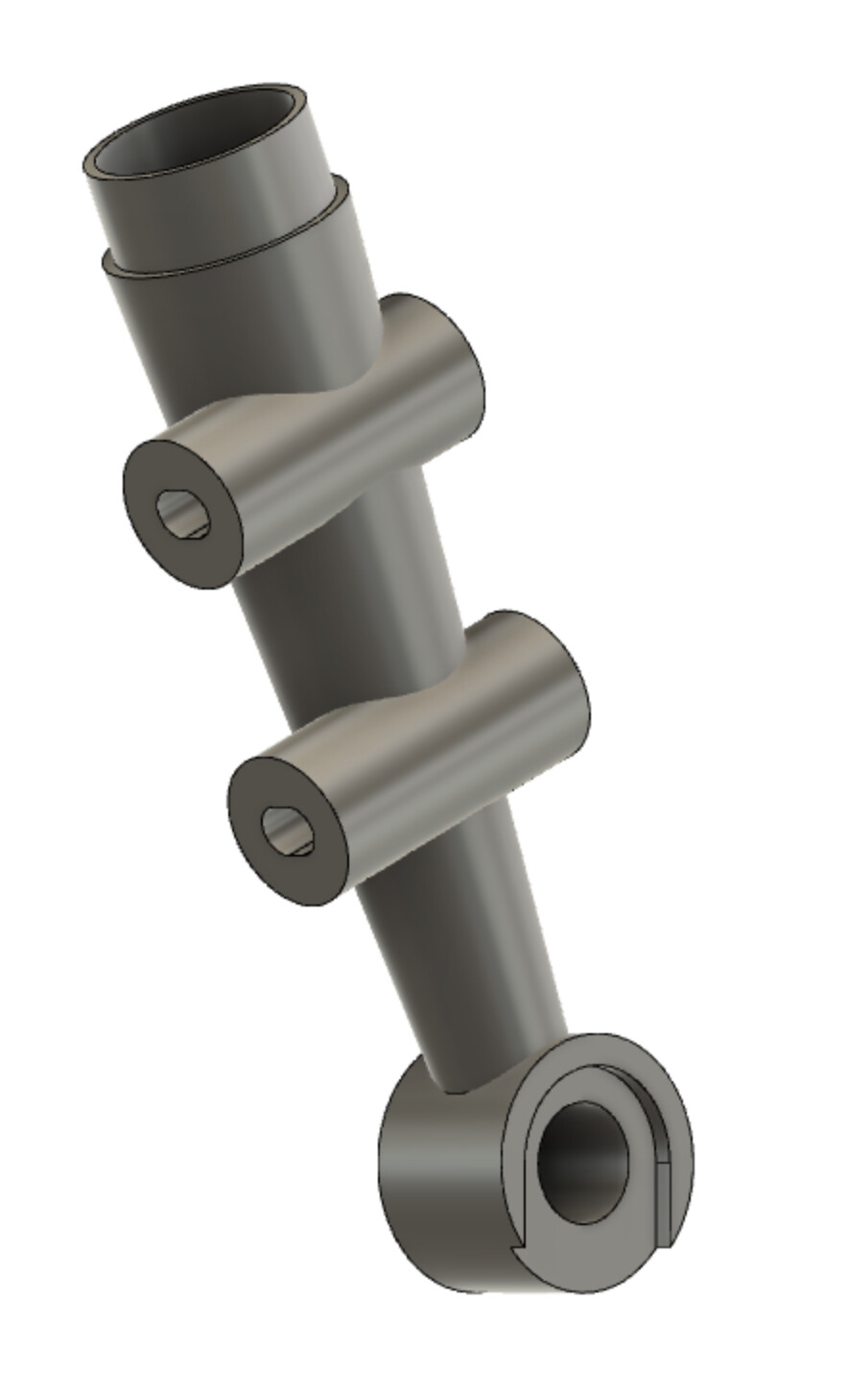
This would be a thru-bolt style 160mm “native” mount. It ends up looking pretty ungainly. The big advantage would be that you could use a straight-gauge Ø25.4mm x 1.2mm tube for the remainder of the fork leg. I might see how rotating the axis of the flat mount face looks like, the 21mm offset is brutal.
I don’t love having a tall dropout like that. I’m not a mechanical engineer but someone here probably is. What are we doing to the fork strength if we put a sleeved butt joint so far up the fork blade?
The one that Hahn linked to seems like a more elegant solution without having to cut the blade.
Is there a good reason to use flat mount on the fork? I sort of get it in the rear for designs that put the caliper inside the rear triangle, but I don’t see an advantage on the front of the bike (vs post mount).
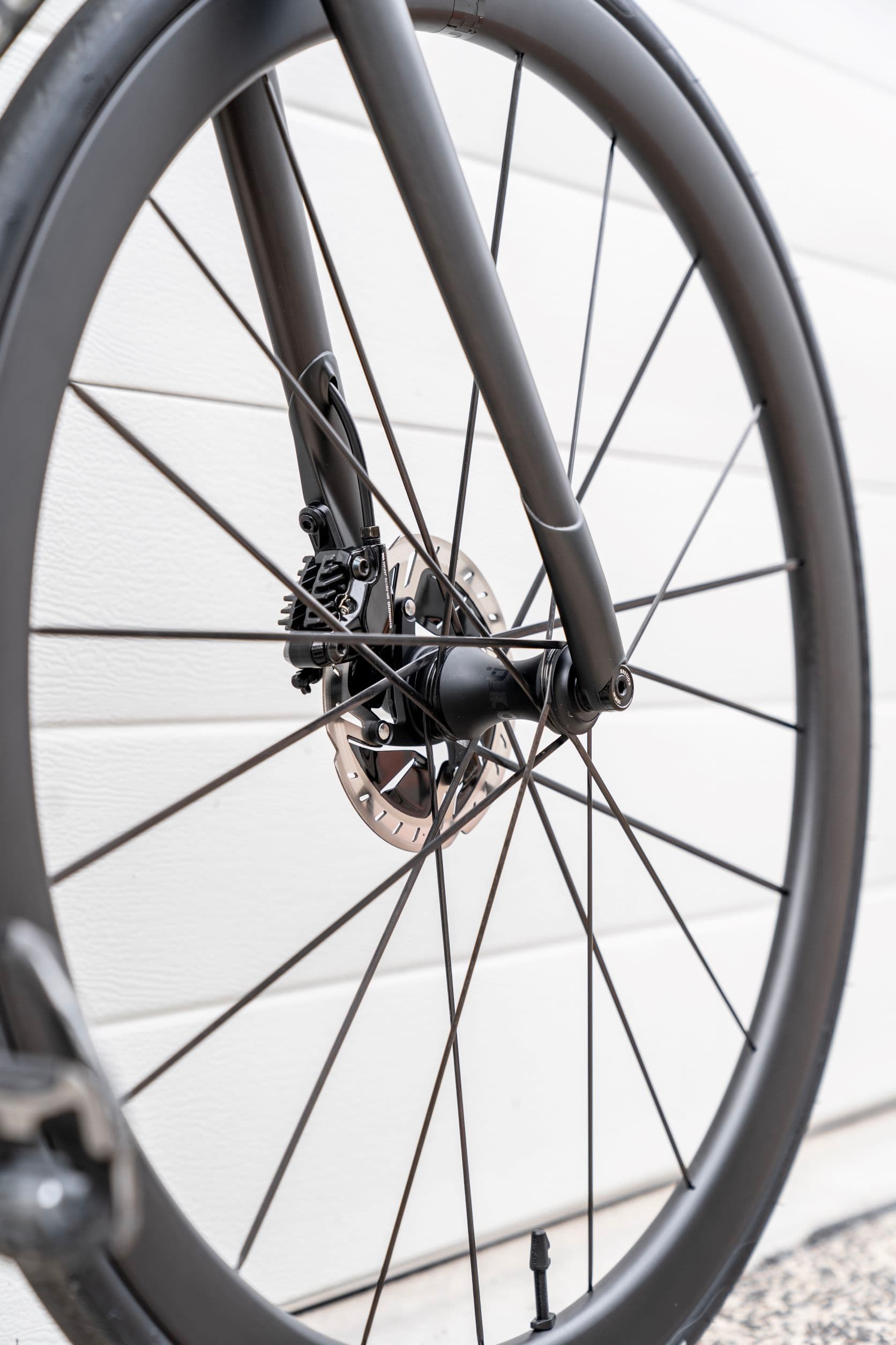
How about a socket design, something like what Bastion does? Theirs are 3D printed ti bonded to carbon blades. Interesting that they went with the front standard instead of a direct mount design. I imagine it could be a lot less chunky if going steel on steel. I’m thinking brazing here as the joining method.