Hi folks!
I’m trying to figure out the source of flex in my frame and want to test for torsion and lateral flex. Step 1 of this is hold the head tube down on my welding table. My plan is to hang a weight on the ends and test for deviation angle.
Question for tried and tested methods of doing this: Should I center the head tube between two cones and make a fixture that clamps it tightly and holds it through friction? Should I just use tube blocks and clamp down the top/down tube near the head tube and assume that joint is okay? How do you folks do this?
I wouldn’t use the whole head set tool but you could use the inserts and replace the centre threaded rod with a another one that you could run into so 100X10EA aluminium brackets and calamp together with nuts. Save possibley bending you head set tool rod.
testing is cool, please show us some of your setup and results!
Im interested to ask, is there a reason to fixture the headtube and not the BB?
the bb interface (assuming BSA) is a pretty convenient interface for fixturing, and as it is perpendicular to the plane of a table (if you lie the frame down) the tooling for doing so can usually all be made in a single setup on a lathe (like a frame alignment table/surface with a whipping post) which makes it pretty easy to manufacture.
I use the head tube as my reference as well, though I use stand offs not a fixed head tube holder . which I need to make. The bb shell just rests on a stand off as well and my measurements are taken off the top of the seat tube and the rear drop outs.
I think the thing that is going to mess up your results is applying realistic loading. Bicycles are indeterminate structures and there isn’t a resource I’ve seen with realistic loading numbers. Everything I know of is inside big companies behind closed doors.
You might find some flexy part of the frame that you determine to be root cause of the bike feeling “flexy” but it might not actually be loaded in the way you think during real world use.
could you instrument a bike? Either using a few string potentiometers, or by gluing on strain gauges into Wheatstone bridges? It might give you the answers you want more directly by showing something that can be turned into actual deflections.
I did an attempt at validation of FEA results once. This was a much more defined question than you have, so the testing was much simpler. Nevertheless the links are as below.
I have this - it doesn’t work since with big torque the tube will spin on the supports. Does it work for you or do you use something under the BB / top tube to block the turning moment?
I have something like he does - his isn’t designed to prevent the tube from spinning - the metal stop on the frame does that for him. He is just using it as a tube holder.
Mine is custom bike (mostly a moped) that lacks a threaded bottom bracket since no pedals. Also I’m trying to simulate frame flex and the flex probably happens in the front triangle. Using the BB to clamp down will artificially stiffen the frame (I think).
I agree - I see what you are saying. Like of course even a motorcycle will flex at 10000N but whats a good number to agree on for my use case where I decide what flex is?
I’m building a v2 frame and I’m trying to get a baseline number down with my test - since I KNOW this current frame sucks and is too flexy. You can send visible waves down the length of the frame just by shaking the front wheel (its a long tail cargo bike). This is mostly to establish a number for myself that I will hopefully reduce with v2. With the hope that reducing lateral flex will fix my frame wiggling when loaded up.
My assumption is that if I execute this test I’ll see crazy flex numbers by any standard (50-100mm deviation at 50lbs of lateral force for example).
I have given this some thought! However I didn’t know they made electronic strain guages! Are these sensitive enough for the tiny deflection we will see with metal frames? String pots are definitely an interesting idea.
Also you just gave me the idea of slapping on a accelerometer when loaded up and figuring out the max lateral force I experience - so I can use that for my test.
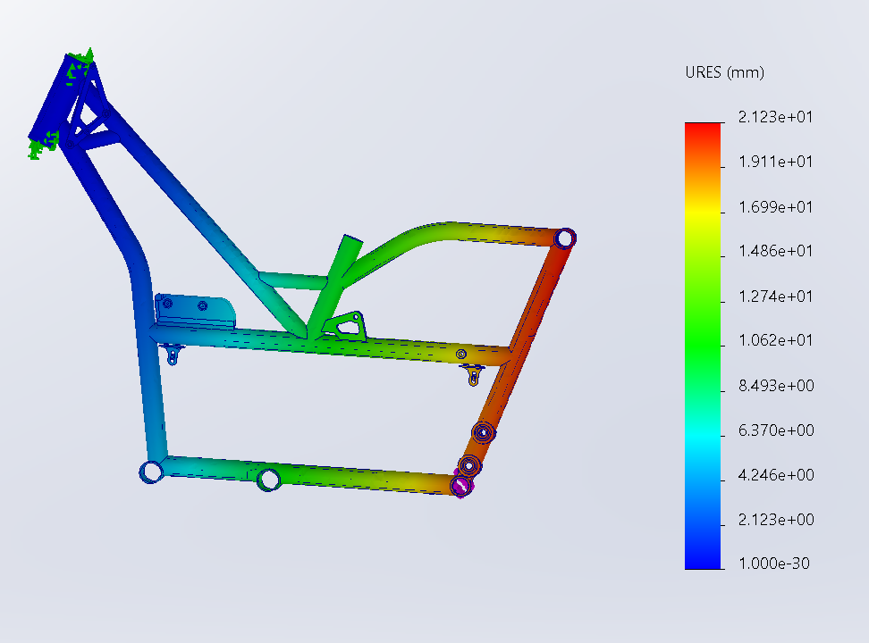
This is what I’m doing. My FEA results did indicate a 21mm deflection at 400N of sideways force - which doesn’t seem too crazy given myself and two big kids at the back of the bike. Do you mostly just rely on FEA for this? If yes how much deflection and how much force do you generally aim for?
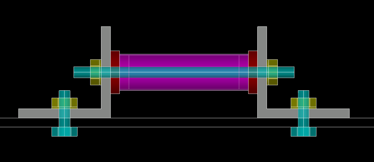
Frame looks weird since its a moped. Fixed geo at the head tube, sideways force exerted through the subframe mounts you see at the back (where a rear rack is bolted on to)
If you REALLY want to get hold of the head tube and have the tooling, expanding mandrels or arbors are fairly straightforward to make or modify from commercial. You’d probably have to turn the adjustment around to pull a tapered nut into the expanding end from a screw accessible from the back. Would also give you a robust shaft out each end to clamp to the table with v blocks, or bore out some blocks if that’s somehow not rigid enough.
Thanks yes I’ve been told this - seems like it’ll have to be custom made since existing ones are all designed for lathes/mills and I coudn’t find anything big enough to grab a 44MM headtube. Will look this up!
might it be easier to hold the rear of the frame and flex from the headtube instead? i don’t see how it would change the results and might be easier to fixture to your table
I agree - I see what you are saying. Like of course even a motorcycle will flex at 10000N but whats a good number to agree on for my use case where I decide what flex is?
In answer to the original question:
So I’m pretty sure any results you get will be scalable. The deflections will be linear with respect to the applied force. I.e If you double the force you double the deflection. So you don’t need to worry about the value used, asking as it gives enough deflection that you an reliably measure it and it’s a magnitude larger than the measurement error in your measuring equipment.
The problem is knowing the directions of the force and in what locations to apply. Bicycles are a mess of combined loading - there’s a lot going on. The results will also be dependent on the boundary conditions - by that I mean which parts of the frame are supported and in what condition (which degrees of freedom are locked? And how are they locked. sliding contact, rigid etc.)
Now that I see the image of what you’re doing:
I think you might be overthinking it. If you’re looking at a single load and a single fixture holding it then can you not just look at the flexural stiffness of each individual tube and bump them ALL up by a known amount? The flexural stiffness is your E x I. So that’s Young’s modulus of the material multiplied by the second moment of area. Do that for the current tube specs then figure out how much stiffer you want it to be then plug in the numbers for alternative tubes until you get a result X times the original and then go with that.
The FEA and testing you’re doing is too oversimplified to really get at the meat of the original question.
I don’t use that alignment check setup to do any cold setting. It’s purely for checking the points againsta the table. I generally don’t need to cold set my front triangles and usually it’s just a tweak of the rear spacing.easily done clamping the bottom bracket in teh vice and just leaning on it with regular checks. I haven’t had to cold set a front triangle for a while now.
.but going back to measuring frame stiffness. I designed a jig that Ride Cycling Review used many years ago. Early 2000’s I had that set up so that the fork and rear drop outs were held and those brackets were able to swivel. The reason being is that the frame flexes as a whole package and things like rear axle and heat tubes etc. don’t maintain their centerlines when the bike is loaded. They place a weight on the horizontal crank and measured defelction to try and quanitfy the review data. The jig they built didn’t have swivelling contact points so in my mind didn’t accurately demonstrate how the frames would flex naturally.
I’m not aware of anyone using https://www.sheldonbrown.com/rinard/rinard_frametest.html as noted above by JIMG. I know the bike in question is not a road bike, but this is the only readily available, public data that can be used as an empirical comparison. Do not be scared by the fact the data is old, the data contains aluminum, steel, and carbon frames across a really wide range of flexibility and is good enough if you are starting from zero, which we are since flex data is kept secret by the big boys. I crunched the numbers and tossed out a few outliers, and found that the minimum, average, and maximum front triangle flexibility was 3.6, 9.9, 15-mm. The minimum, average, and maximum rear triangle flexibility was 2.5, 4.3, and 6.1-mm. Also, don’t be consumed by the idea that there is a perfect way to measure frame flex. Just mount it like Rinard did, weight it down, see how it compares.
Thanks! Yes I’ve switched to using this and using the swingarm pivot as a alternative mounting location for the lateral flex test. Ive since found out that motorcycles are teste this way!
Thats some next level stuff. Makes sense. How did you make them swivel like that without flexing themselves? super tight bearing fits?