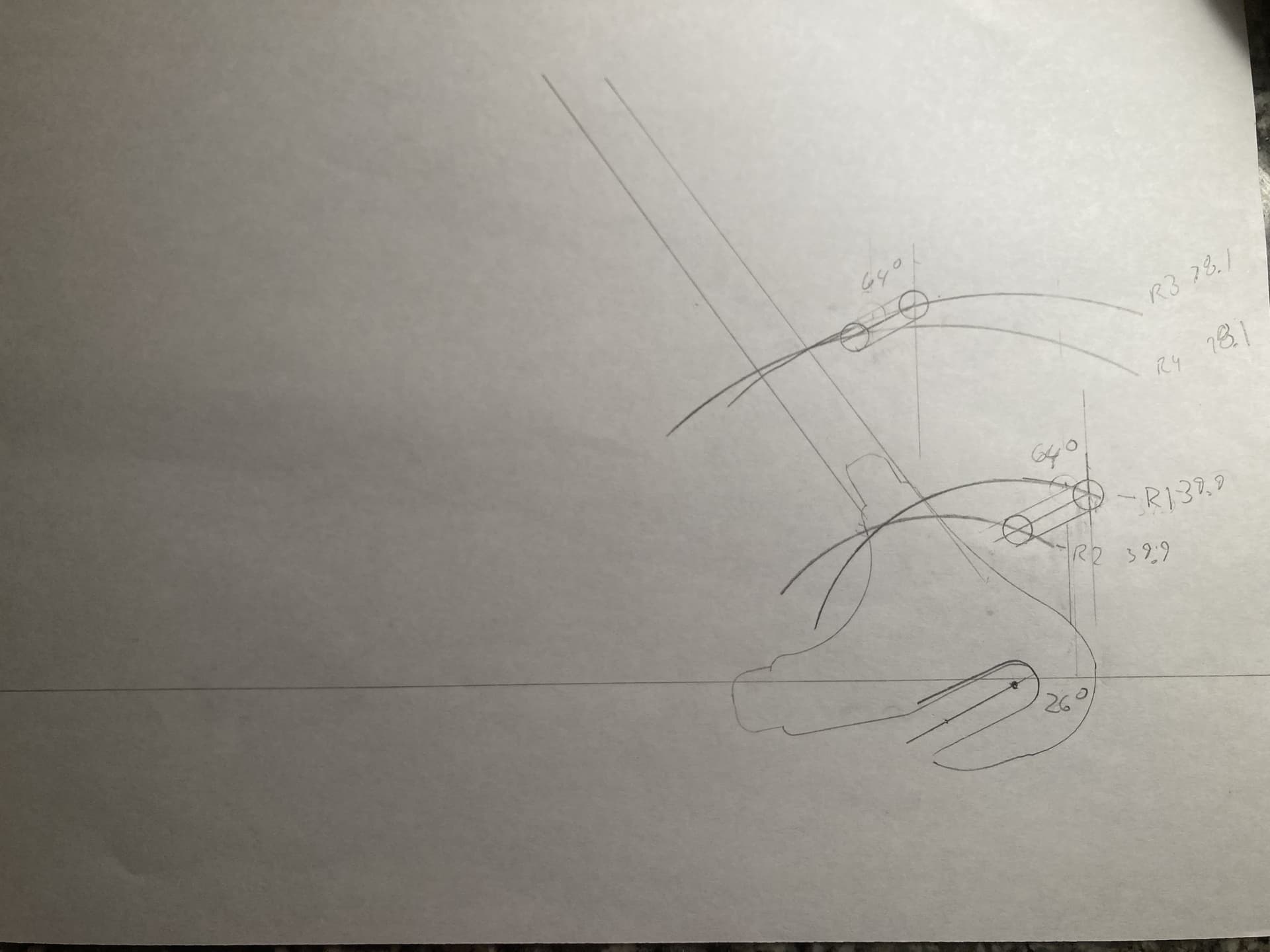
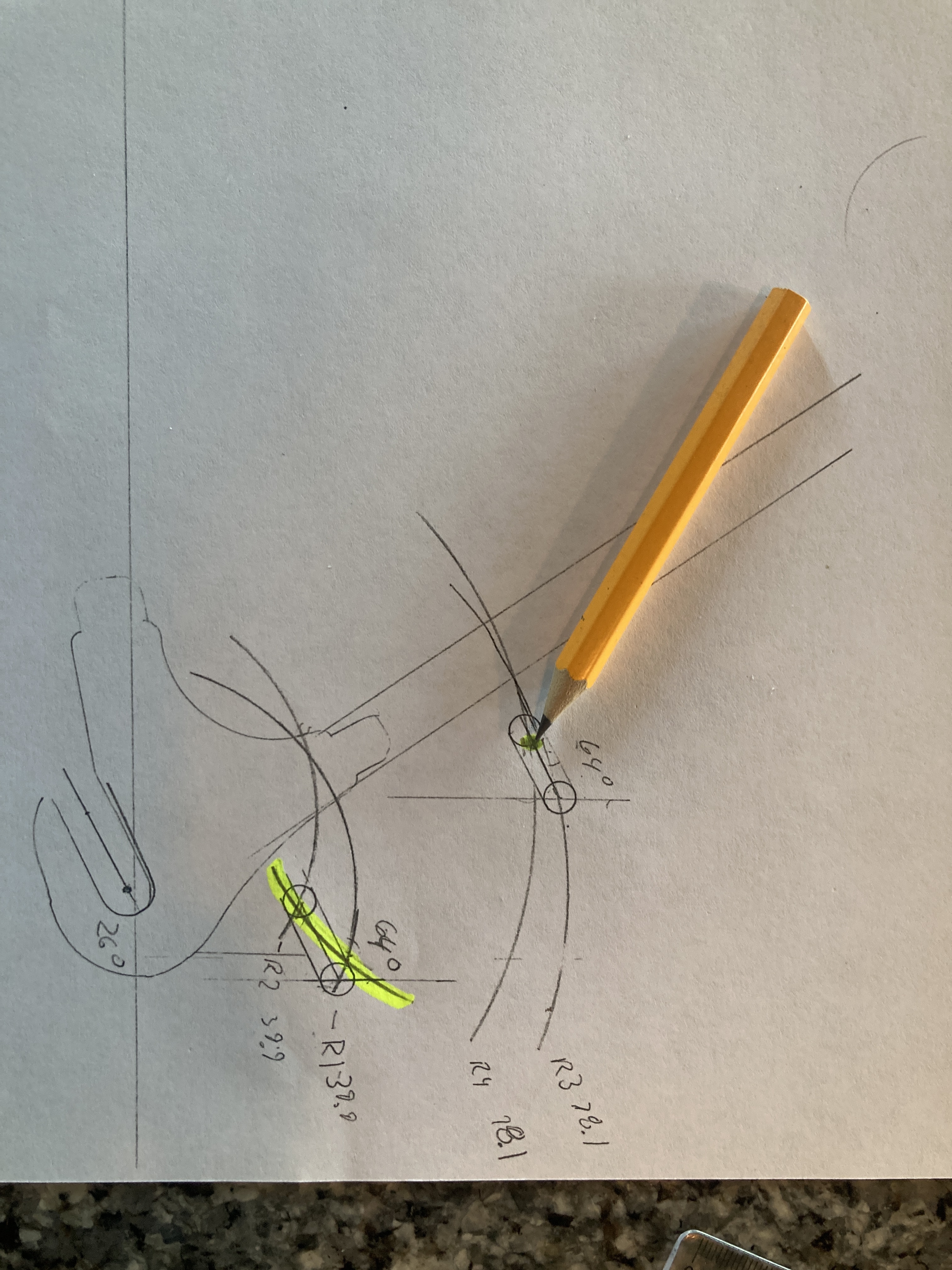
I apologize for the crude drawing but I want to understand the concept before spending days attempting to model
I am building a frame with semi horizontal dropouts and I cannot find anyone that sells a slotted ISO tab so I am trying to design one.
Radius 1 and 3 represent the hole locations at the rear axle location of the drop.
Radius 2 and 4 are drawn off the front axle location of the drop.
The drop is at 26 degree angle from horizontal.
Am I correct that if I connect the radii of each location at a 26 degree angle (64 off vertical) that will match the sweep of the brake as the wheel is positioned in the drop out?
Any input is appreciated! I hope this makes some sense…
Thanks! I am just making the tab, I already have the dropouts I want to use.
I am debating on modeling them and having them cut or just doing it by hand. I don’t have a mill but I’ve been known to get crafty with a drill press and files
My main concern is a memory of surly dropouts/tab where the upper bolt hole had almost no adjustment and the lower was concentric(?). I do not understand how that achieved the proper adjustment.
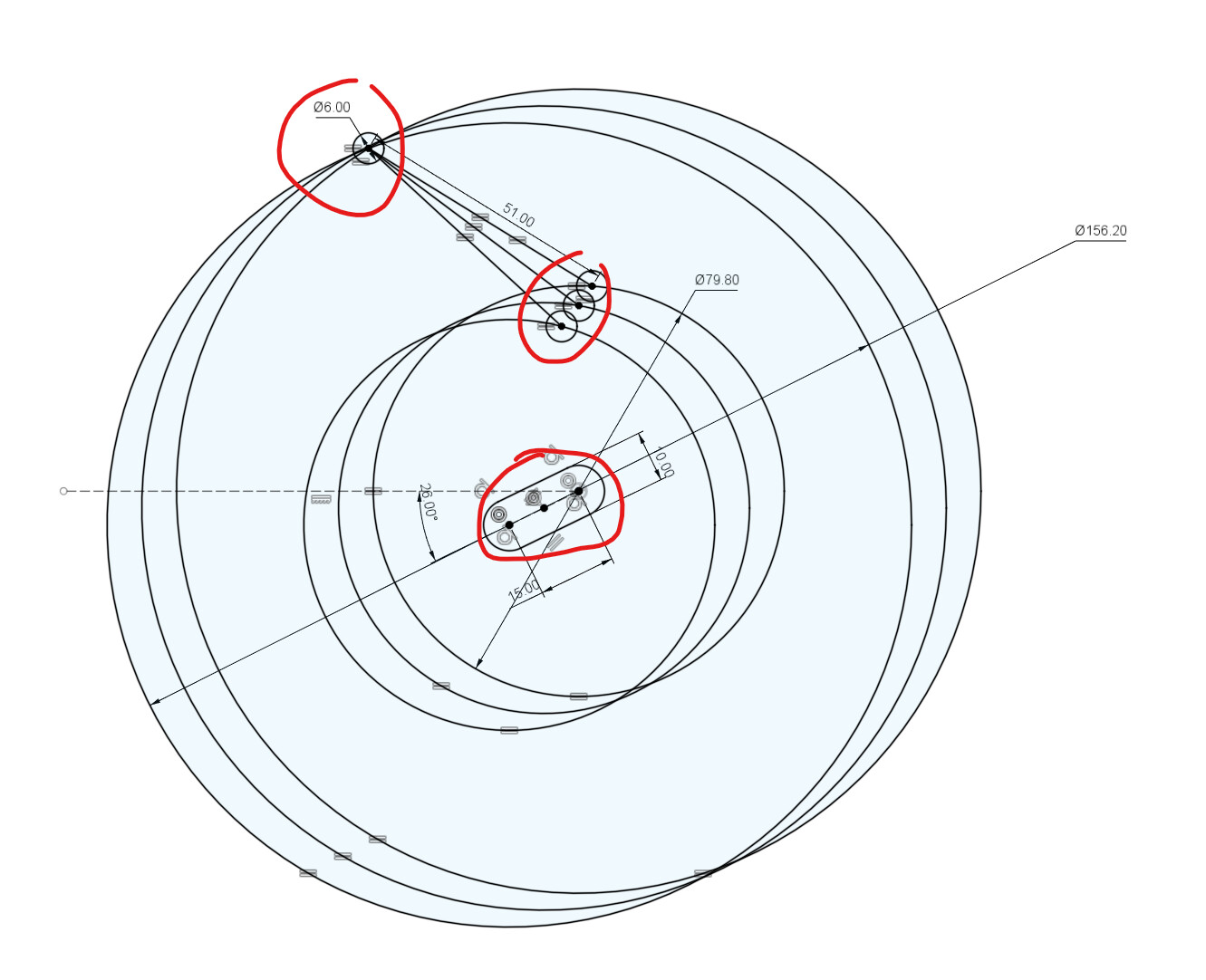
I used this drawing to make by brake tab tool and to design this tab.
This was just scratch work, so please double check it. Assuming the drawing checks out, my concern would be the top bolt hole interfering with the SS. It would depend on your dropout design and SS-CS angle
Regarding cutting out vs laser cut:
Im obvisouly a bit biased towards 3D CAD and laser cutting. I think you can look at it this way: you already know you can hand make the tab. This could be a good project to try and learn something new. Brake tabs are probably the lowest barrier to entry for CAD and CNC workflows.
Or a hybrid approach: CAD the design, print it out 1:1, make it by hand
That is very interesting. Your drawing helped a lot. I cannot use the intersection of R3 and R4 due to the seat stay.
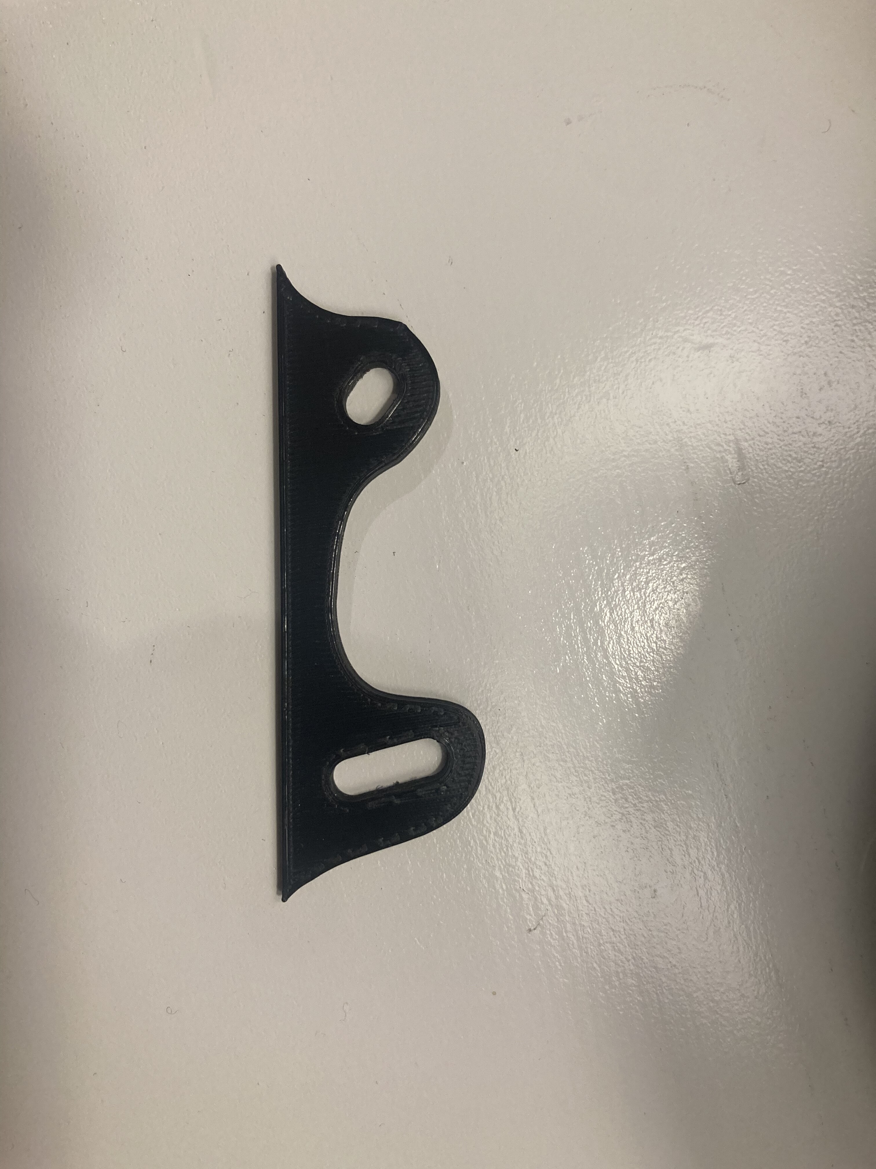
I attempted to use a point on the line that connects the holes of R3 and R4 and drew a radius of 51mm (hole spacing). I believe the top hole will need slotted ~3mm to accommodate for the large radii not intersecting at the bolt. This will be much more visually pleasing than both being slotted 20mm.
Hopefully I can make time to model it in the next couple days.
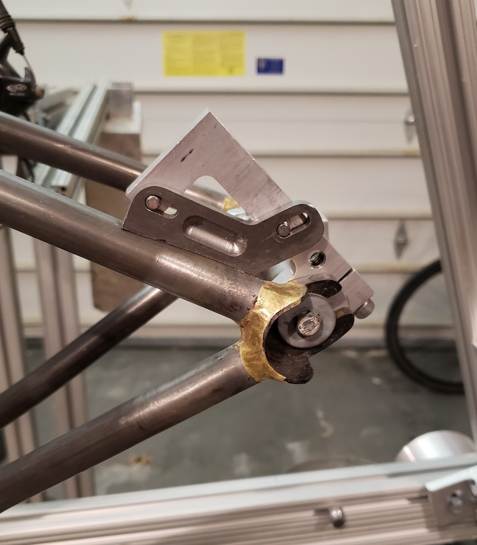
I used 1/4" material and I think it is plenty thick. This was made from McMaster Carr part number 6554K15. If you are in the states it should be less than 20 bucks. I have noticed that getting sections of flat bar seems more economical than sections of plate.
I will have to check out the send cut send option. That also seems pretty cool.
Can you tell me how you decided the angle at your bolt slots? Yours is slightly different due to it being a track end but I think I I can better understand how you got to the angles it might help.
My original design is bulky and ugly your design with the top slot following the seatstay is much better…
Thanks
Yep
I made sketches a lot like yours and Daniel’s and just drew the bolt locations with the axle all the way forward and the top bolt rotated until it was close to the seatstay. Then I drew the bolt locations with the axle all the way backwards and rotated forward up to the seatstay. This gives the location of the ends of each slot.
I wanted the brake as forward as possible so the wheel would come out without having to loosen the brake.
It looks like gschwell also used a similar method.