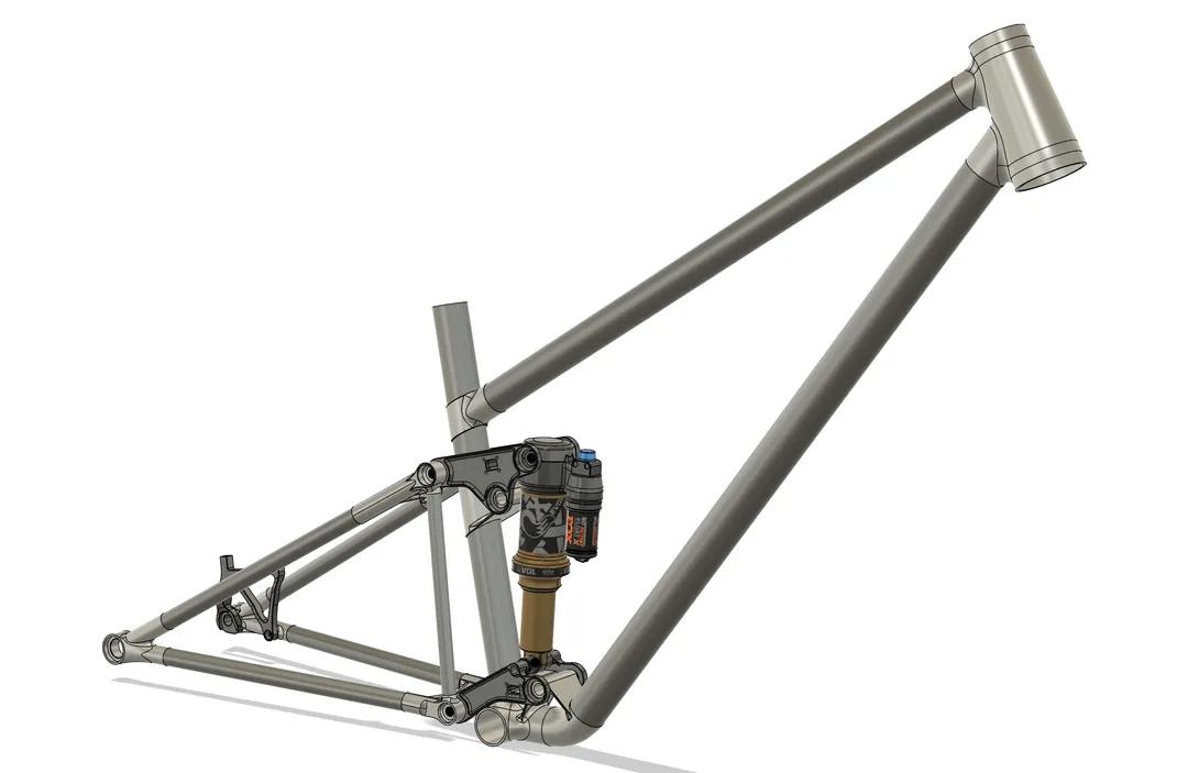
Before you get too far on the 3D modeling,(which is looking great!) It might be a good idea to figure out what you’re doing for hardware. If you are modeling the bike after the Lapierre, can you obtain the original suspension hardware and model your parts after that hardware? Or will you be forced to create custom suspension hardware? If you’re looking at cost savings measures, it might be a good idea.
2 Likes
This is a very cool project. Hope your project goes well. Where are you going to university?
1 Like
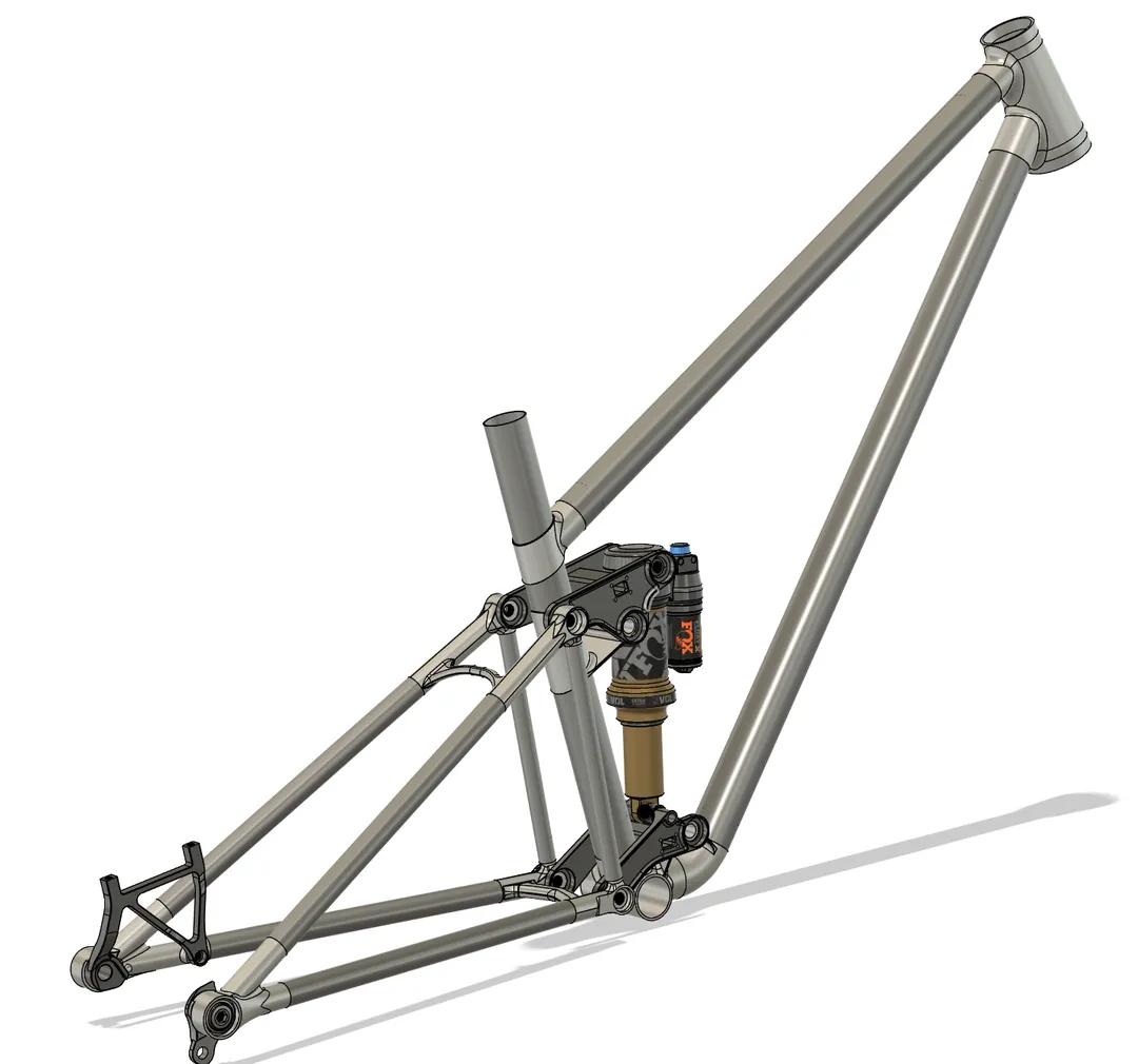
The hardware will be off a Vitus Sommet. There’s a company in the UK doing kits so I’ll get those.
1 Like
Sheffield Hallam. They have a metal printer and Steve Peat’s local trails so it was a no brainer for me.
1 Like
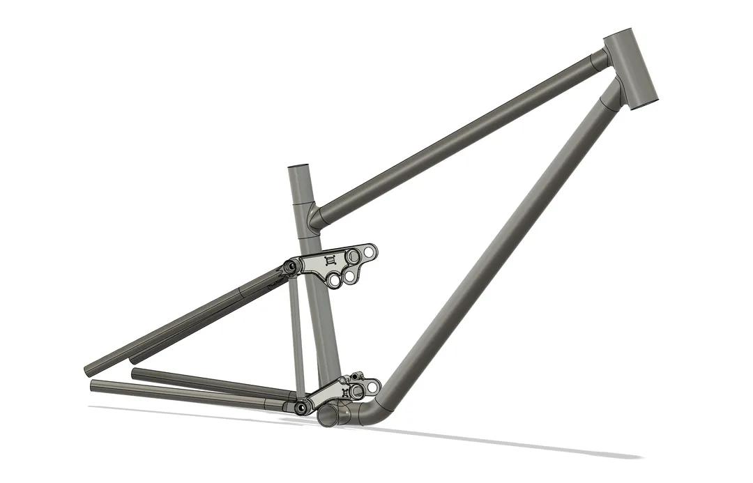
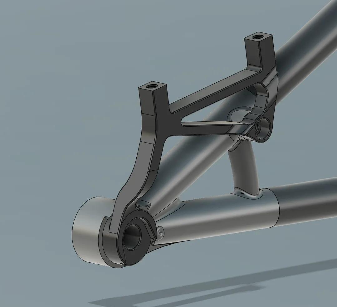
Hehehehehehe I love it! Took me a lot less time to make than I thought and I finally tackled brake mounts! Yippee!

2 Likes
What’s the thinking behind having the mount anchored to the chainstay rather than the seatstay?
The force would be going through to the chainstay anyway via a brace, I just thought I’d cut out the middle man.
1 Like
I see. When the mount is on the seatstay with a brace, the forces are spread over the seatstay and the chainstay. I think your design isn’t really any different from just having the mount on the seatstay with no brace. (I’m making no assumptions about the diameter or wall thickness of the stays, but guessing they are similar.)
2 Likes
Huh, yeah that actually makes sense! I’ll update the design soon!
1 Like
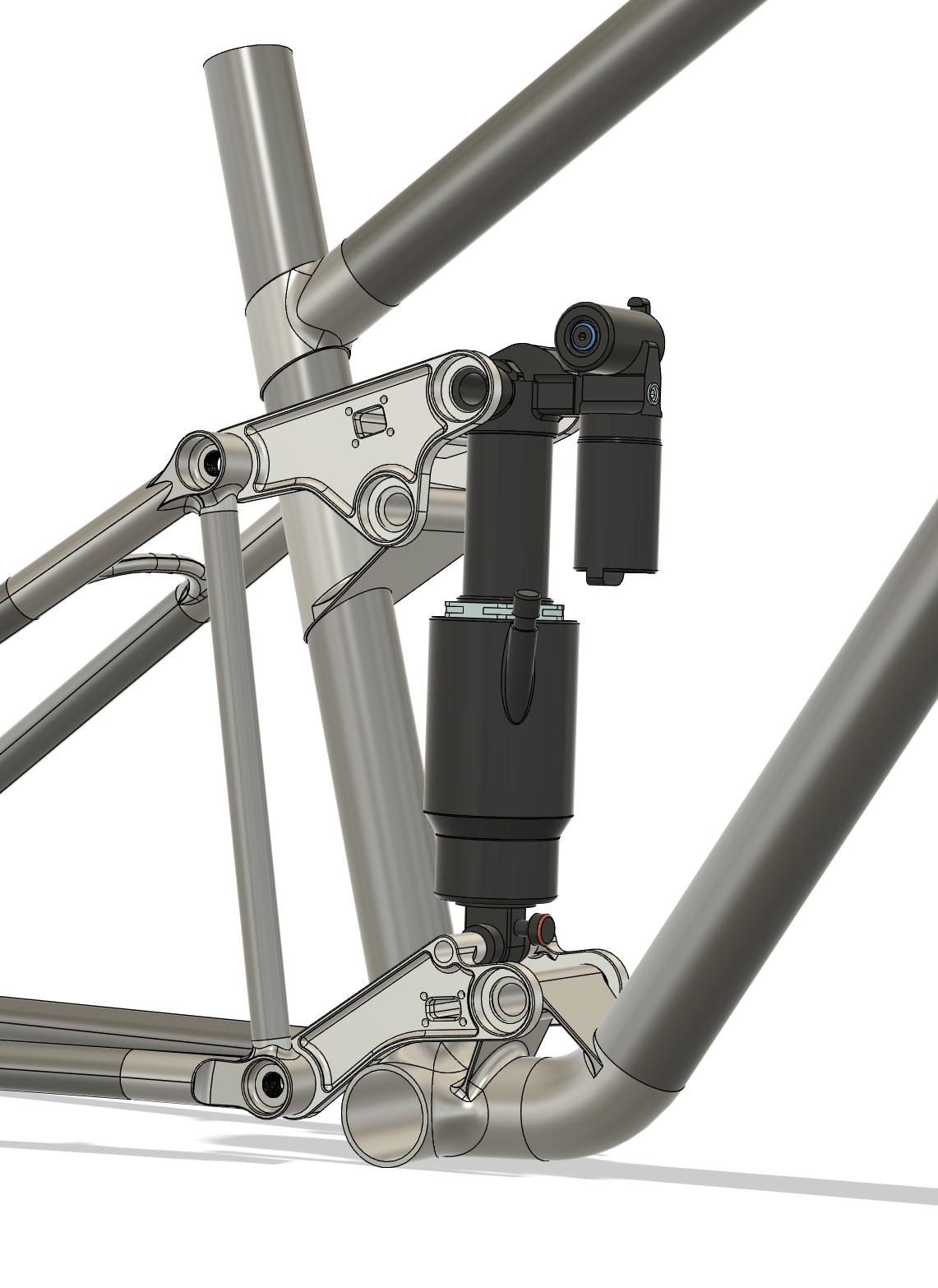
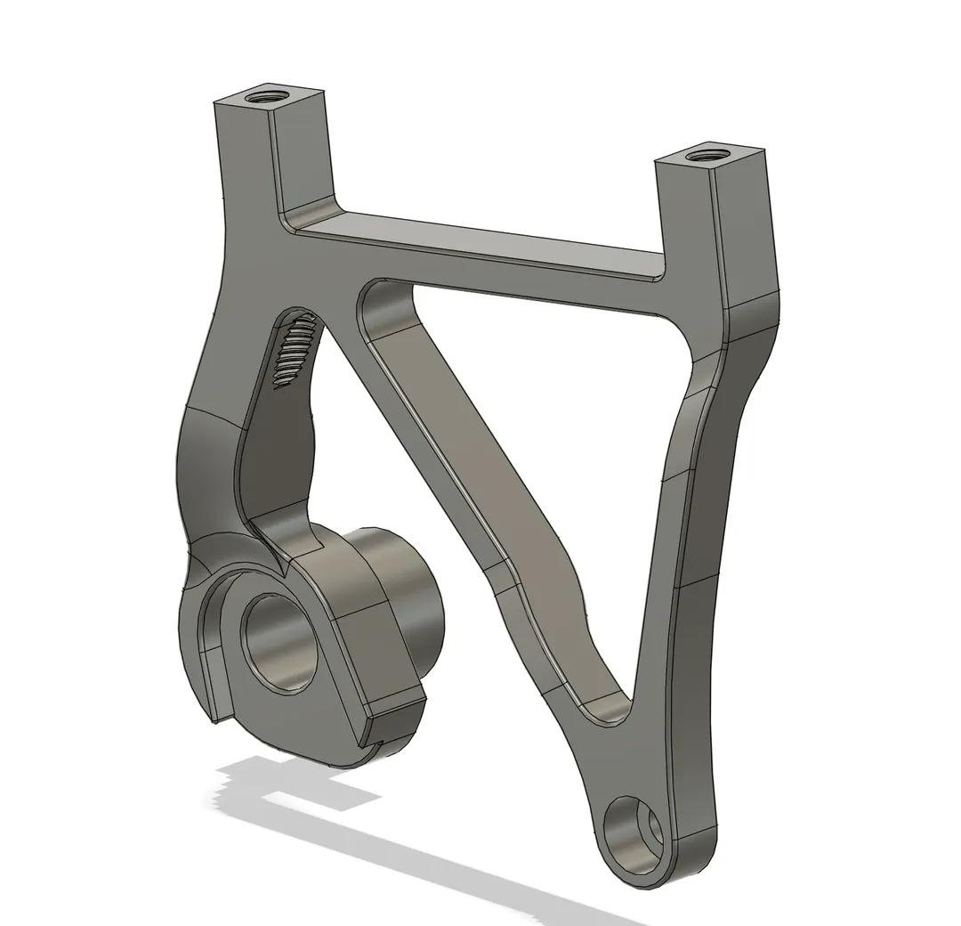
As promised. The mount is smaller and stiffer, should be easily compatible with any bike that has the mount for it. Radial distance for the mounting thread (m6) is 170mm and distance from the inner face (that the axle touches when a wheel is mounted) is 9.1+/- 0.1 mm(The distance from the frame face the brake mount fits on is just that +7.) The frame interface itself is literally just a mirrored UDH because I am lazy.
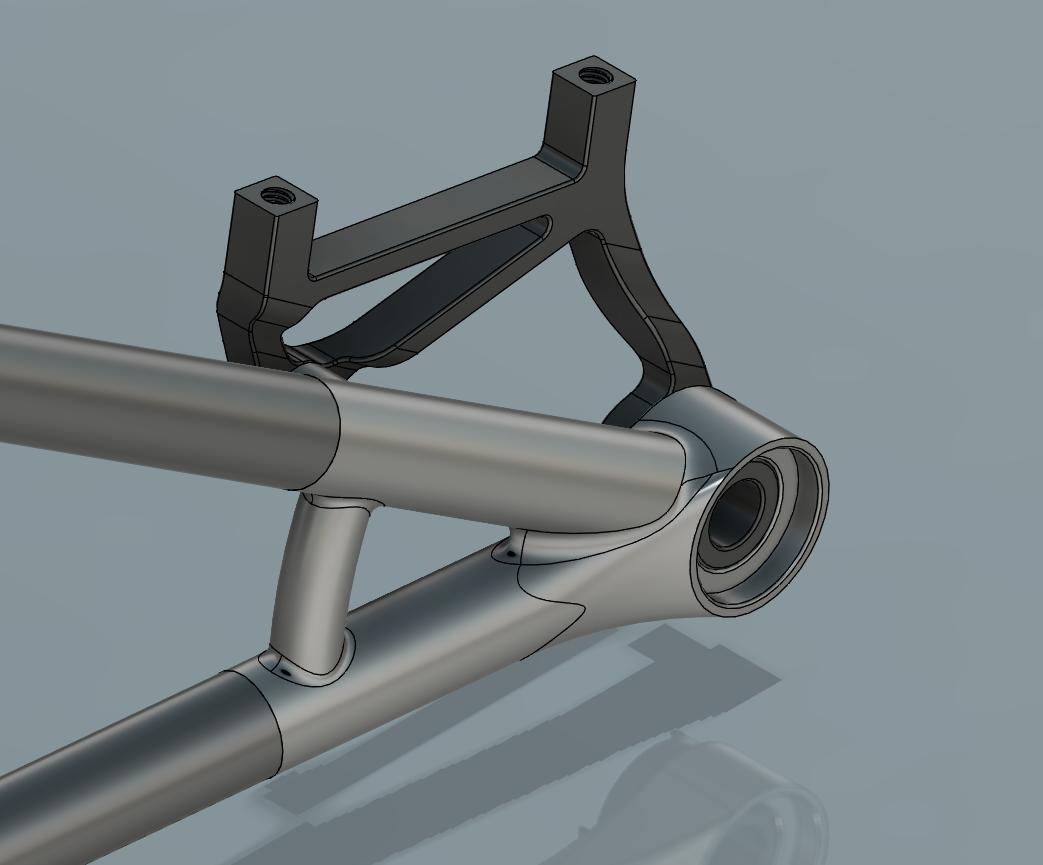
I will be making an attempt to include this brake mount in all my other designs going forward, as I believe it’s important to have as many shared components as possible!
4 Likes
Looks nice! Little CAD tip: define your fillets by chord length on your 3D printed parts instead of by radius, they’ll have a nice and consistent width then ![]()
3 Likes
Could you show me an example of where they differ? I’ve never used chord length before so I have no clue what it looks like ![]()
Of course, here’s a quick comparison:
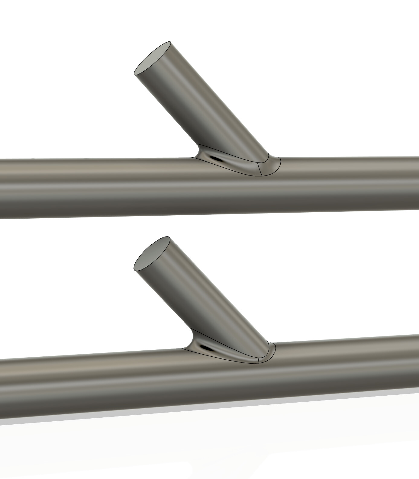
The problem with constant radius fillets is that how big they actually get strongly depends on the angle between the surfaces, which is constantly variable when you’re combining curved surfaces like this.
2 Likes
Oh hell yeah! I’ll definitely be updating to chord length fillets where I can, they look a lot stronger. Thank you!
1 Like
No idea if they’re really any stronger or not, I just know they look nicer ![]()
I guess if you make your chord length fillets to be as wide or almost as wide as the widest part of a standard fillet it would be stronger.
1 Like
strength-wise, the gold standard would be a loft of constant curvature, I don’t know if this is possible in fusion. It’s a shape that is only really possible to manufacture with casting or 3D printing and gets used a lot in topology optimization, where you connect organic looking shapes to geometrically regular shapes. Through its curvature constant nature, it reduces stress risers at abrupt changes in cross section (in theory…)
I’ve quickly slapped something together in Solid Works for you to get an Idea what it looks like:
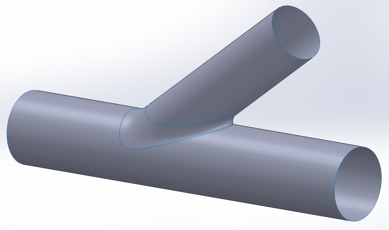
3 Likes
Interesting! Looks like the exact opposite of what the constant radius fillet does, small where the angle is tight and wide where the angle is wide.
So I guess when keeping it simple the chord length fillet is already closer to this than the “regular” fillet so should be stronger? Not quite like the constant curvature but better than the constant radius.
2 Likes
I’ll be moving to solidworks eventually as that’s the software used at my uni of choice. This looks like an exciting tool to have available.