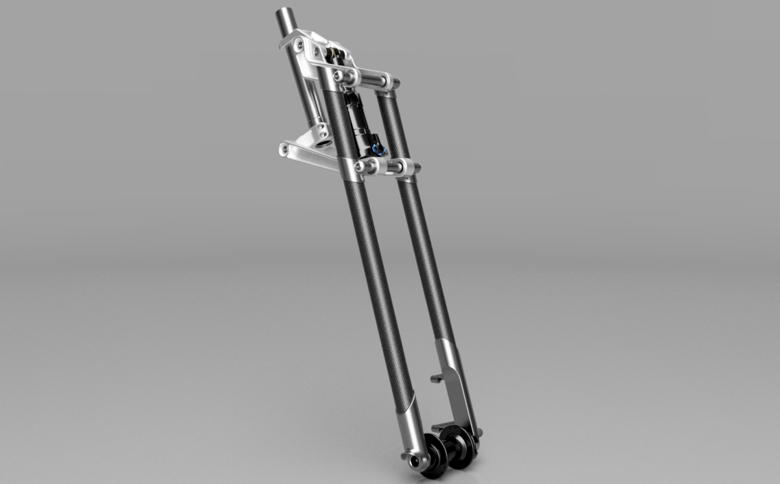
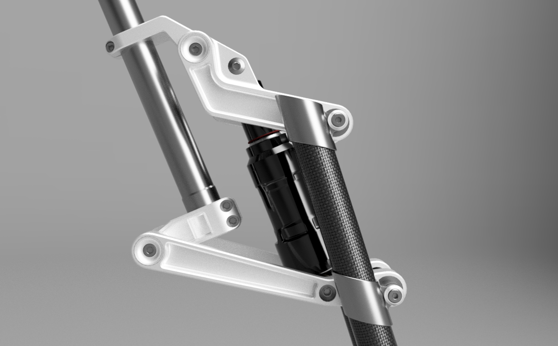
I don’t know why I became obsessed with this idea the last week or two, but it’s probably my ADHD. I’ve always thought it would be cool to revive an old Girvin fork and give it some modern standards such as thru axles and disc brakes with compatibility for 29er tires. I had never really given too much thought because I figured it would be too much money to invest in a simple project. Then after looking at it and seeing all the steel bikes with carbon seat masts/seatposts, I realized that could be a way to make the fork legs. I could fillet braze all the fork leg fittings quite easily and then just bond in the carbon fiber tubes. The other bits and pieces would be machined, but they are relatively small and if you are clever, can be made with minimal machining.
When I worked in a bike shop circa 1993-1994, a Proflex rep stopped by and let us test ride a bike. I only got to fool around in a parking lot, but I really liked it. Now that those bikes are so cheap, I’ve always wanted to pick one up to relive that.
my dad has an old proflex with the girvin fork and the shock with the electric lockout. I always thought it was a pretty good fork. Product of the times for sure, but I’ve always wondered what it could be when viewed through a modern eye. But also limited to the tools that I have available. and even then this would be a stretch to create for me.
Also, @SoyWater you’re too kind. Maybe this winter I’ll take on this as a project.
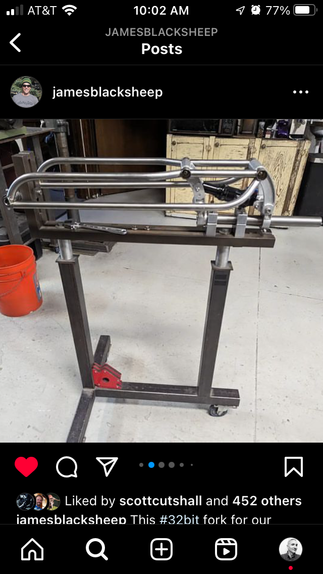
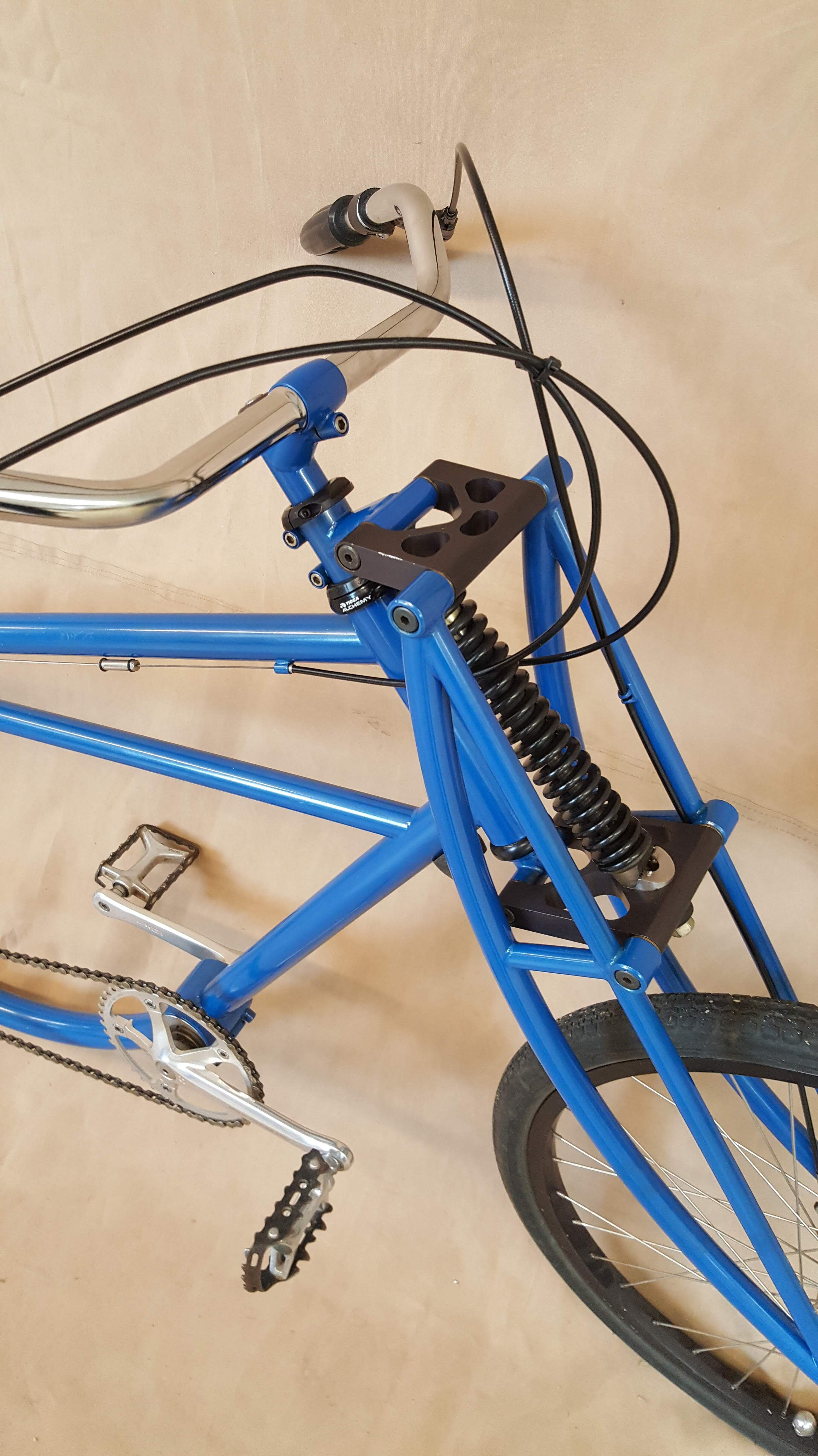
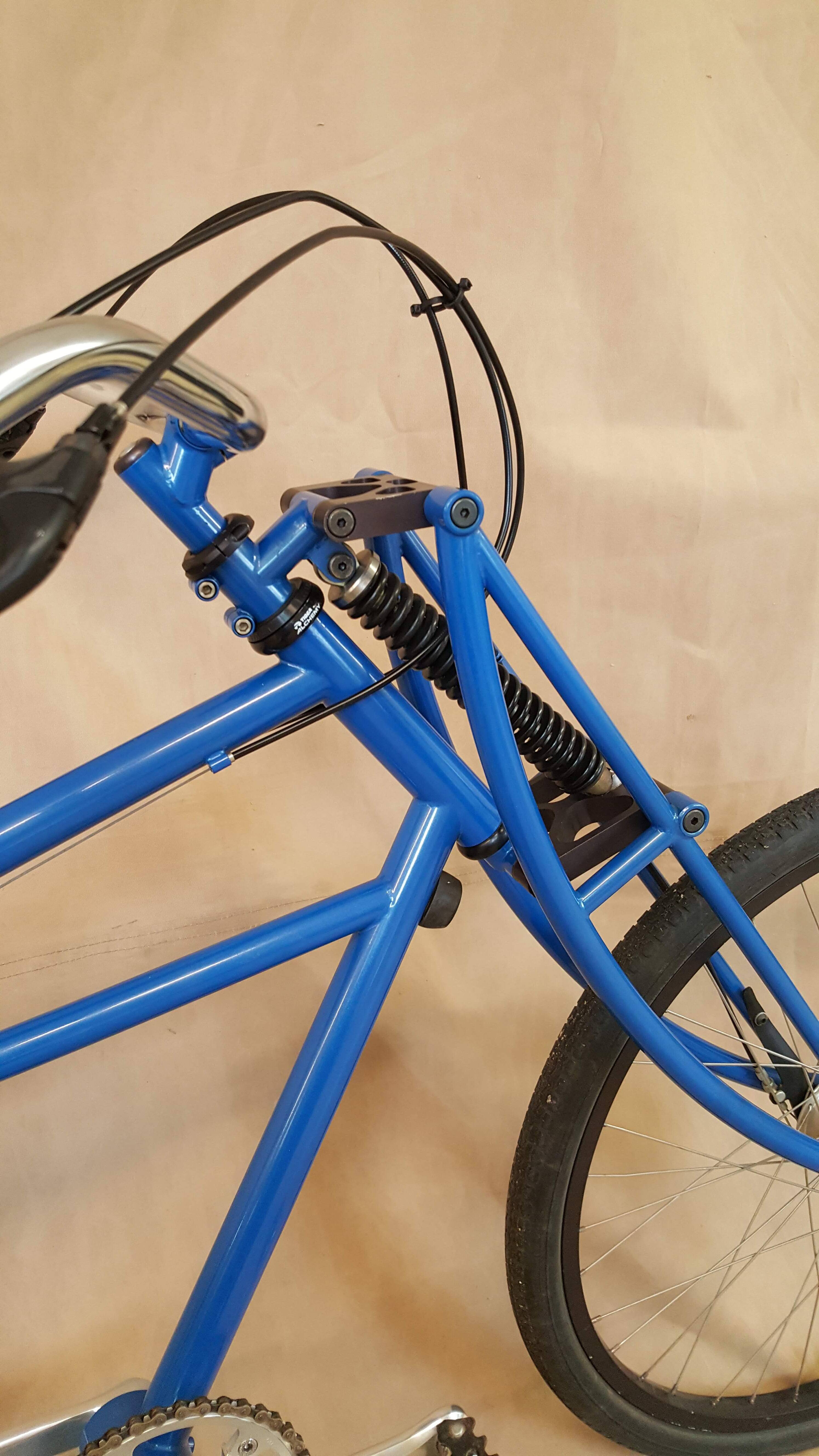
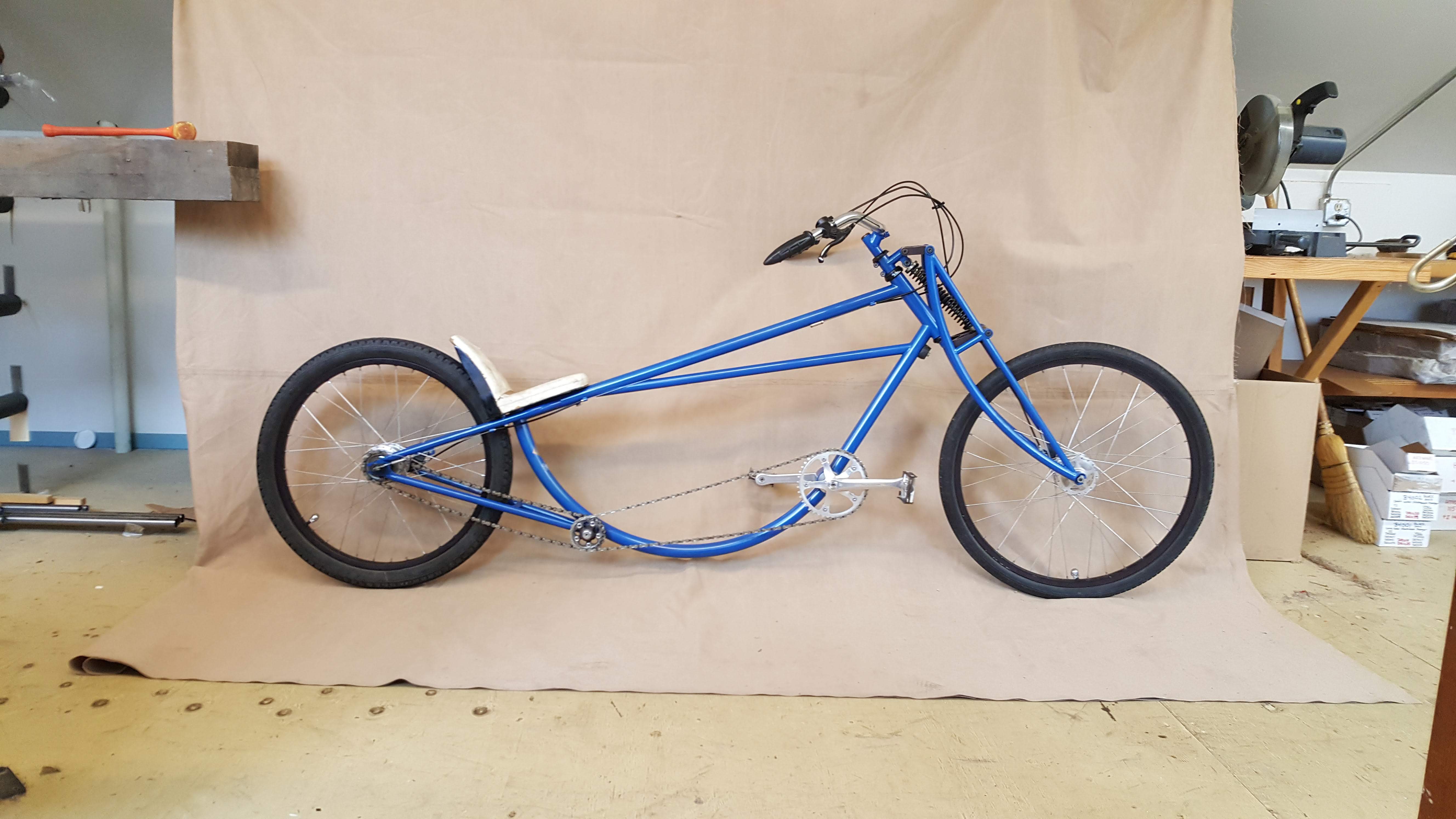
Here’s mine from 1995. No shock, just a spring. It was inspired by an Indian motorcycle. All style, no performance. I could almost fit a Sportster motor in there…
I love it! I think that is now one of my all time favorite bikes. How was it to ride? looks just a little stretched out. How did you determine the links design? Did you prioritize axle path, offset, or something else I haven’t thought about yet?
Make it! I still think the Girvin/Noleen forks were very nice to look at. One downside I found with my Proflex 5000 is that the fork moved backwards when compressed which made it interesting to ride on steep terrain with big holes. But I have been thinking about doing a gravelversion…
Yeah, a bit stretched out, with a lot of wheel flop. Low speed takes some getting used to, but it gets stable at higher speeds. Link design was to make an a approximately linear motion parallel to the head tube, nothing innovative. Glad you like it!
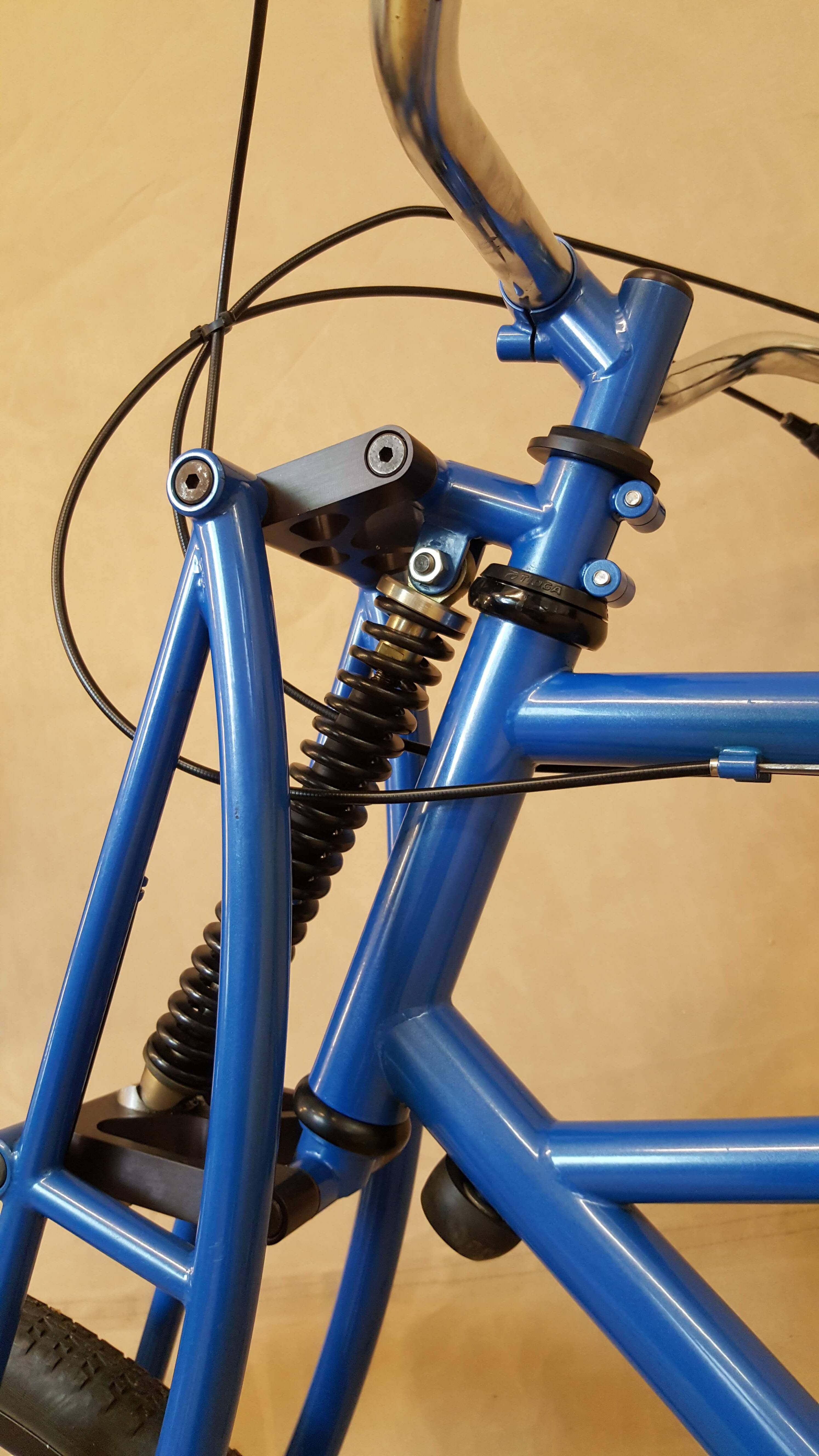
I think one issue could be small bump sensitivity - the short linkages combined with an air shock may result in the system being “sticky” over small bumps. Girvin used steel springs. I could be totally wrong though.
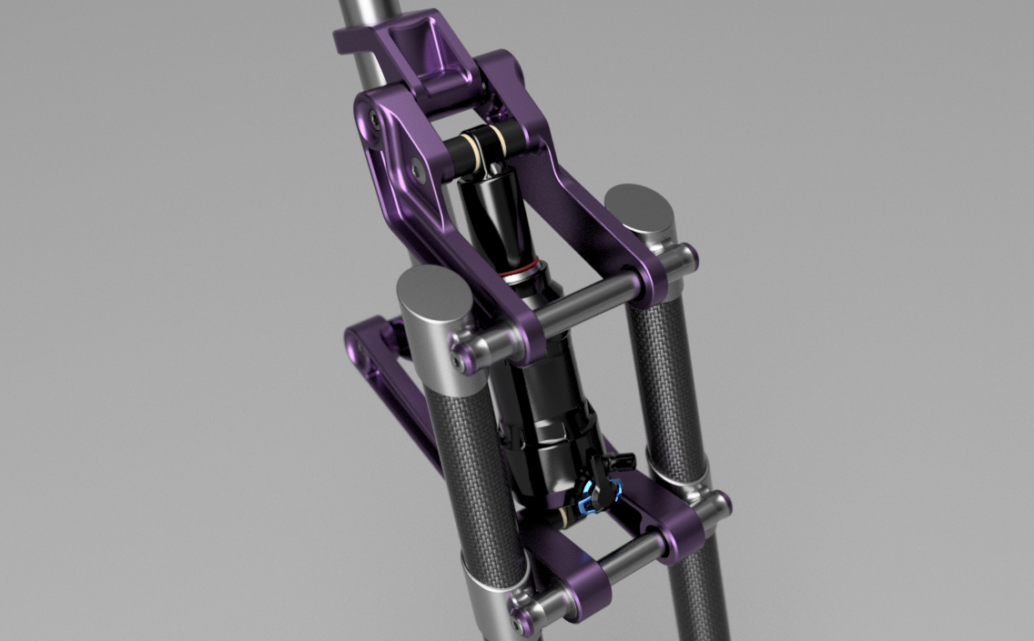
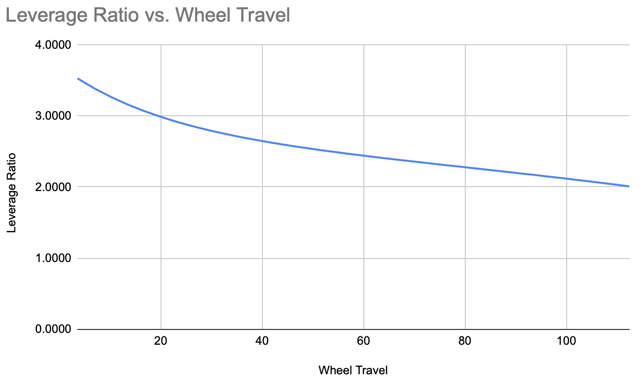
I was able to manually create a spreadsheet with an equation to spit out the leverage ratio. This is not completely accurate, but I think it’s close enough. It’s pretty progressive in the first bit of travel which should help the initial stroke be sensitive. I just hope it’s not too progressive. With it being this progressive, it might be hard to access the full travel. I might play around to see if I can change that. I also want to try to create a chart for axle path.
Considering that you also have a small volume air-shock to add to that curve, it’ll likely be a bit too progressive. But since you have the spreadsheet you can multiple the shock curve by the leverage ratio to get a wheel rate and then compare back to a coil fork (remember those!?!?!?) and a comparable normal fork.
I think I’m just gonna have to DM you. That went slightly over my head. I actually don’t have a ton of experience with forks and taking them apart and putting them back together.
I built a linkage fork many years ago. It wasn’t nearly as nice as this one but I did learn one important lesson about flex.
Like your design, I had 4 separate links or arms. I found this was not enough to eliminate side load flex and it made for a very vague steering feel. Consider machining the bottom and top links as a single piece each or some way of solidly locking the arms and axles to eliminate twisting.
(This makes me want to fire up CAD and revisit linkage forks).
Can’t wait to see your progress!
I was hoping that someone would suggest this. I didn’t want to have to machine them out of a single piece due to costs, machine time, and material waste. I’ll probably do a simple re-design/addition of a bolt in brace to connect the two sides. Maybe I’ll find a way to have them mechanically locked in place so the bolts don’t take too much stress. kind of like a socket or something. Thanks for having experience in this area and sharing.
Also, feel free to steal any ideas from my design as you want. It’s a work in progress and any and all collaboration is welcome.