Mitering tubes accurately

I’m designing my bike in CAD (Onshape) and have the frame laid out but am wondering how everyone miters their tubes accurately. I have a manual mill and a lathe with a hole-saw that I intend to use for the purpose. My question is how to align the hole-saw accurately. One fully manual way I’ve seen people do it is to get a 1:1 print out of the frame - mark the edges of copes with a pen on the tubes and align the hole saw edge to it and go from there.

Another one is to 3d print templates and draw them out on the tubes and align the hole saw with these manually. This also works, better than the first one above but still quite a ‘visual’ method. Wondering if there is anything better?

Coming from a CAD / machining background I was hoping for something more precise like using an edge finder / etc and then backing off a manual mill some distance away. How do you guys accurately measure:

  1. Length of tube to cut.
  2. Where exactly to notch?

Is there a trick / method that doesn’t rely on doing it visually? Thanks!

Bike is here for anyone interested:

Its going to be my first bike frame - for my 6yr old!

1 Like

“Miter to miter” is a common number for building. Generally it is the deepest part to deepest part of each miter on either end of the tube. Give yourself a datum point to reference from eg. your tube centerline at the deepest part of the miter (the middle of the scoop, right on your centerline).

For stock tube length if you use your center to center measurement on the tube that should be long enough, eg. ST to HT center to center, actual, not effective.

Most of custom framebuilding requires a good visual/reference acuity. Unless you are building the same models/sizes over and over, it’s easier and faster to do it by eye.

If you have a mill and DRO, you could always zero on your first cut and crank the table over for the next cut, but you will still have to adjust the tube for mitering angle and unless you have a big table and multiple clamps it will probably be more effort than it’s worth.

There are also main tube mitering fixtures you can buy, Sputnik makes one. But they are $.

1 Like

You can easily use mitre templates to help set up for hole saw cuts or you can just use them to rough cut and file the mitre in.

I’ve found even with using hole saws they are handy for planning out the finished tube from the the stock tube. ie. butt lengths etc.

Roll teh tube to find teh spine, mark the spine, use the templates at the req’d distance apart. It’s a good safe guard to also making sure you are in phase. I’ve done a couple top tubes where I end up 180 degrees out. Not the end of the world but means you have to grab another tube.

1 Like

You should check out this thread for a general discussion about tolerances. Even using a mill/lathe, you’ll probably be hand filing to get the best fits possible. Which could marginally change the length and angle of the next miter……which could change the length and angle of the next miter…….

Don’t stress about hitting the CAD dimensions perfect, leave yourself wiggle room with your hole saw and walk the miter in with a file until it fits tight.

3 Likes

And to actually answer your question, I trace paper templates on with a thick sharpie, using a straight edge to set the distance. I start doing test fits when I hit the outer edge of the sharpie line, and when the miter is finally tight some edges will still have a lot of sharpie showing, other edges it will be completely gone.

1 Like

I have never used a miter template, and don’t really understand how they would help. Maybe that’s my ignorance but it seems they’d just slow you down, for machine mitering (hole saw).

All you need is a scribed layout line to bring the hole saw down on. Blue it first (Sharpie) if you want the scratch to be more visible.

The shape of the miter, and the overall length of the tube, is handled automatically by the hole saw.

You may wish to start with two scratch marks, but the first cut can be almost anywhere, so generally you make the first cut by eye, maybe to a Sharpie mark, and only then do you get out the precision tools to mark where the second cut goes.

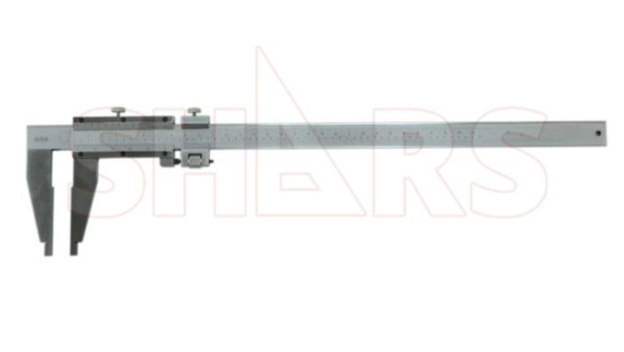
I like a precision rule (aka “yard stick” only more precise and made of steel), with a beam trammel to transfer the measurement and scratch a line where the second cut will go. You can use the top or the bottom of the tube, and scratch to mark the deeper side of the miter (e.g. bottom of a DT at HT) or the shallower side (top of a DT at HT), depending on how you like to hold the tube when cutting. CAD will give you the dimension to use in either case, just remember the lengths are different on the top and bottom of the tube except for the specific case of a TT where HTA = STA (parallel frame abgles).

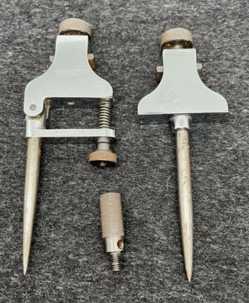
I like these Starrett-style trammel points, expensive to buy new but here’s a used pair on ebay at the mo for $35
Ah these are even cheaper 'cuz free shipping.

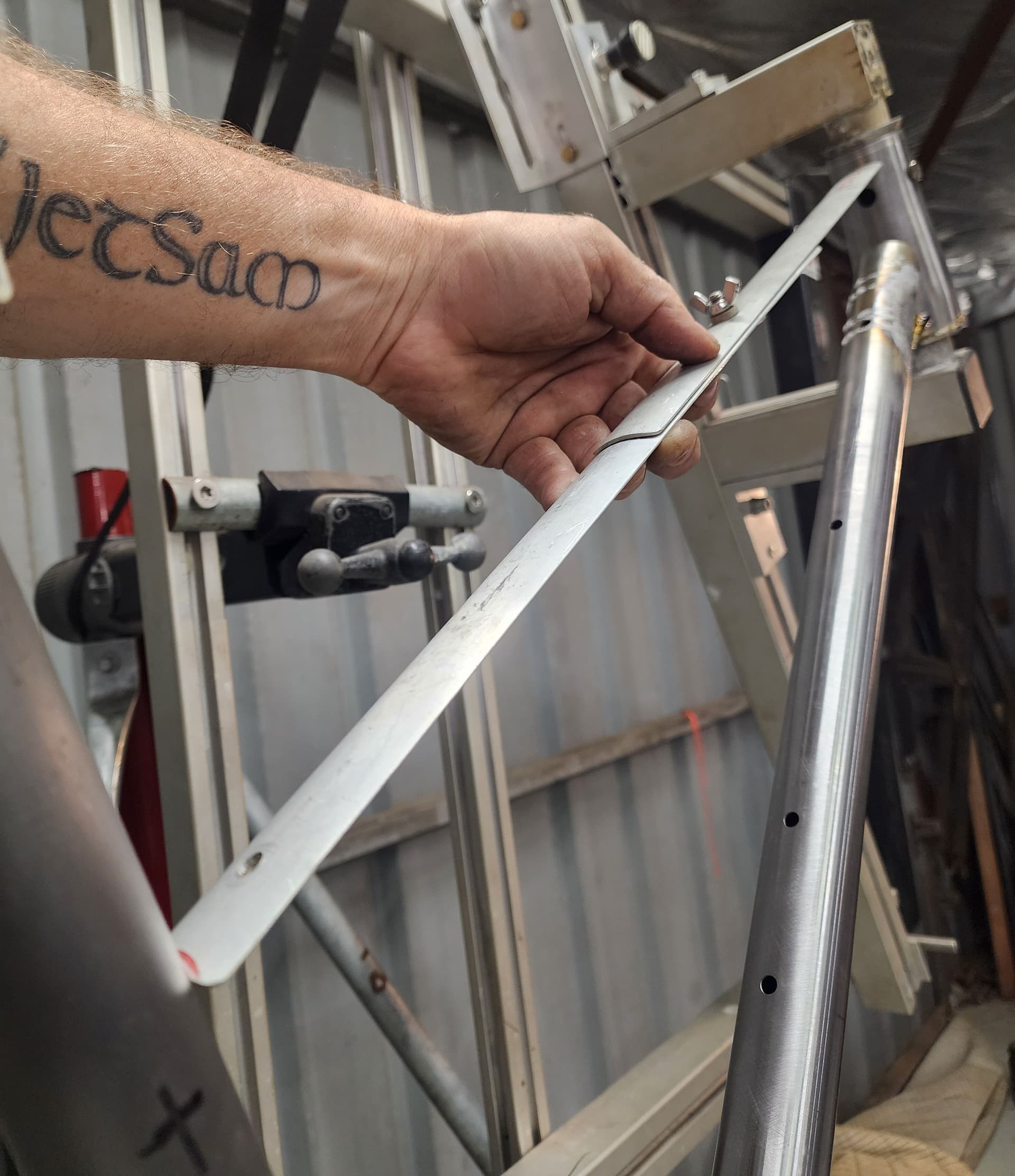
You supply your own beam, which can be steel, alu or even wood, though rigidity is good, so consider steel. Mine is alu and it’s rigid enough with some care not to flex it in use. I apply a slight amount of “preload” while setting it on the rule and then match that, same amount of “feel” while transferring it to the tube, to minimize the effect of flexing the beam.

To mark the second cut on a DT, you need transfer the measurement 90° around the circumference. I use a ring that snaps on, held by friction, with sides machined parallel. Part if off on the lathe, then cut it so it’s a “C” instead of an “O”. A bit hard to describe in words but you’ll quickly see how to do it once you have the tube in hand. Not needed when the cuts are in the same plane, e.g. toptubes.

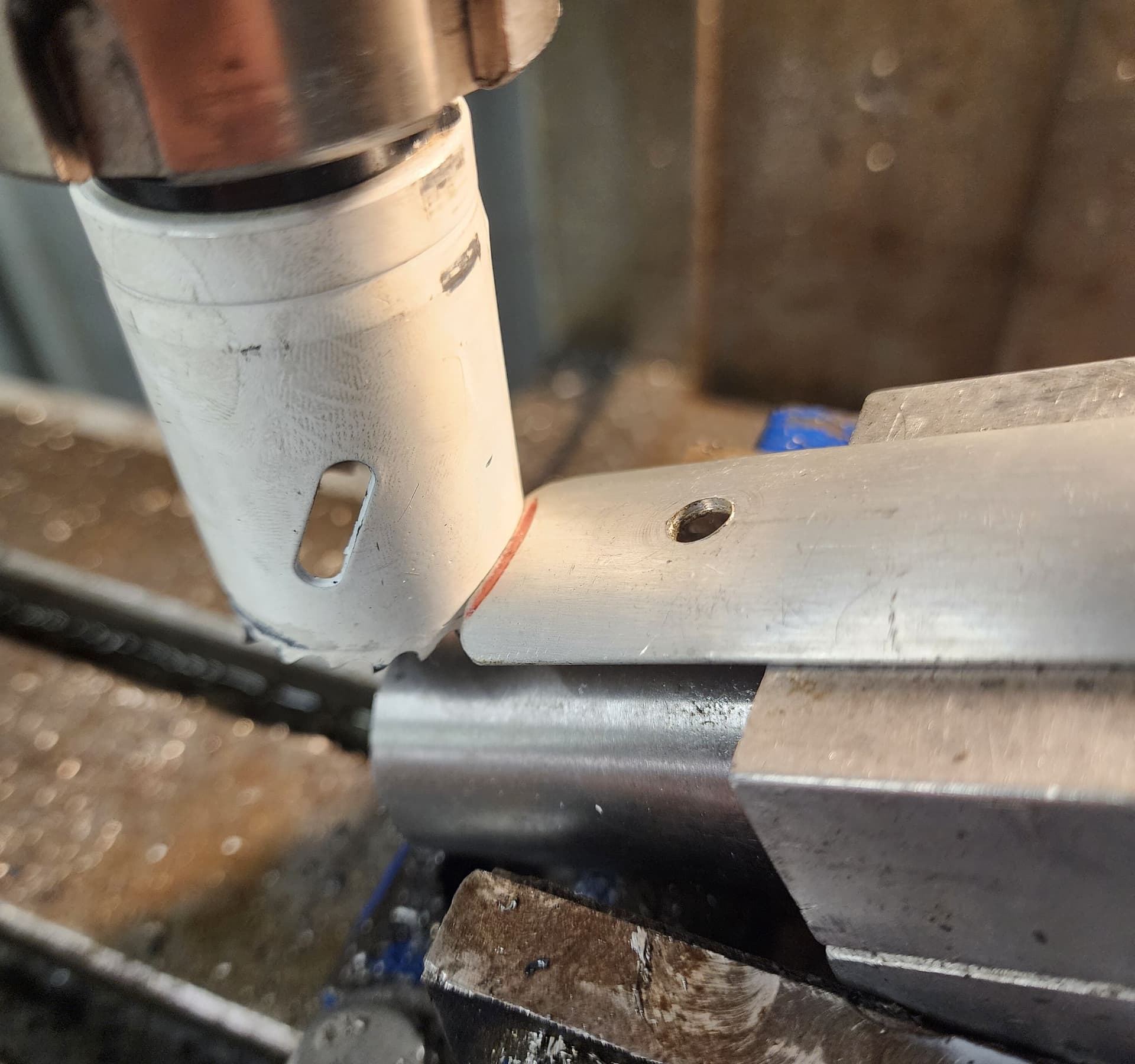
My hole saw miters almost always come out essentially perfect with no hand-filing needed beyond thorough de-burring. I use fine-tooth holesaws, welded bi-metal type, and replace them when they get the slightest bit dull (they’re cheap enough). Get Paragon (PMW) arbors, cheap and good! Buy enough for all your sizes of holesaw so you can leave an arbor in each saw.

Bringing a holesaw down on a scratched layout line is probably precise to a half-mm easily enough, more like 0.2 mm or better with practice, good eyesight and bright shop lighting. Times when you need more precision than that? Just about never.

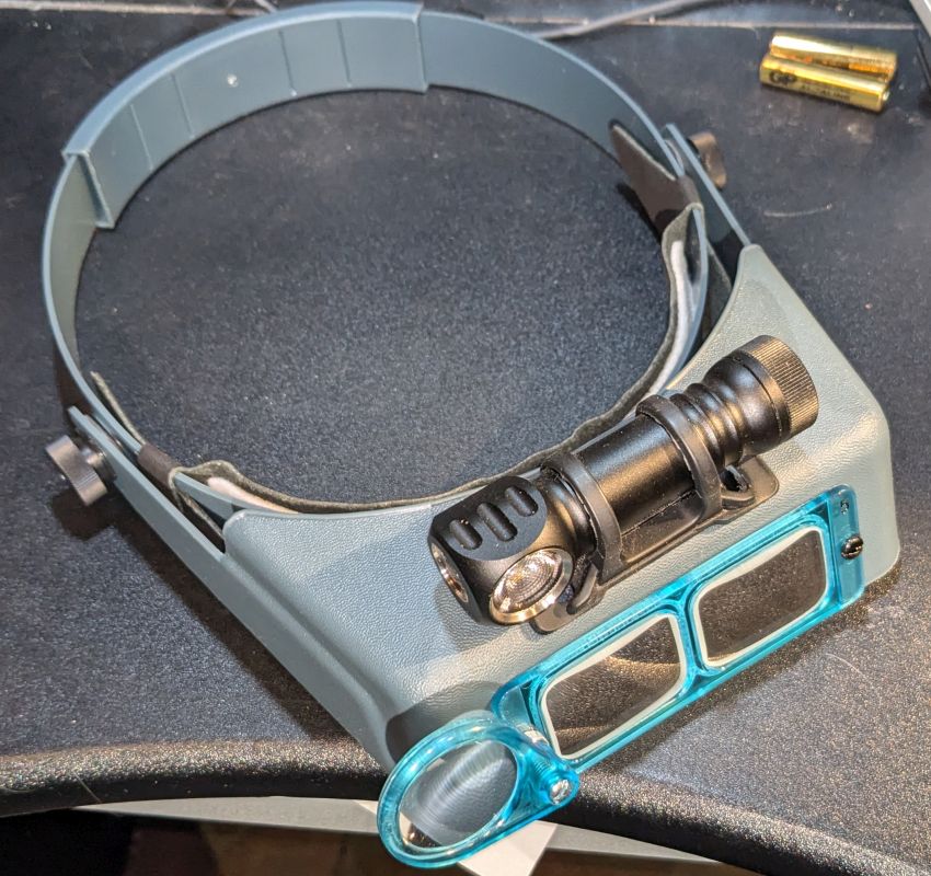
If your eyesight isn’t the greatest, bifocal safety glasses or the ultimate, an Optivisor with a strong LED work light attached.


They don’t come with the Zebralight attached, I had to drill holes and zip-tie it on. It’s godlike for hitting a layout line or centerpunch, also for getting tiny slivers out of your flesh with tweezers.

7 Likes

Thanks all!

@bulgie I’m gonna go with your approach. This makes a lot of sense to me coming from a machinist background. I’ve never used a beam trammel before so pardon the dumb question - seems like you use a parallel beam (say a alu extrusion) alongside the tube (and maybe slightly elevated) and use the sharp end of the trammels to measure deep-miter to shallow mitre (or any combination as long as you sure what you measuring). This may require using your C-ring to 180 transfer the scribe around the tube?

Then once you have the scribed line bring down the hole saw with the correctly dialed angle onto it.

I’m thinking I’ll use a similar approach - but instead of waiting for the scribes i’ll 3d-print some ‘sleeves’ which would allow me to measure the same accurately with long calipers.

Thanks everybody!

No, I never measure from the shallow side to the deep side of one miter — no need to. The trammel is for marking the second miter the right distance away from the first miter. Say it’s a TT, you miter the ST end, then trammel to get the layout line for the HT cut. One short scratch (I do maybe 6 mm long) per tube, because you don’t need to know where the hole saw will come out on the other side of the cut, the angle you’ve set will take care of that for you.

As for how to set the angle, I trust with your machinist background that’s no problem. Most people angle the tube rather than angling the head on the mill, but one place I worked we did angle the mill head. It was only used for mitering, hardly ever for milling, so tramming the head back to zero wasn’t an issue. Horizontal mills and lathes are also excellent.

4 Likes

I understand what to measure - just not clear on how you use the trammels here - I’m guessing they mounted on some sort of a rail and you use them like a caliper?

For the angle I’ll just use some paragon tube blocks to lock the tube in a vise (and index it) and use a electronic level.

Thanks!

1 Like

Yes, they’re like a caliper that opens to 26" (or whatever your longest miter length is). The beam that goes thru those Starrett points I linked to is 3/8" wide x 3/4" tall, and just needs to be longer than your longest miter you ever want to be able to do.

BTW Starrett also made trammels just like the ones I linked to only with both points fixed, not pivoting, and those are not suitable. You need one with the spring-loaded fine adjusting knob on one of the points. You do the coarse adjustment by where you place the points on the beam, then use the thumbscrew for the fine adjust. Fixed trammel points are for woodworkers I guess, where precision stops at 1/8" or whatever. :wink:

(Please don’t beat me up for that, you woodworkers out there, you know I’m just jealous of your mad skillz with dead trees.)

5 Likes

gotcha - I now understand how this works. Since I’m impatient I’m going to simulate this by printing some 3d-printed tube blocks that have a trammel like cylinder going in that can stop at the edge of the cut. It will also provide a nice flat rest for the calipers.

Thanks!

1 Like

In place of a beam trammel, I have used a 1000mm length of 3/4" x 3/4" x 1/16" angle aluminum extrusion with an adhesive measuring tape added. Zero on the left since I’m right handed.

This can also be used for marking the lengthwise centrelines.

For transcribing the mitre line 180°, I have used half a Paragon tube block, and even the edge of a 6x4" ruled index card wrapped around (use the ruled lines to get it straight).
For actually aligning the tube 0°/180° for cutting, I use a tube block as reference and flip it.

All the best,
Dan Chambers

1 Like

I use one of these 40" calipers. This is what Dave Bohm taught me to do. It works great. I tape a short piece of 1.6mm brazing rod to the inside of the fixed leg so I can reference the deepest part of the miter when doing the second cuts on DTs and TTs.

2 Likes

That’s what I use as well. I also use it to set my fixture off of reference ledges.

A caliper that long is a good way, but expensive, and I still like my trammel points better because I can scribe a line with them.

I worked at a shop that had the huge caliper, but after trying it for a while, I went back to my trammel.

The sliding doodad by @DevlinCC might be the ultimate in ease of use though. Gotta make me one! (What’s that tool called by the way, has it got a name?) Sorry I didn’t make a note of what thread that was in. I saved the pics though:


No measuring! Not in numbers of mm anyway. If turning it into a number is digital, then this way is pure analog. Respect.

I see one way for error to creep in though, by paralax, due to the measuring doodad being elevated to go over the tube-clamping block. It’ll only cause an error if the HTA and STA are different. Maybe the error is too small to worry about and/or @DEVLINCC compensates for it somehow. Or I’m thinking about it wrong, yeah it happens sometimes…

4 Likes

The calipers are a bit heavy and therefore cumbersome.

Not quite sure whether to ‘admit’ this here or whether it’s helpful but the way I do it is to not go for bolts first time.
I take all my angles off the computer, hit the critical end first - head tube or BB or ST end. Usually one cut is all that’s needed there unless I’ve read something wrong. Then basically walk up to the perfect fit at the other end.

For example, the TT which I consider the easiest tube in the frame: put a really nice HT mitre in leaving loads of butt, quickly check fit up, deburr and hone. Then literally offer the tube up in the fixture, mark my seat tube by eye and then go through with the holesaw. Takes me 3 cuts on a bad day and if anything’s out I’ve got time to adjust as I walk up to it. Most often it’s 2 cuts, if I’m lucky and my eyechrometer is calibrated I’ll nail it in one and move on.

~10 mins and the fit is :ok_hand:

4 Likes

The parallax would add some error, mathematically at least - but you have to raise “the doodad” because of the locking hardware bulging out under it.
Also the two sliding pieces are not aligned but one on top of the other, that adds to a possible error.

That said, I don’t think it’s noticeable and I will definitely make one for myself!
But I also got myself some trammel points, thanks @bulgie !

3 Likes

Thanks mate. I haven’t thought of a name but your quirey has got me thinking. I’ll get back to you on that.

Yes going over the tube block can cause some error if you aren’t careful. to be honest I can’t remember how I got around that. I’d have to go back and recreate that setup. but that also prompts some design ideas as well if I was to make a better ‘mouse trap’

I just mitre one end where it needs to be then use a steel rule and a scribe (over some Sharpie) to mark the other end. If the mitre is out of phase, I’ll still mark it the same way but then take a set of callipers and measure the mark I’ve just made, from the uncut end of the tube and use that measurement to scribe the 90º out of phase mitre but from the uncut end of the tube.

Obviously this only works when the second cut is on a tube with a square end and not one that’s been cut previously.

I get the angles and lengths from CAD or BikeCAD.

I’ve never felt the need for anything more complicated and I only ever make one cut per end.