~~~ Nikomi Bikes

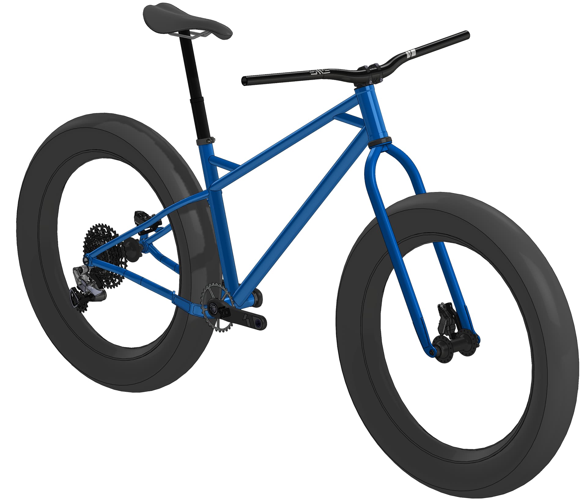
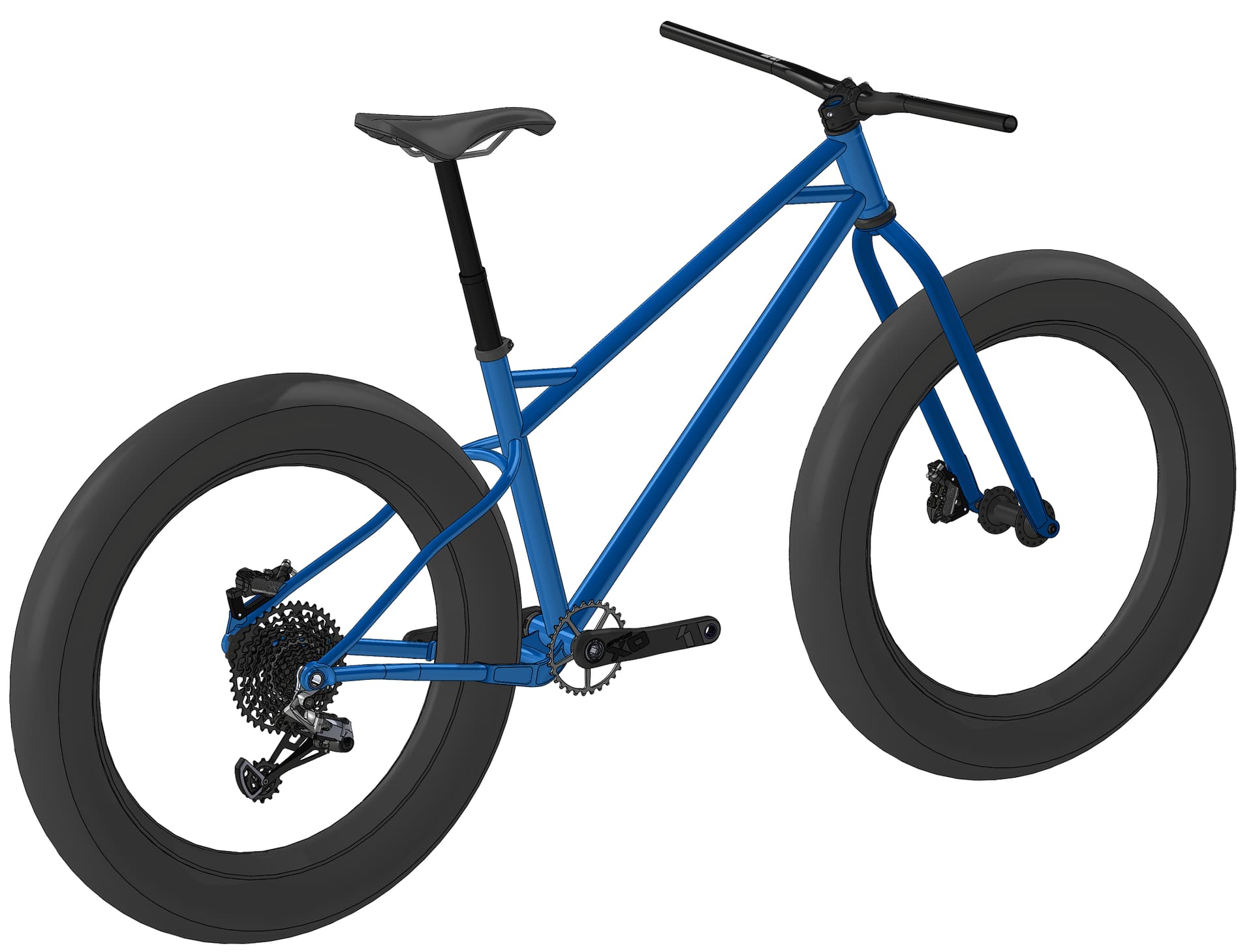
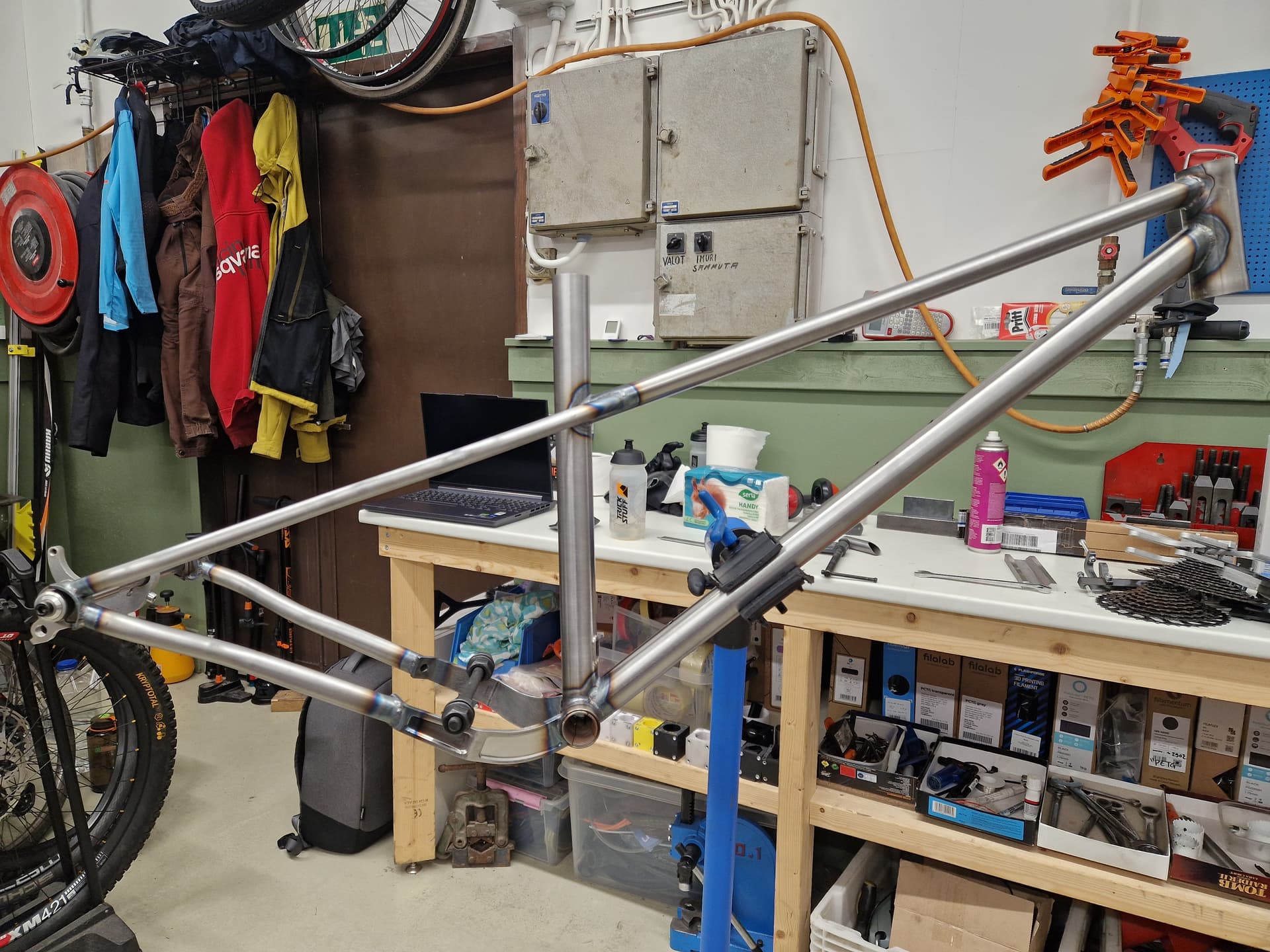
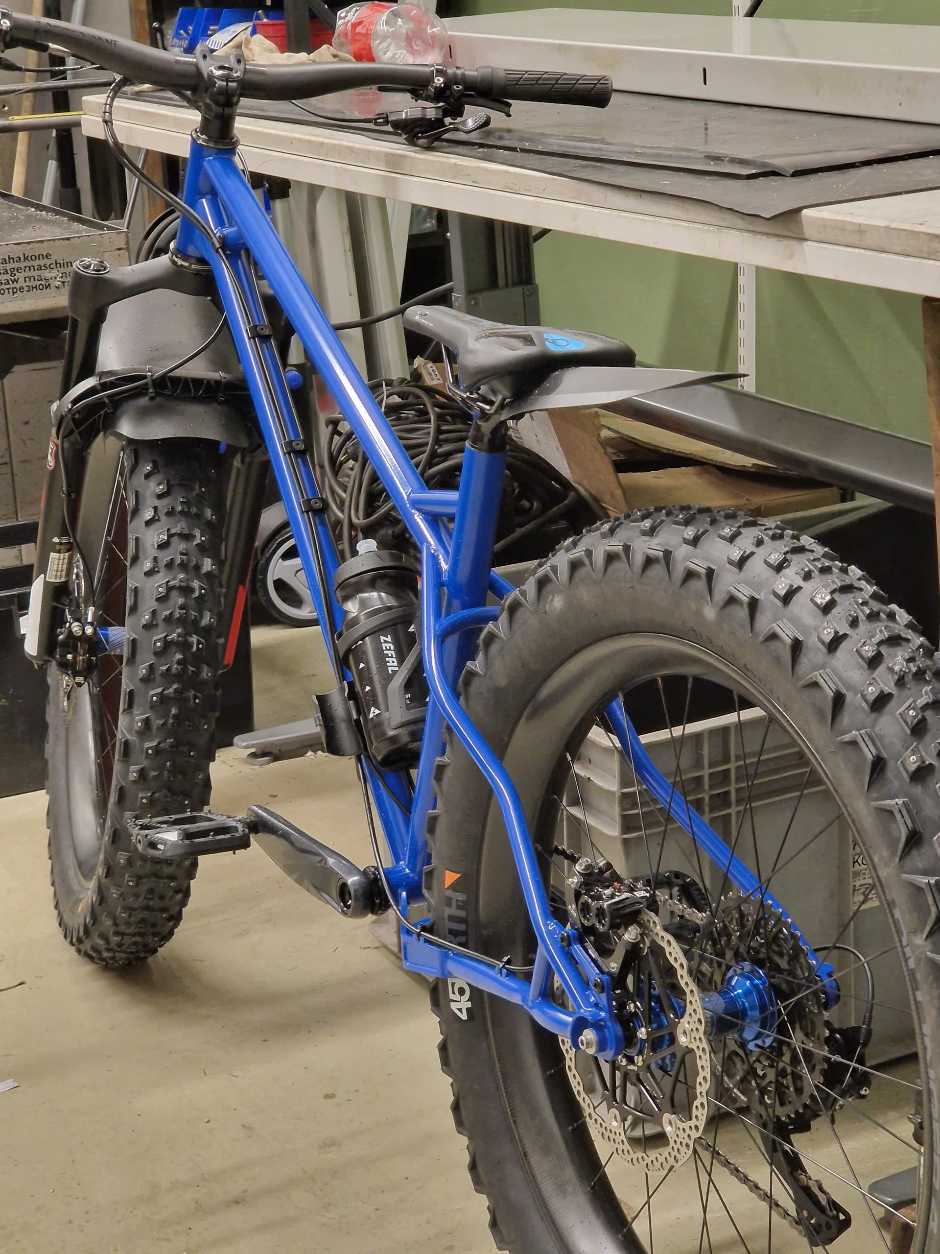
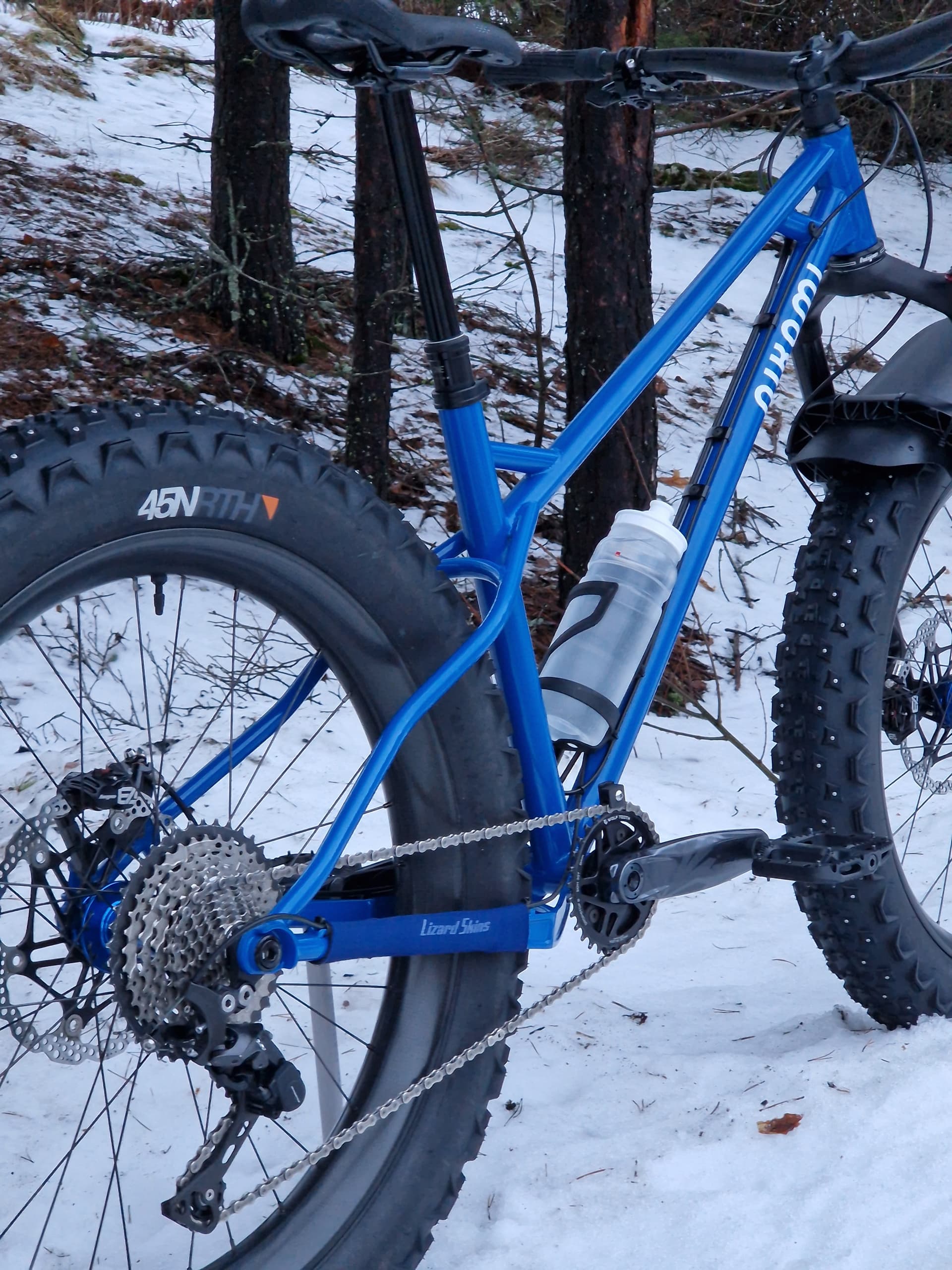
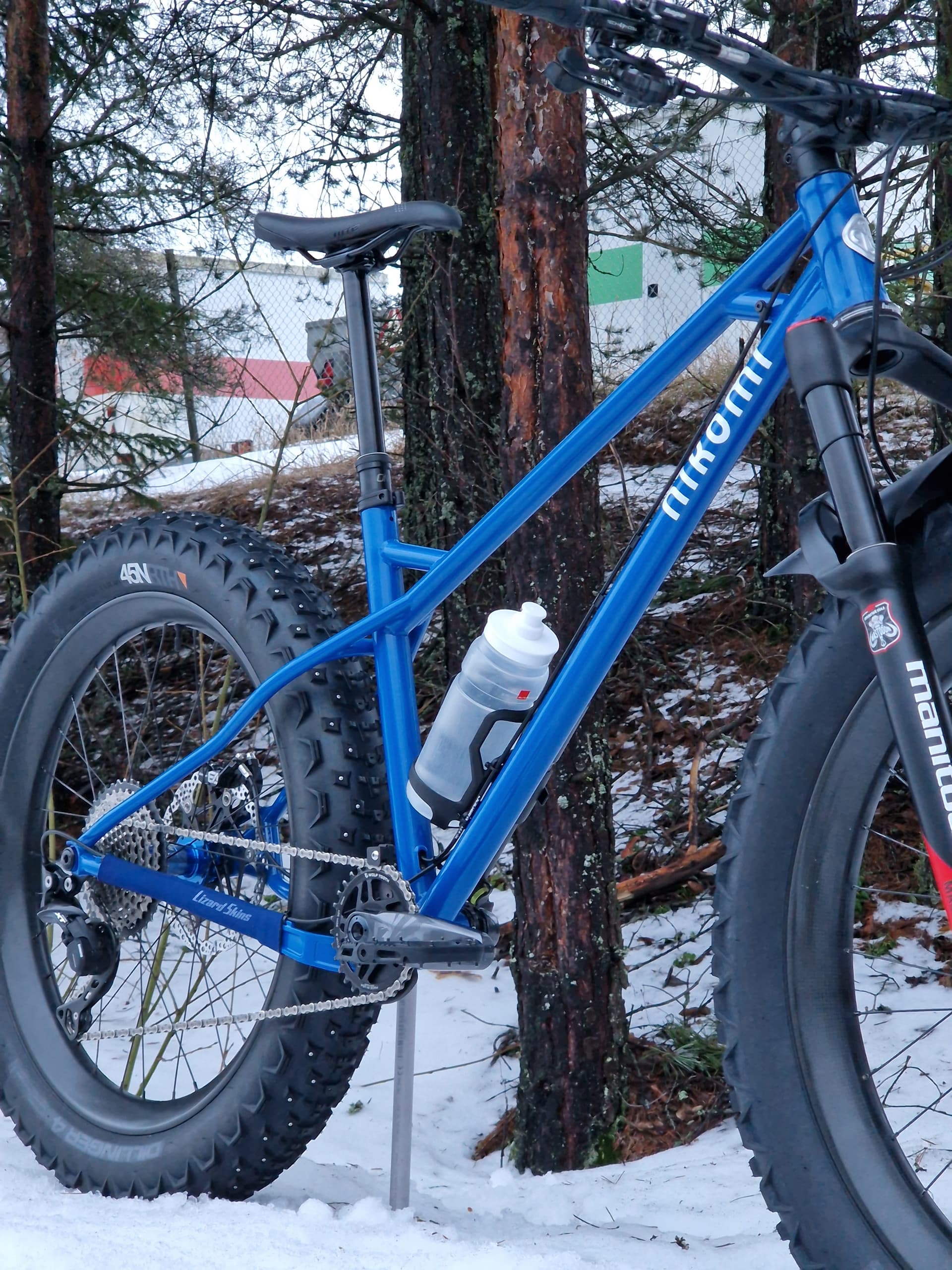
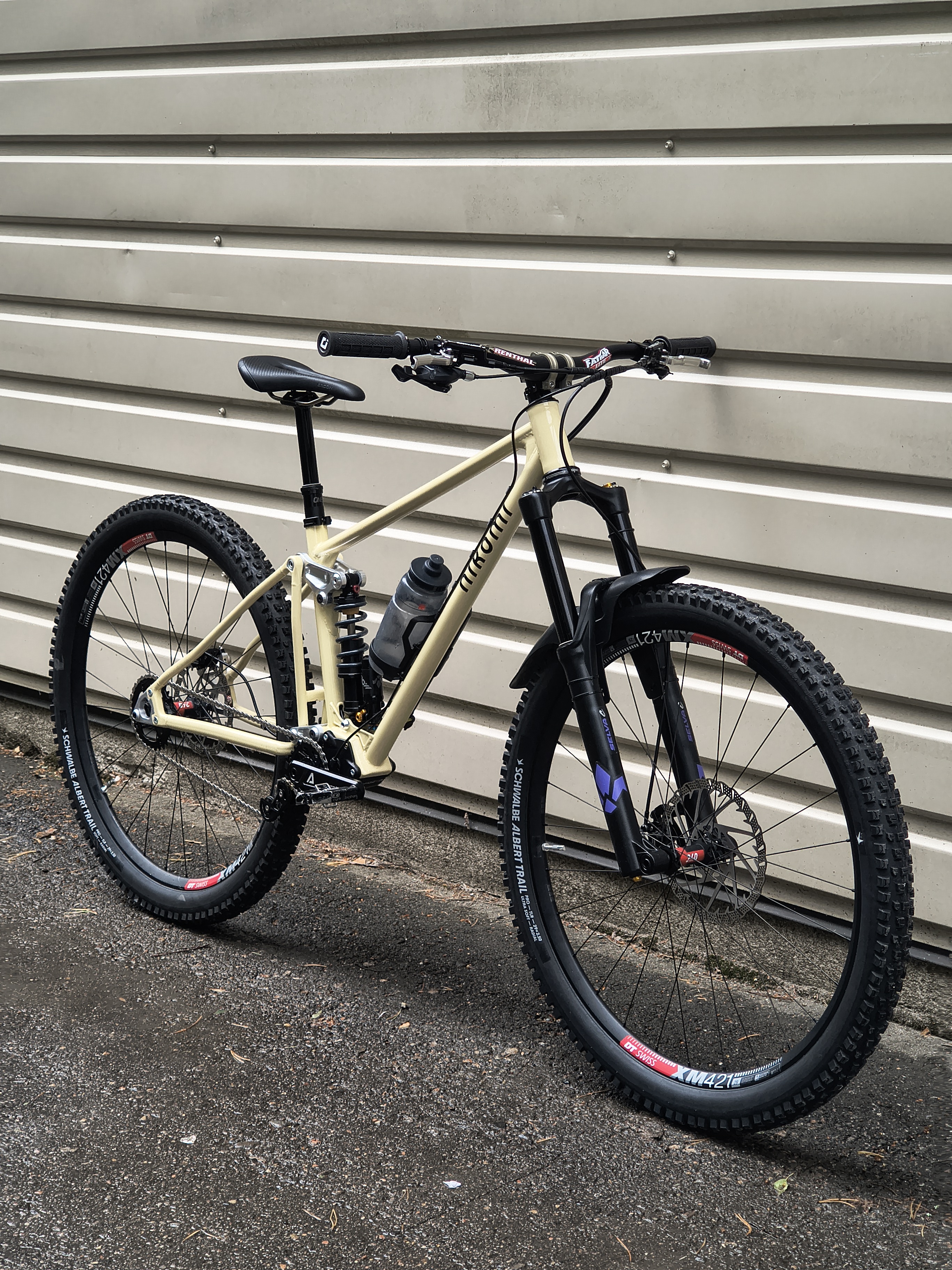
After the v1 was completed, I started to design a fatbike for me. I had a Trek Farley 5 before, which I mostly liked, but the geometry was a bit too traditional for me. The seated position is fine for longer days on the saddle, but most of my riding is on the local MTB / enduro trails in the winter also, so the short reach was something that was too different from my enduro bikes. Also, I had some knee pain occasionally, and my hunch was that the long 175mm cranks combined with the wide q-factor was at least part of the issue (I’m 170cm = 5’7”).

Also, the Farley 5 had 27,5 x 3,8 in the rear and 27,5 x 4,5 in the front. I often felt that the rear tire did bite well and had just enough float for me (on groomed trails with fresh snow), but the front tire was eager to wash out.

So the fatbike had to have enduroish geometry and somewhat narrow q-factor, with at least 26 x 3,8 tires.


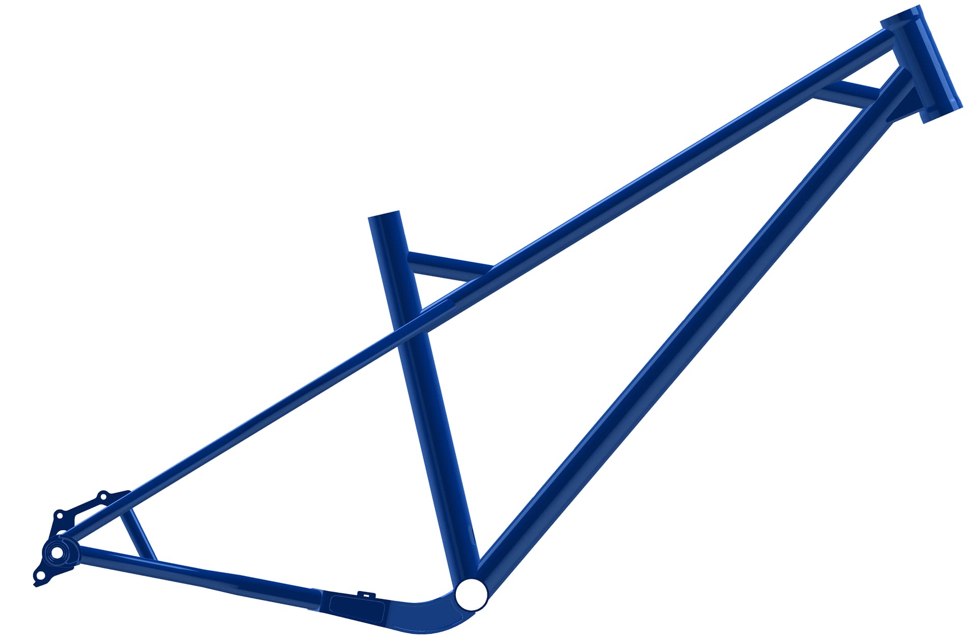
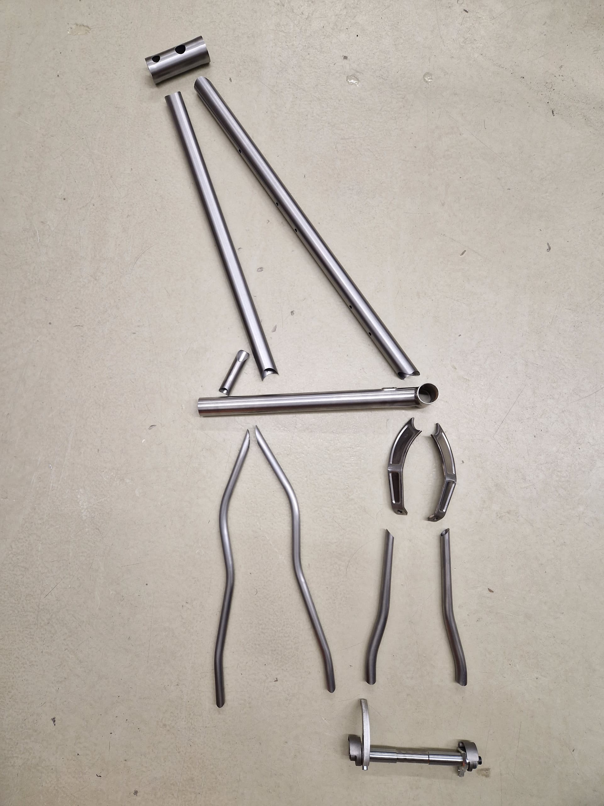
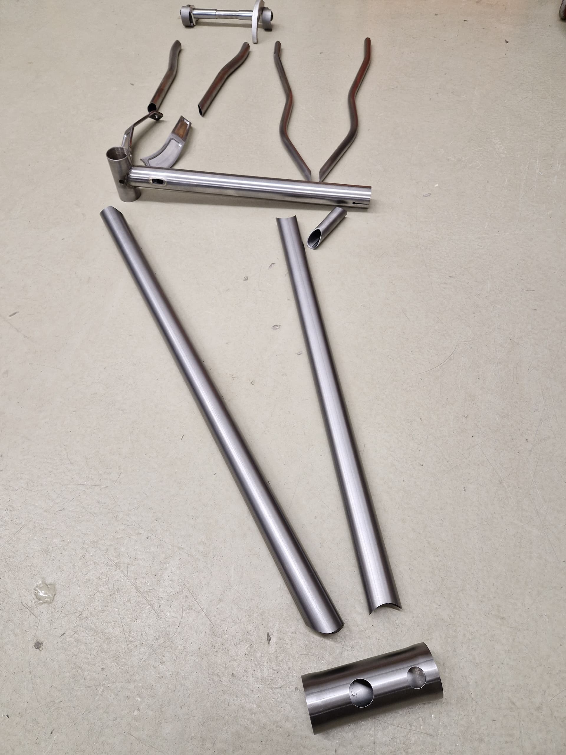
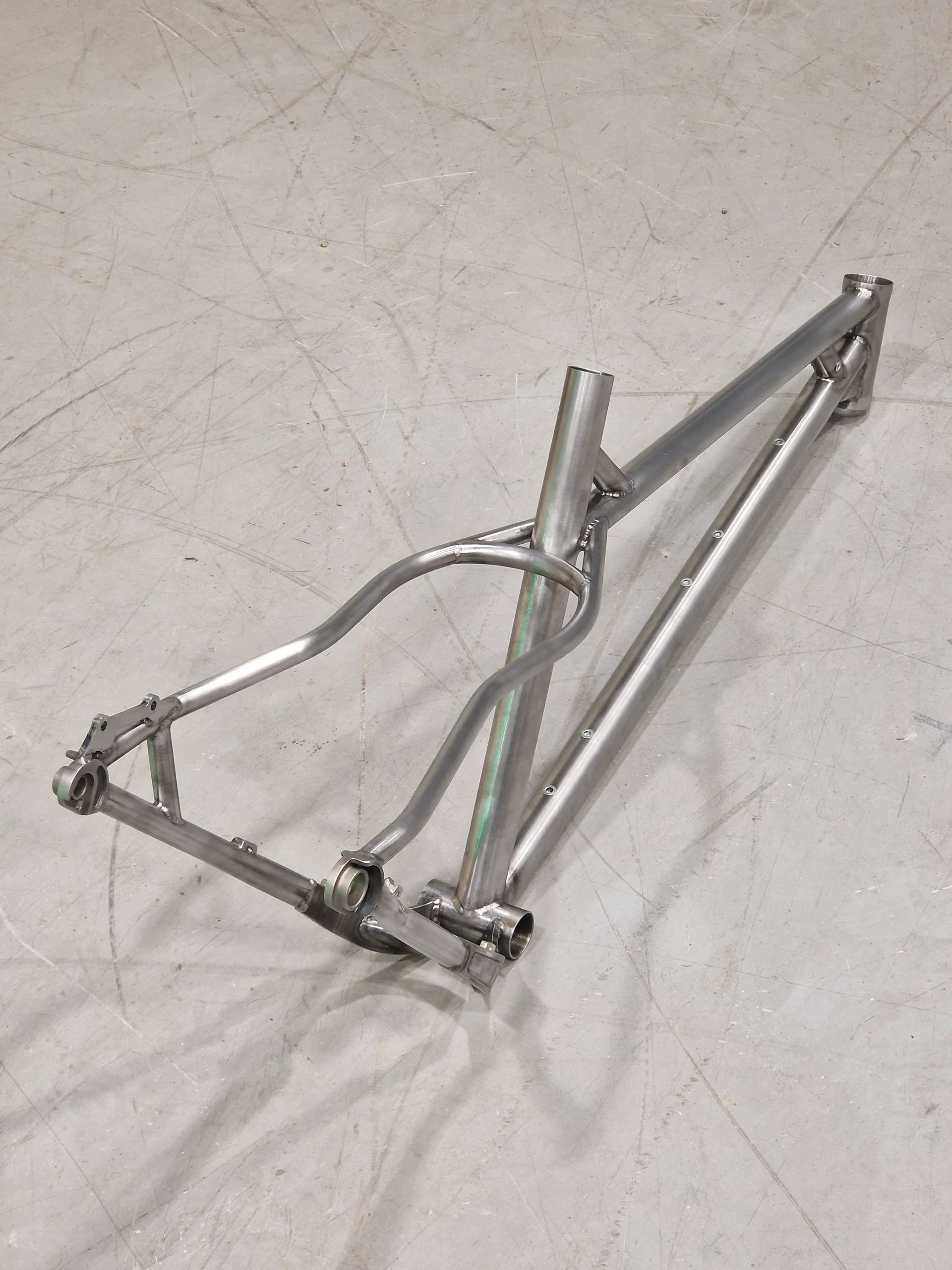
The tubing is basically the same as in v1, straight gauge Docol R8.

Downtube: 35 x 1

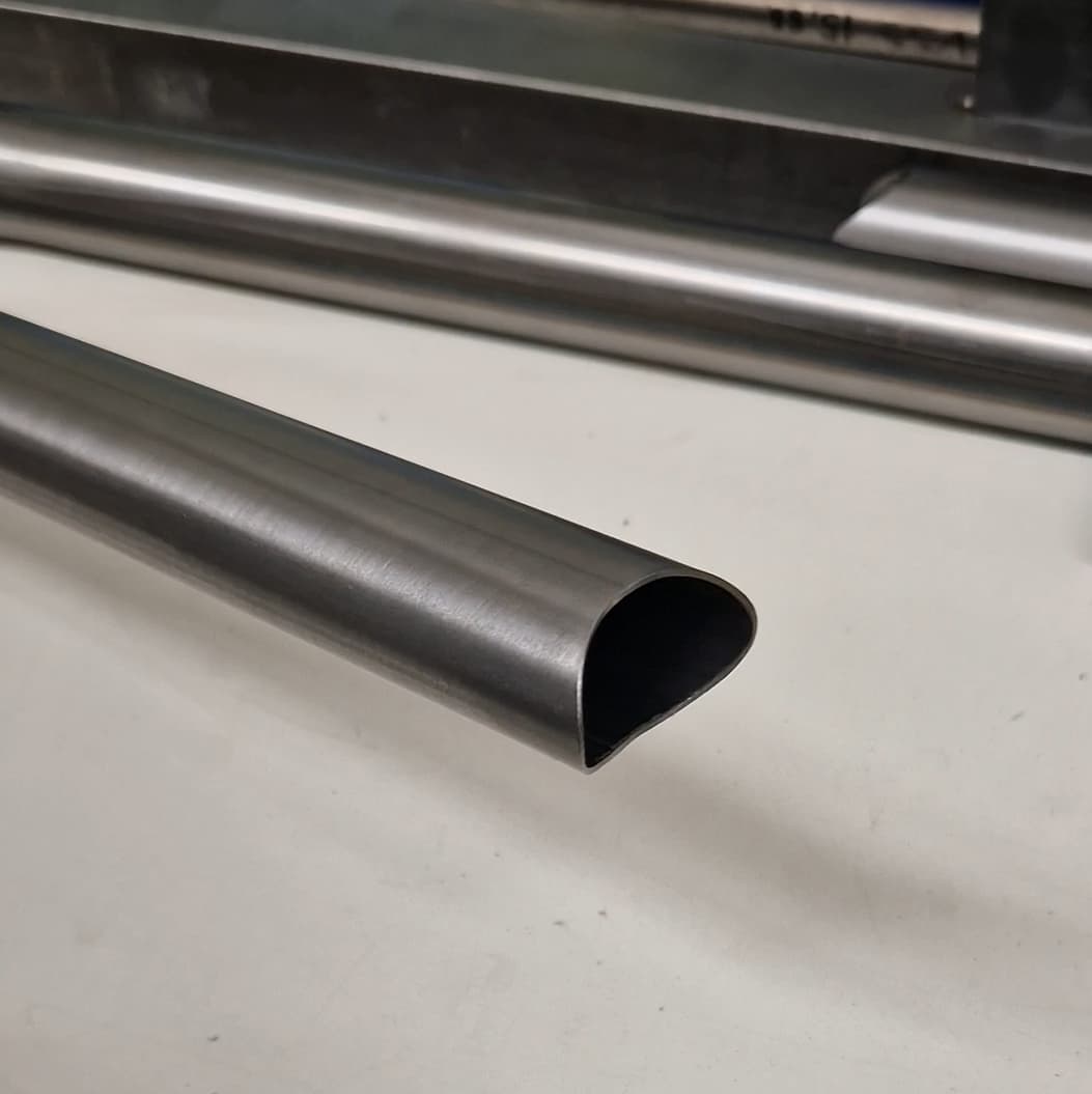
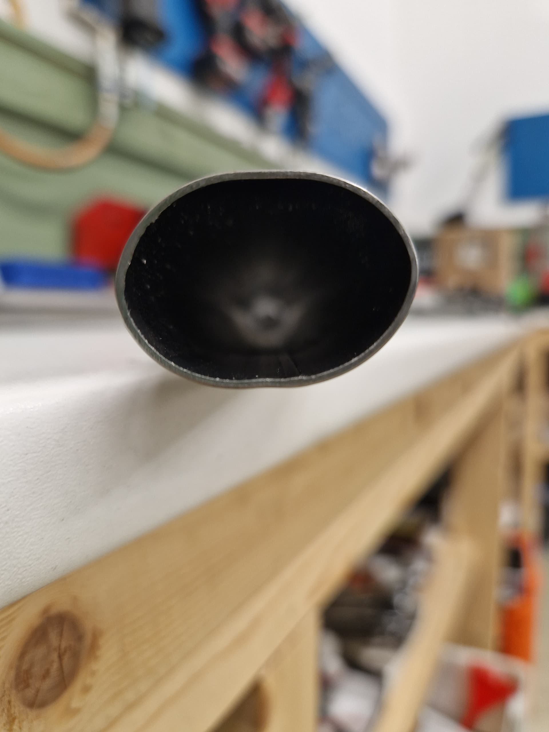
Toptube: 30 x 1 ovalized to ~ 35 x 25 x 1

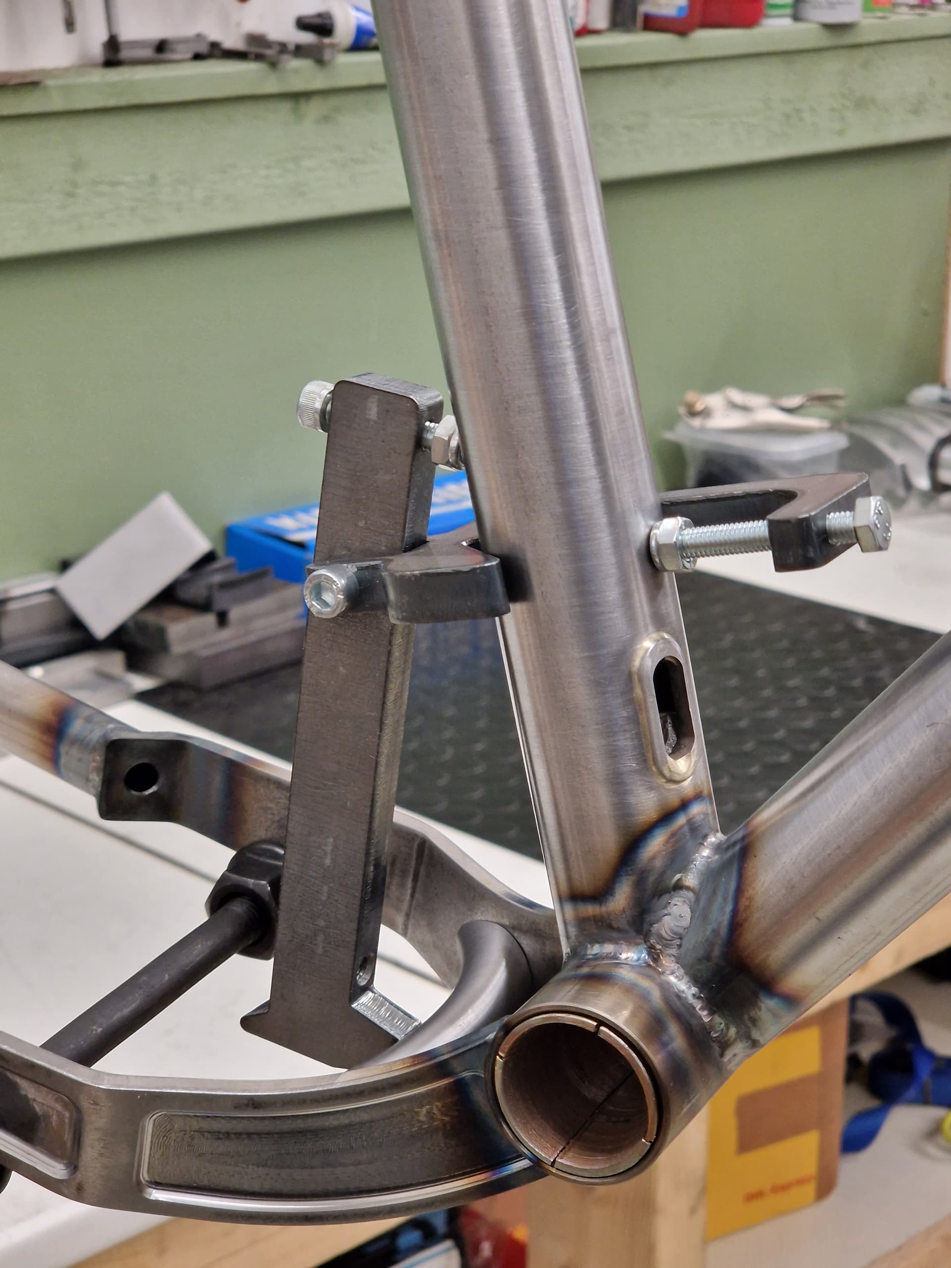
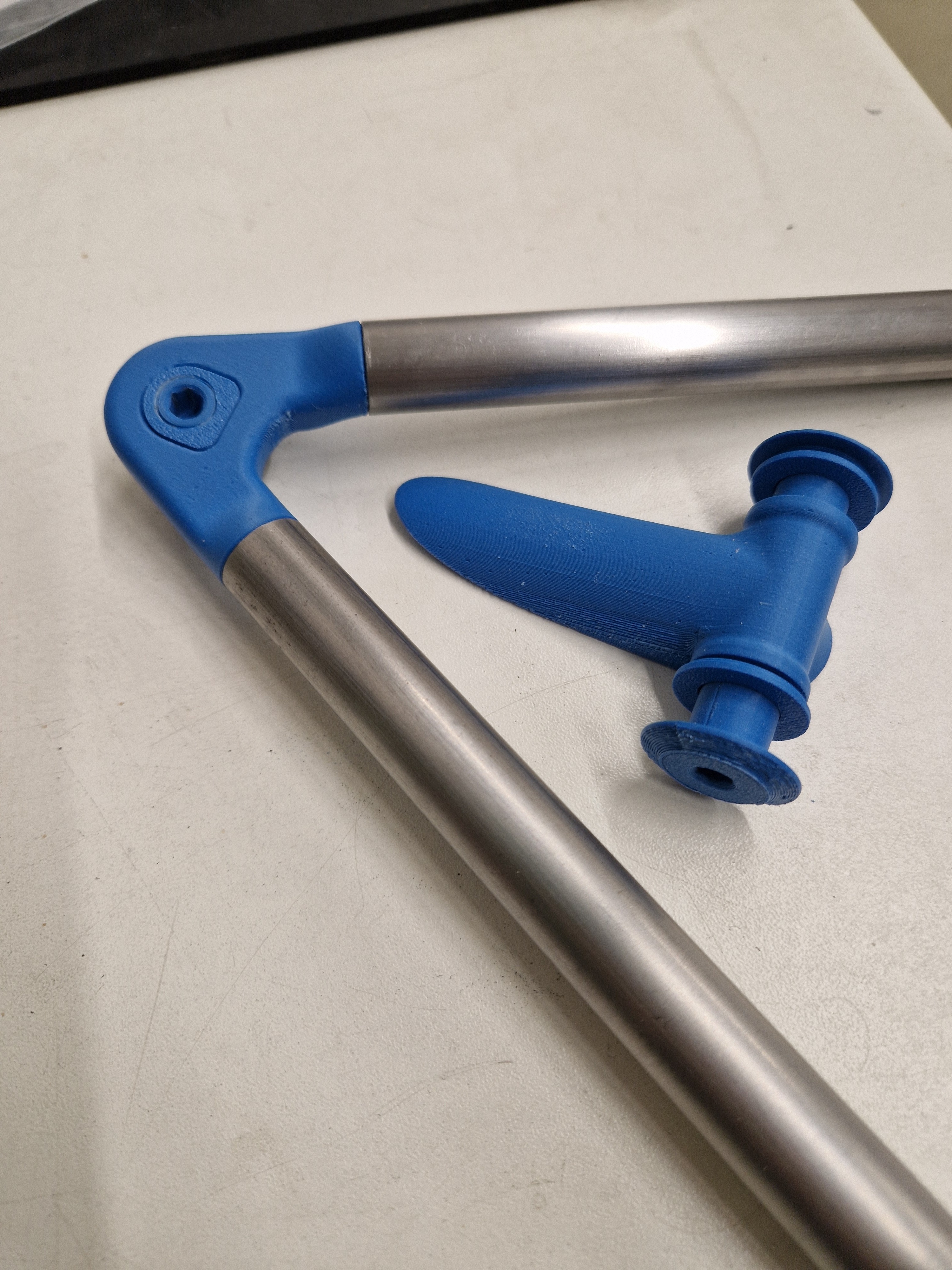
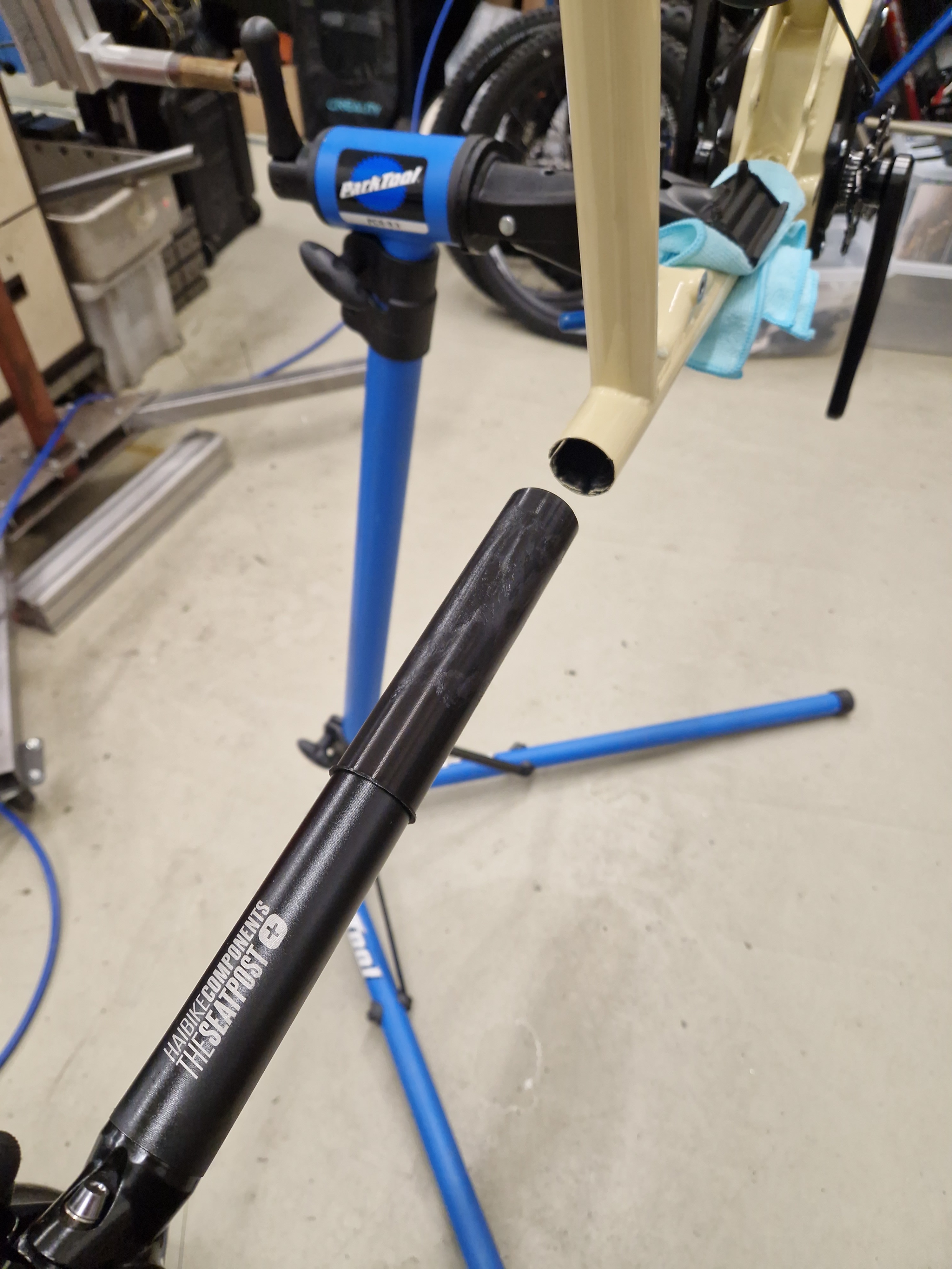
Seattube: 35 x 1 (with 3d printed PCTG insert to 31,6 id)

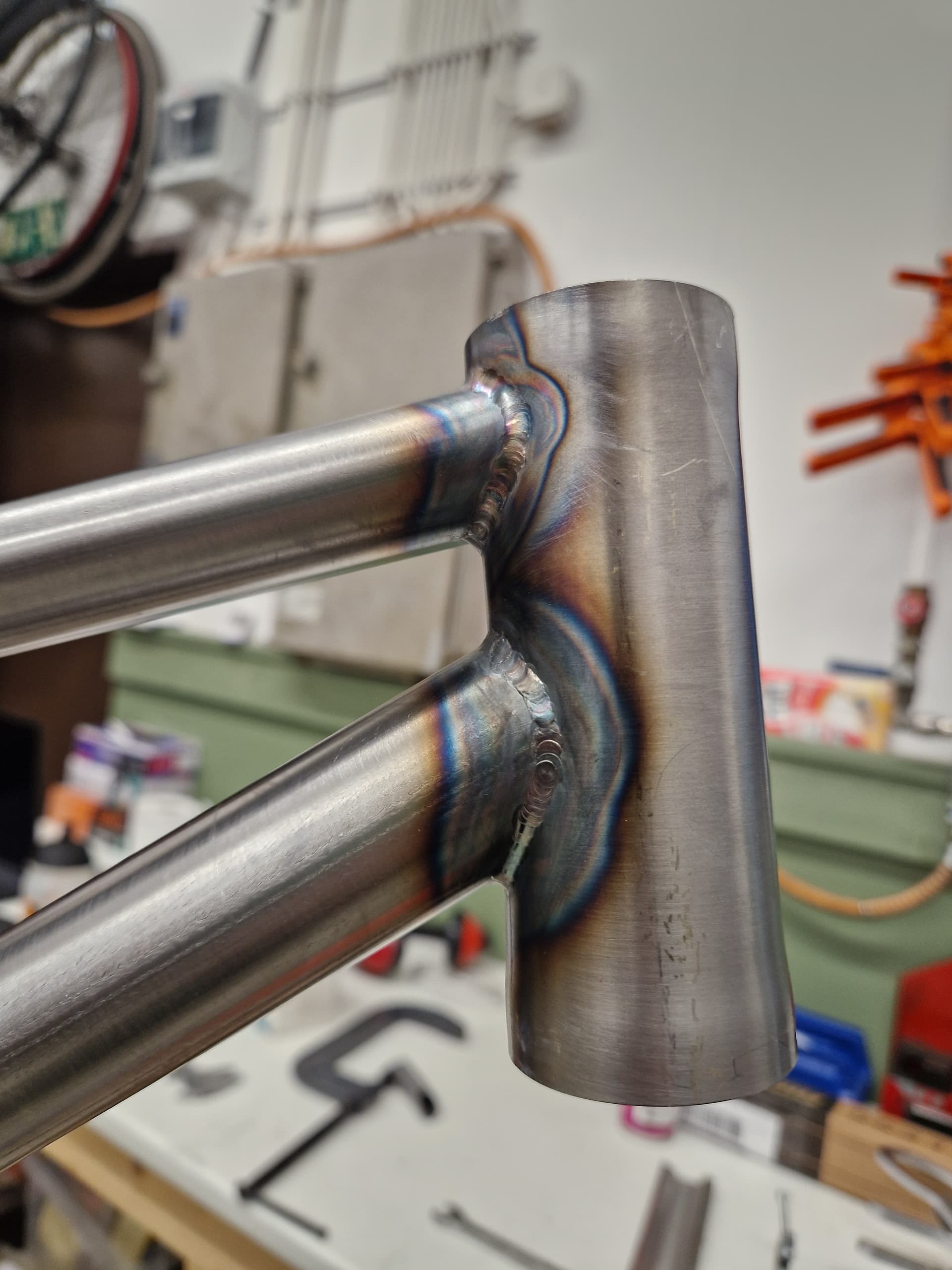
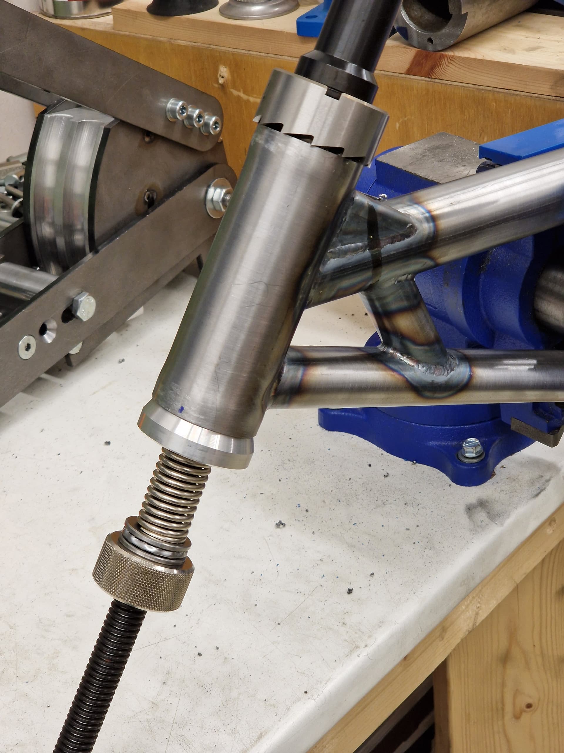
Headtube 45 x 1,5 (ends stretched with mandrel to 44 id)

Chainstays: 19,05 x 0,89 (front ends ovalized)

Seatstays: 15,88 x 0,89

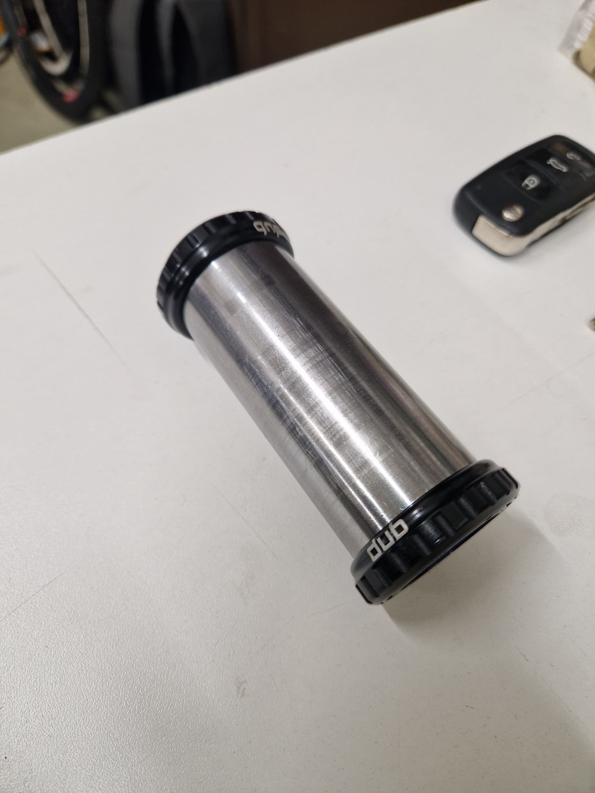
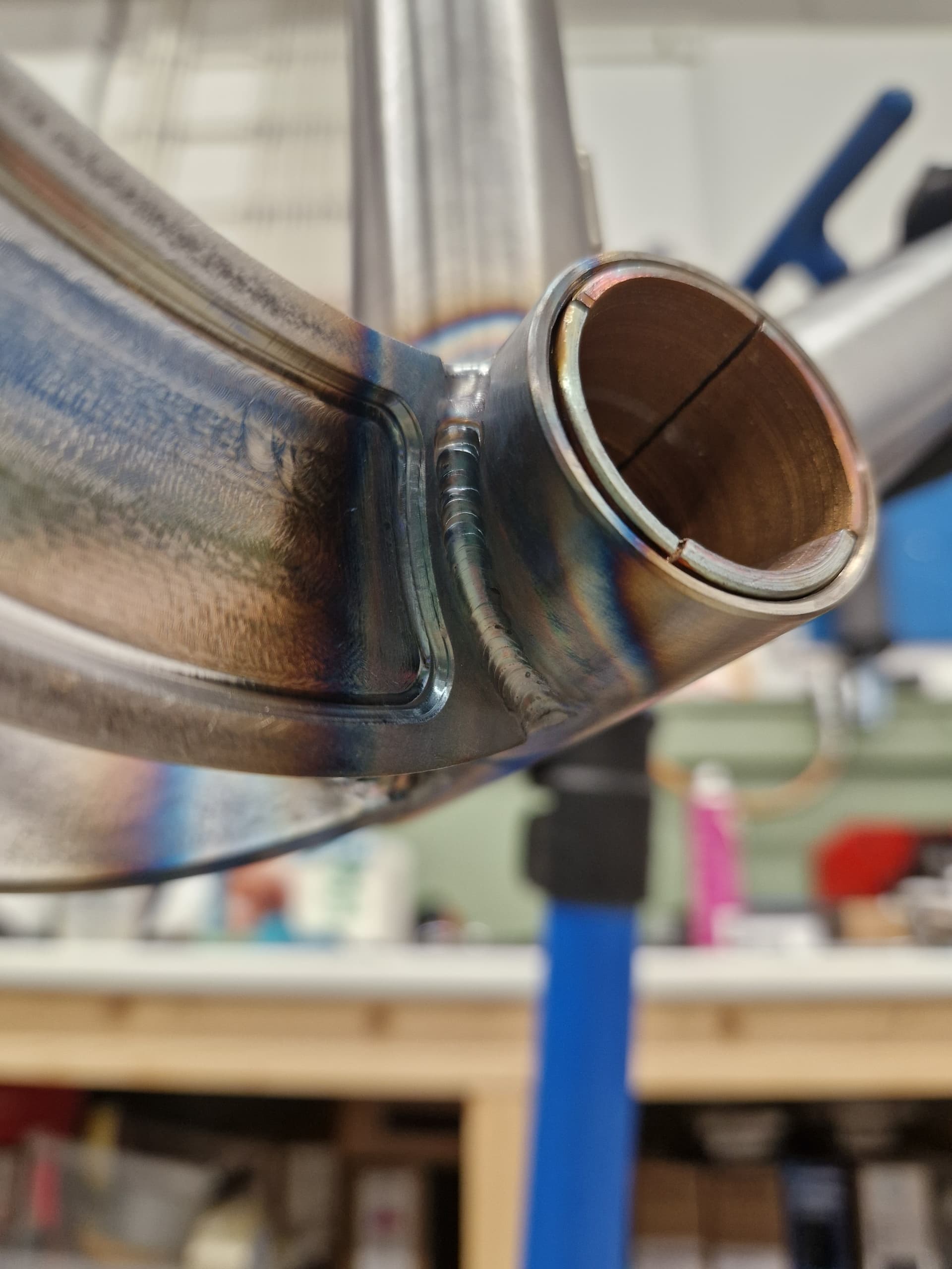
BB: 38,1 x 2,11

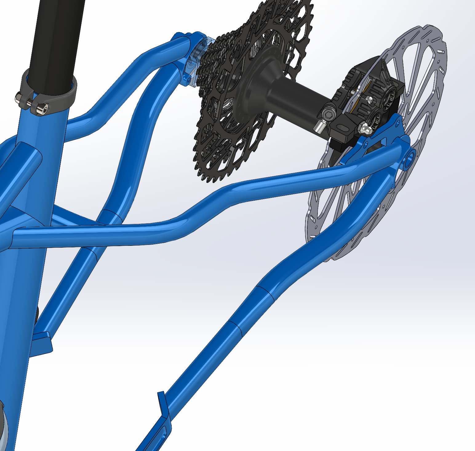
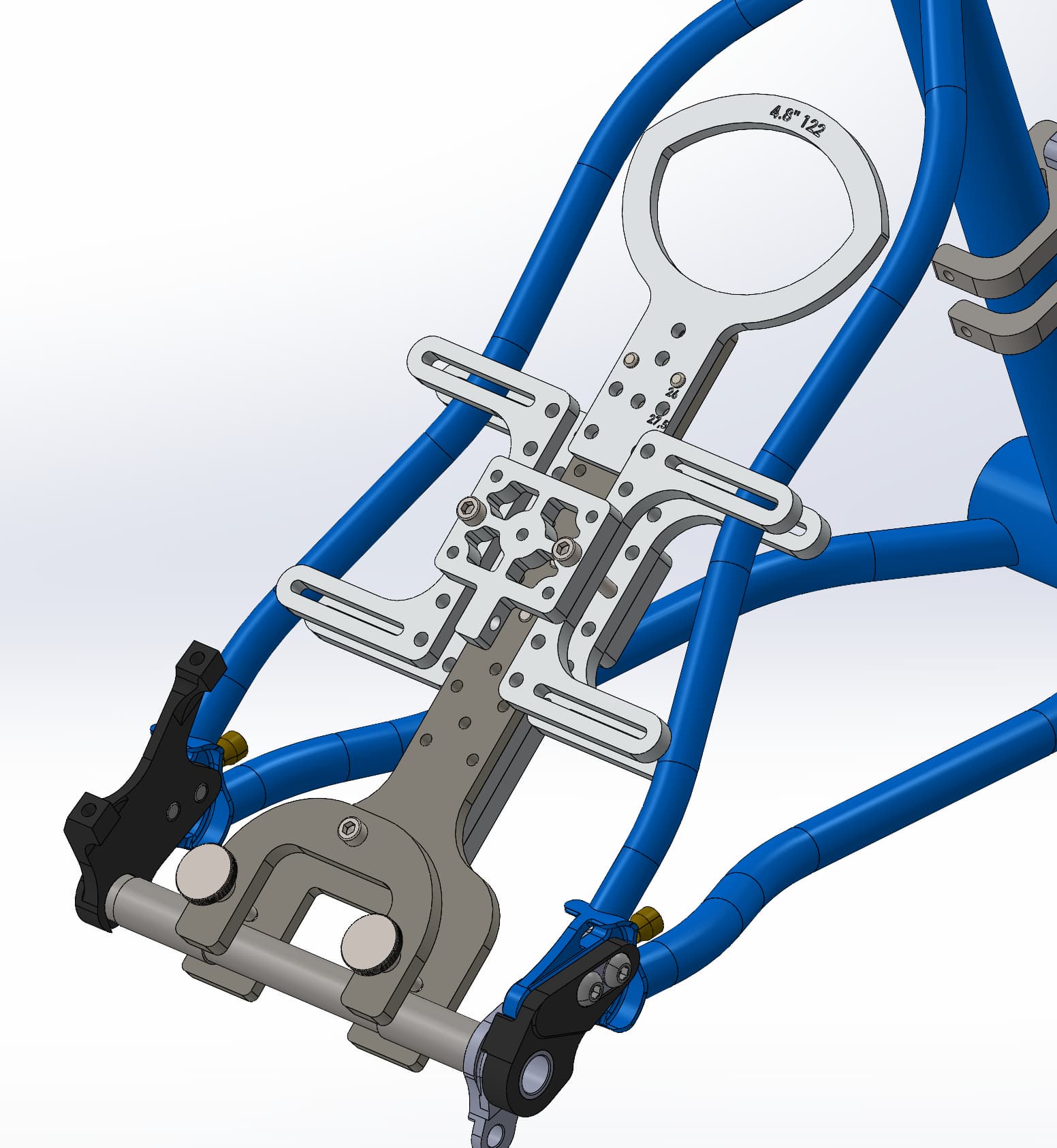
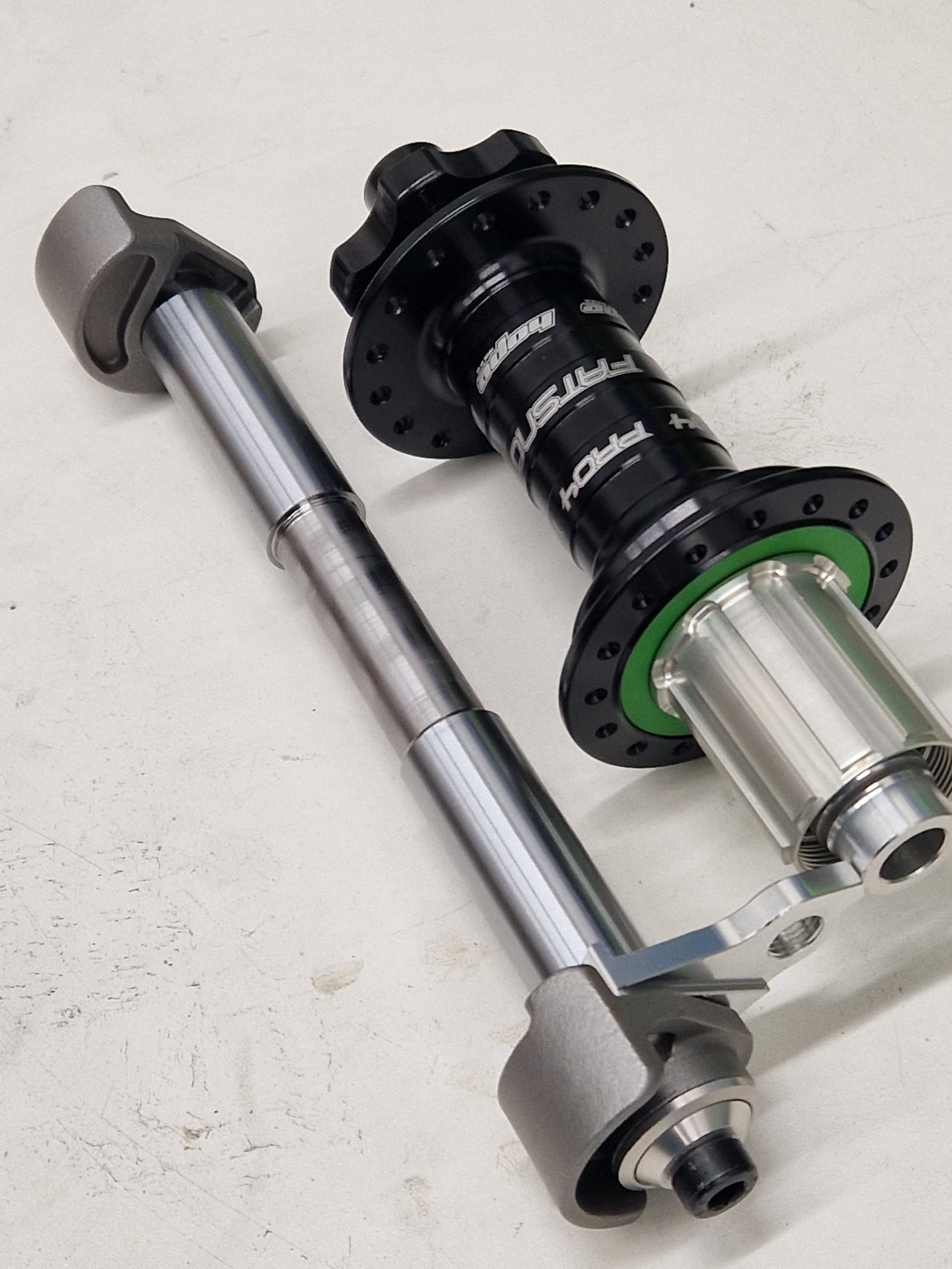
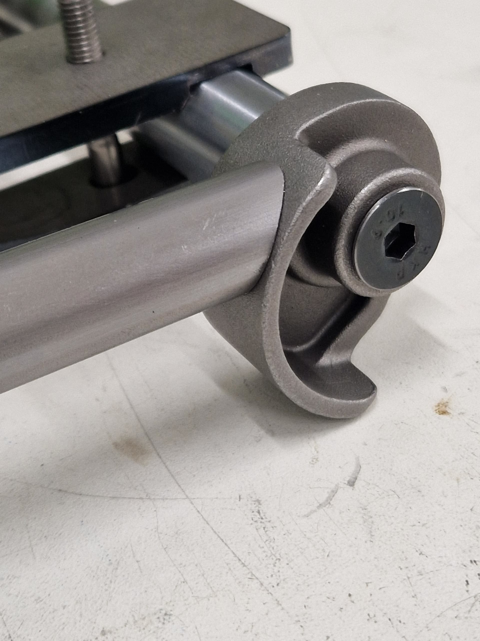
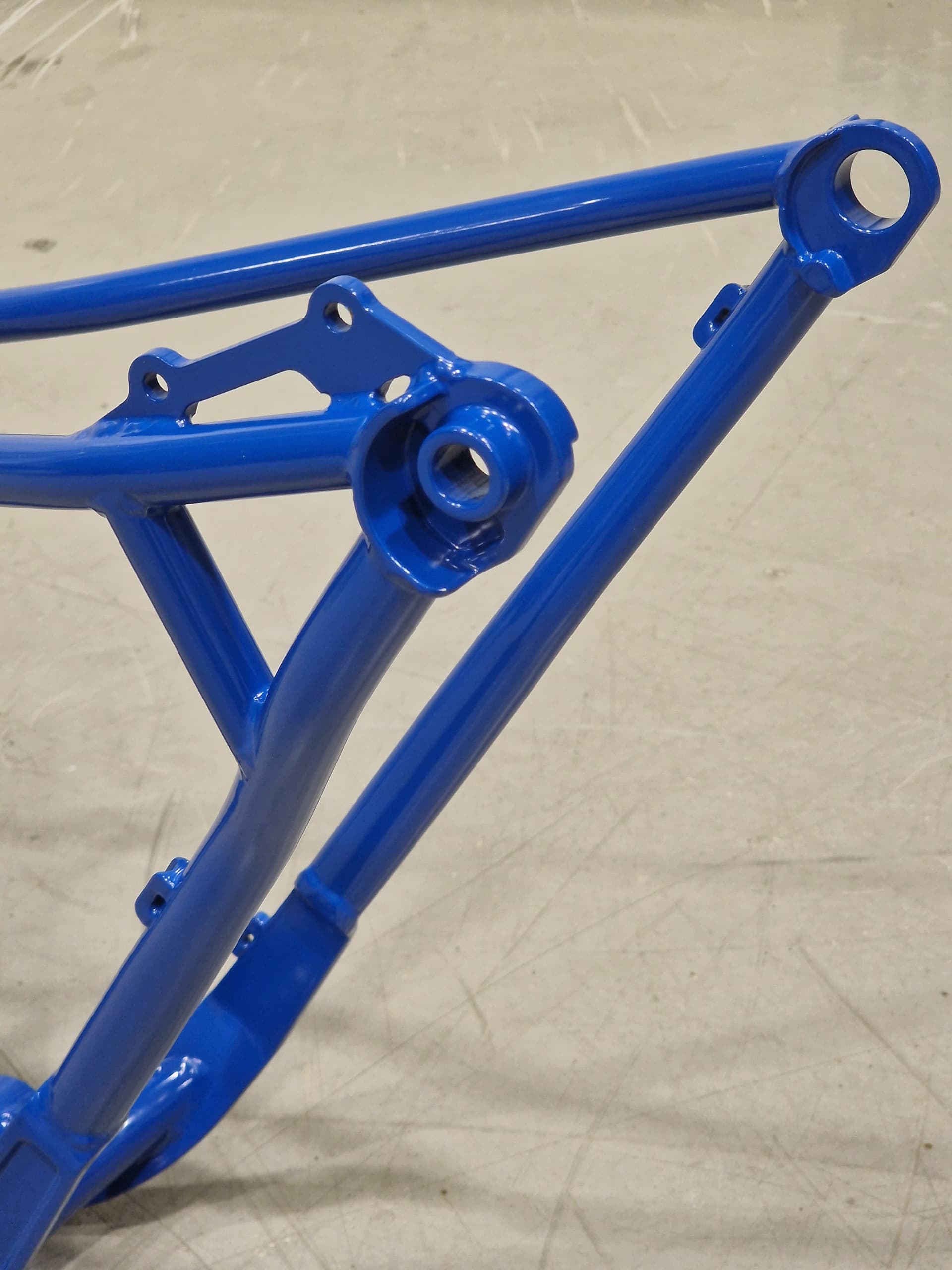
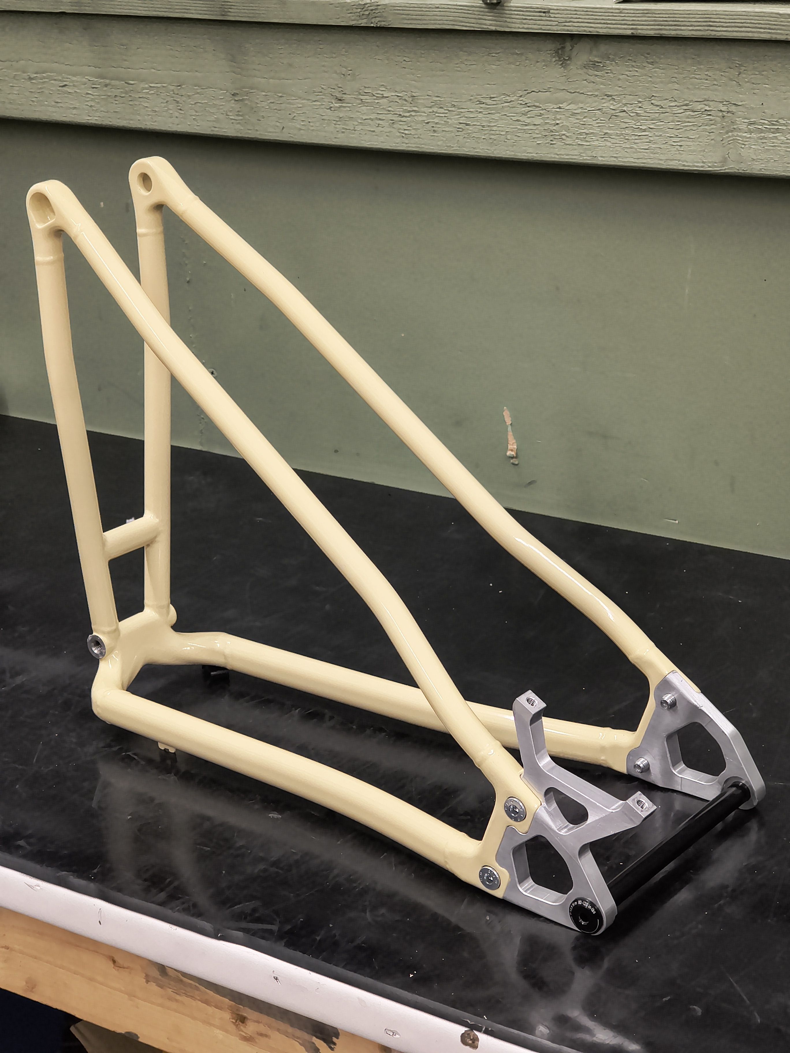
Dropouts are cast steel UDH from Framebuilder Supply.


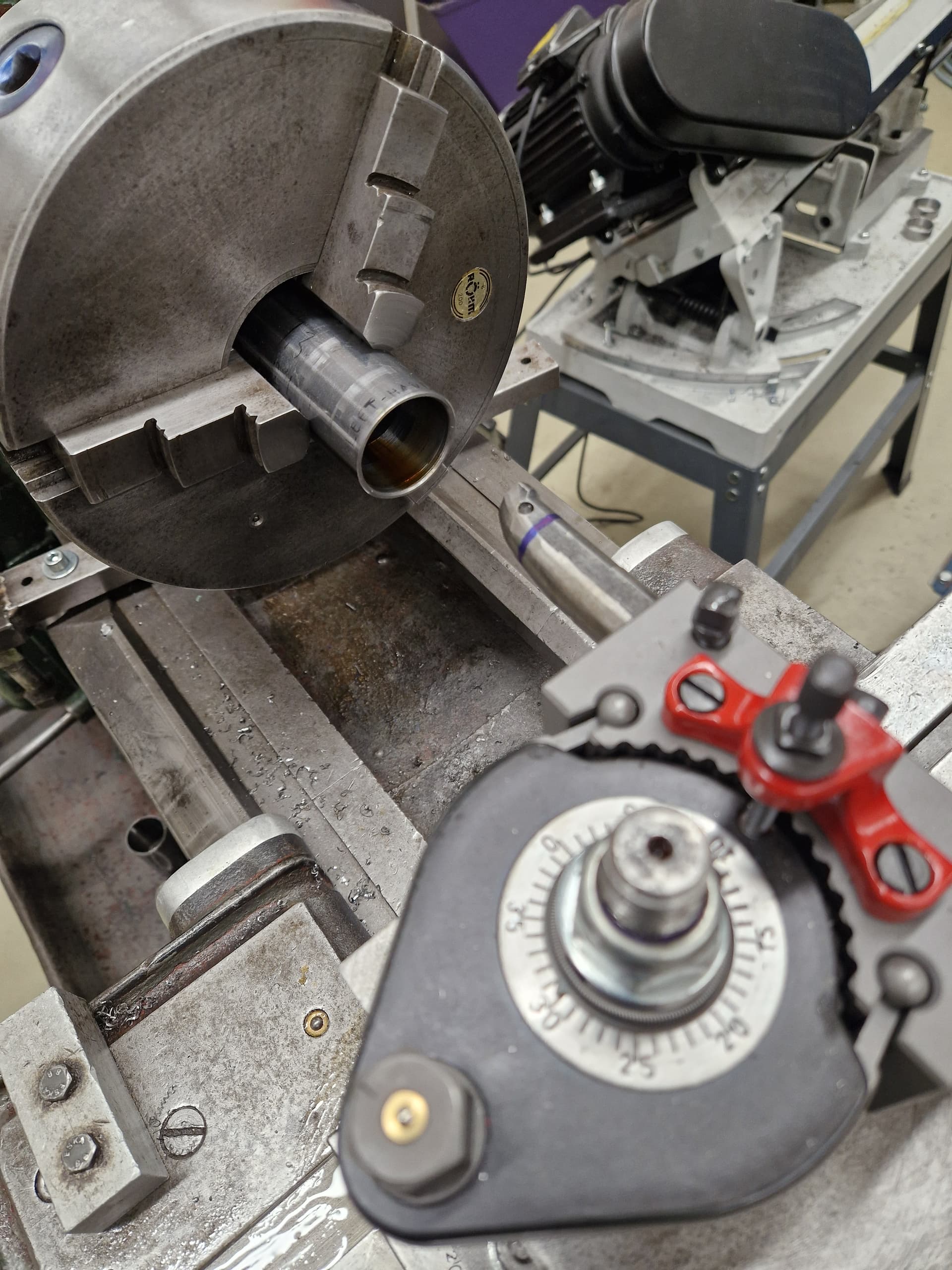
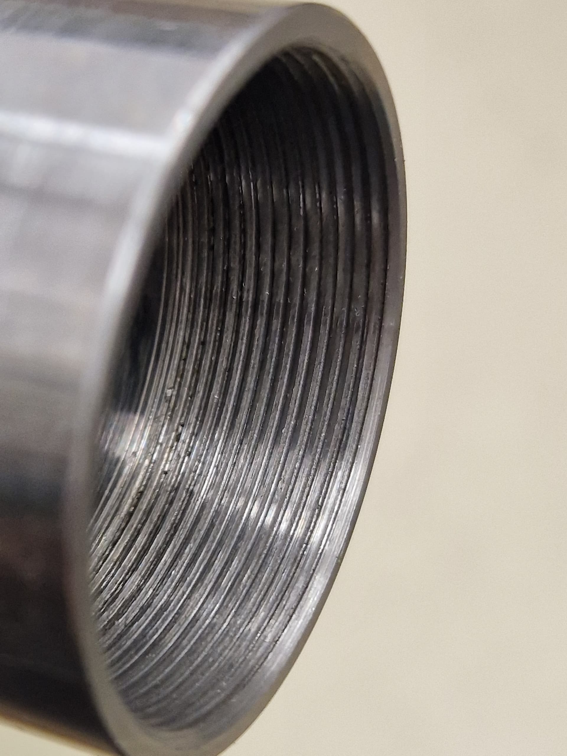
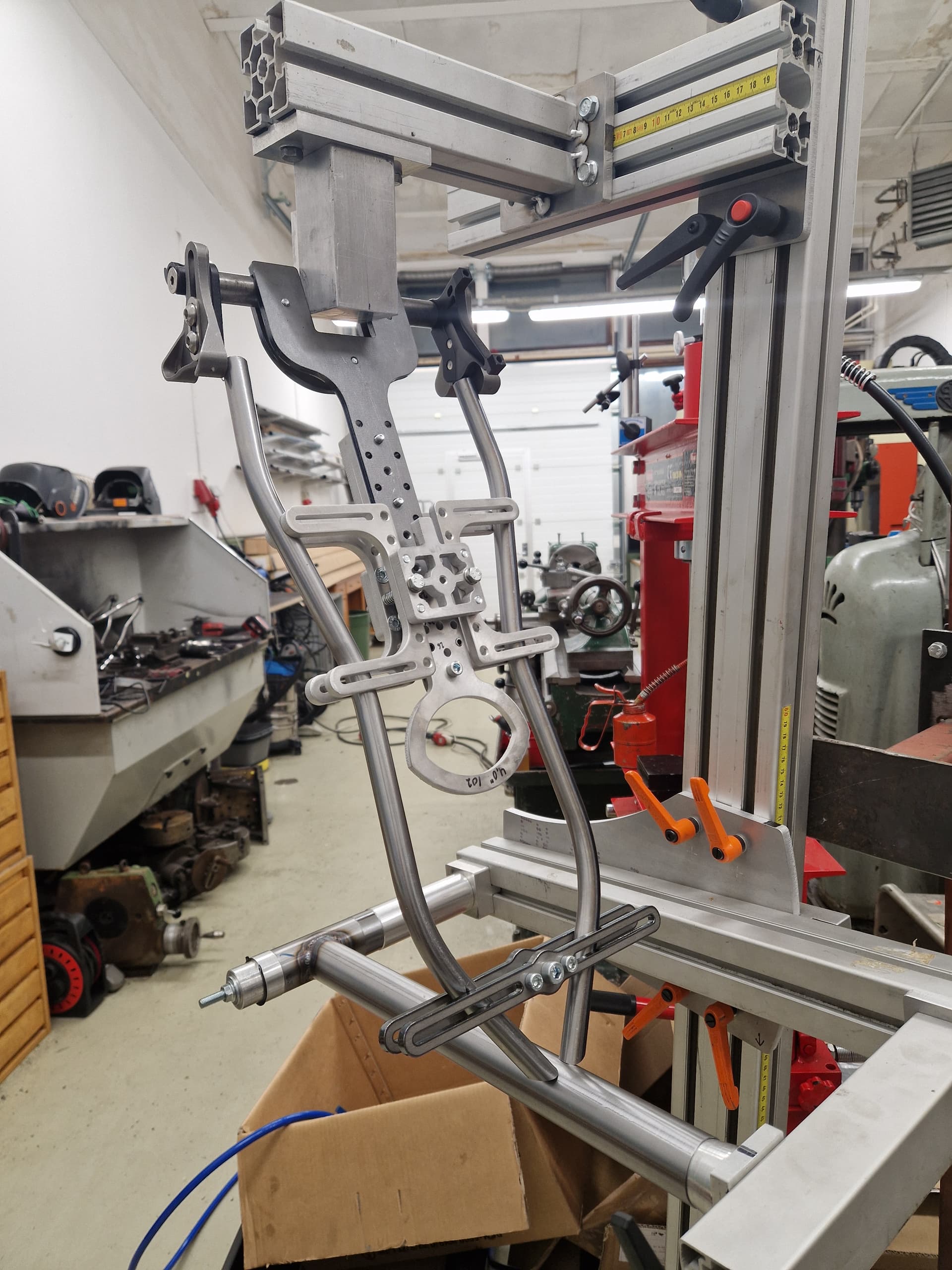
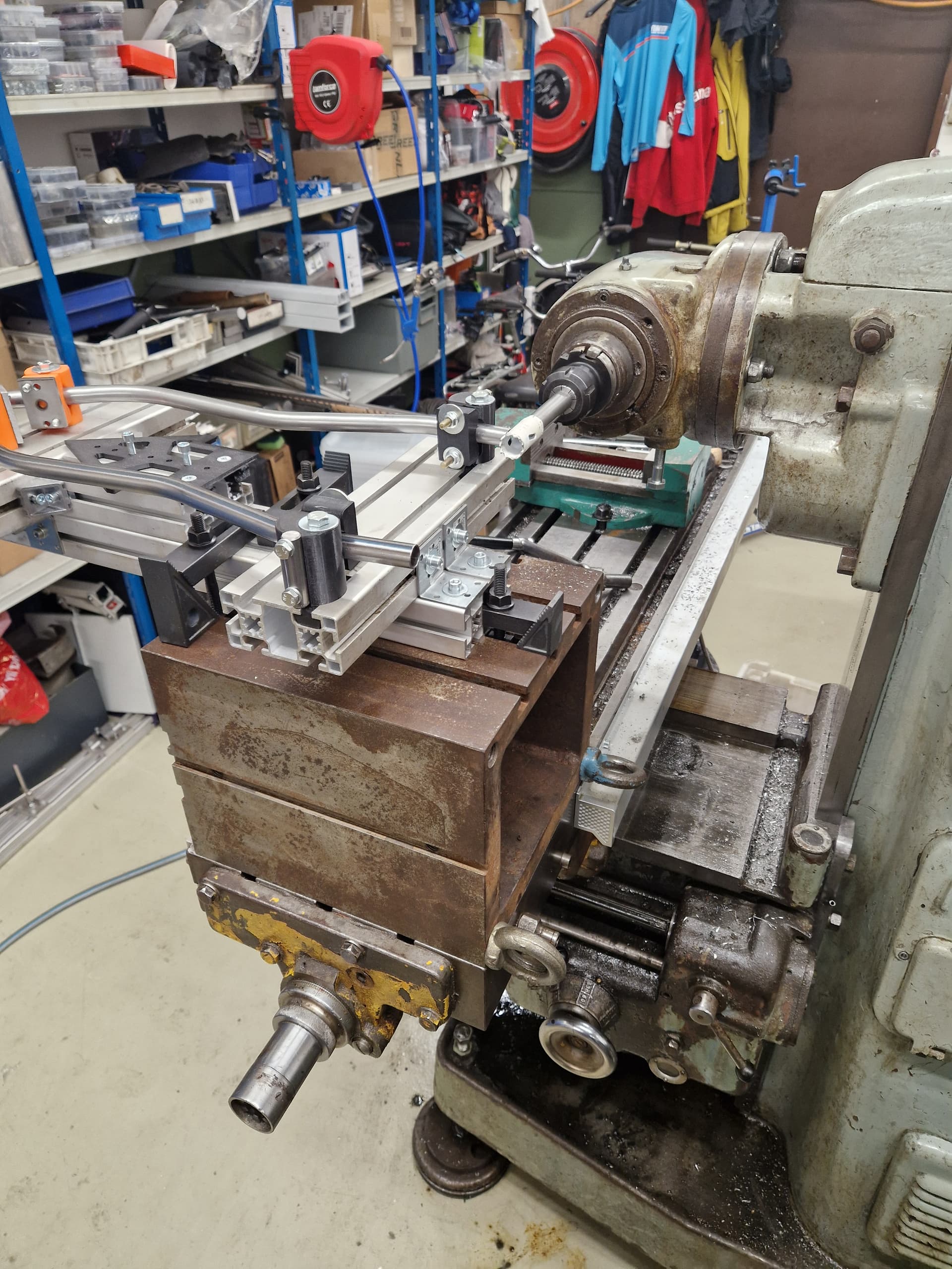
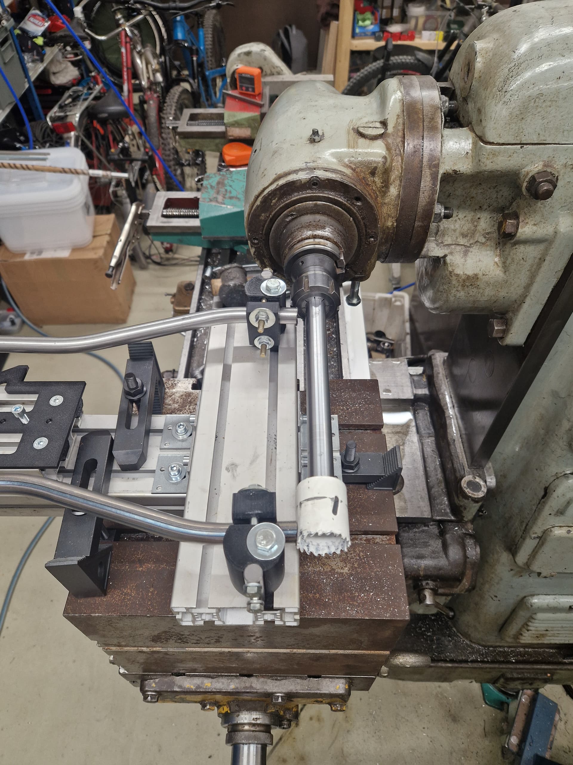
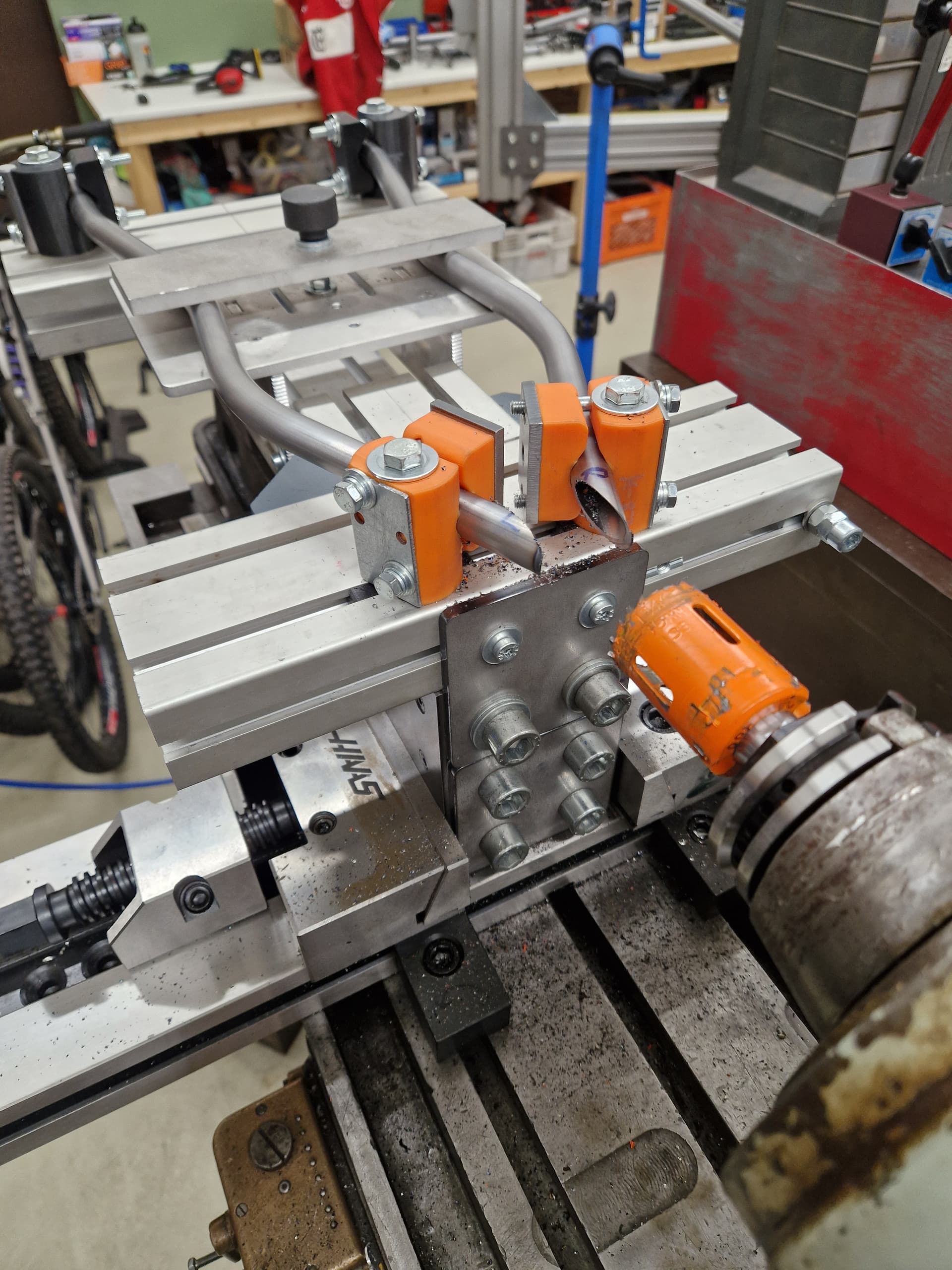
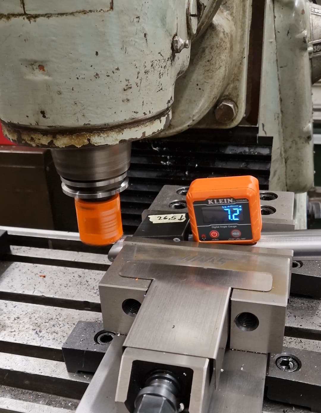
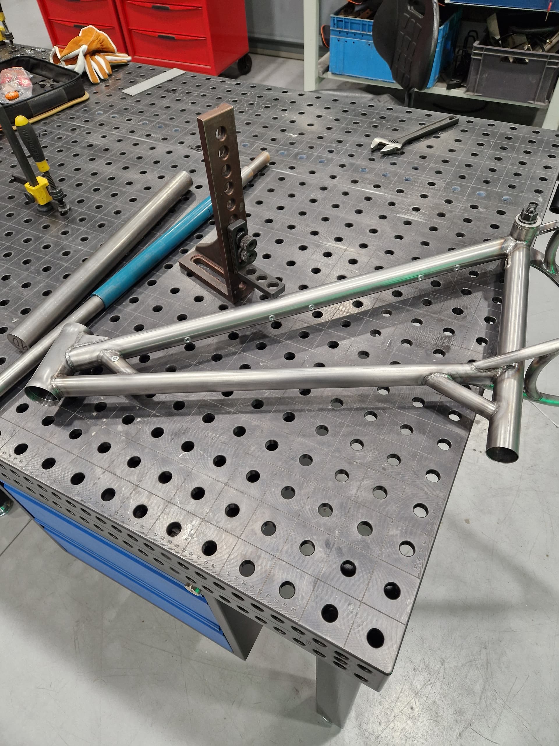
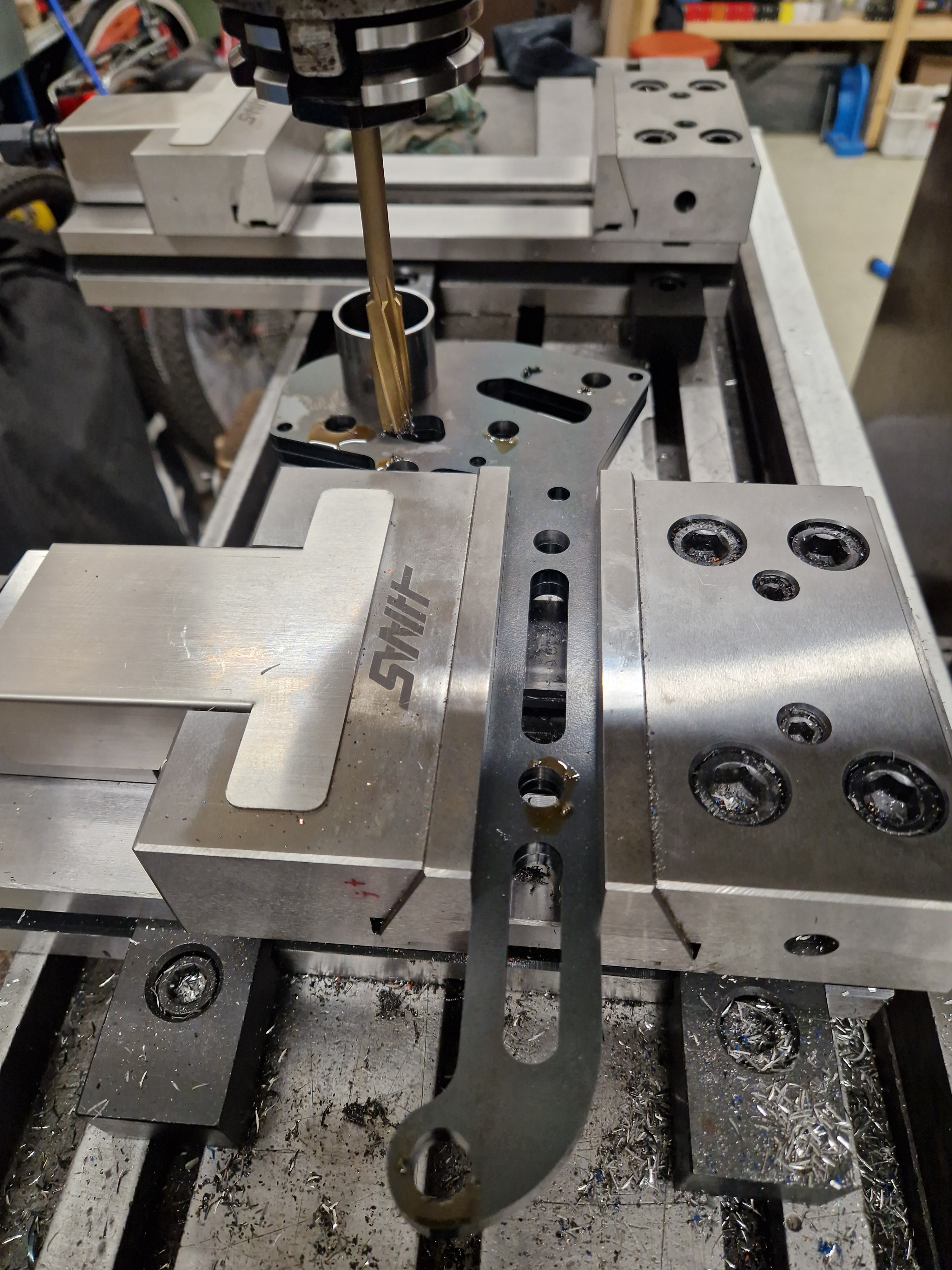
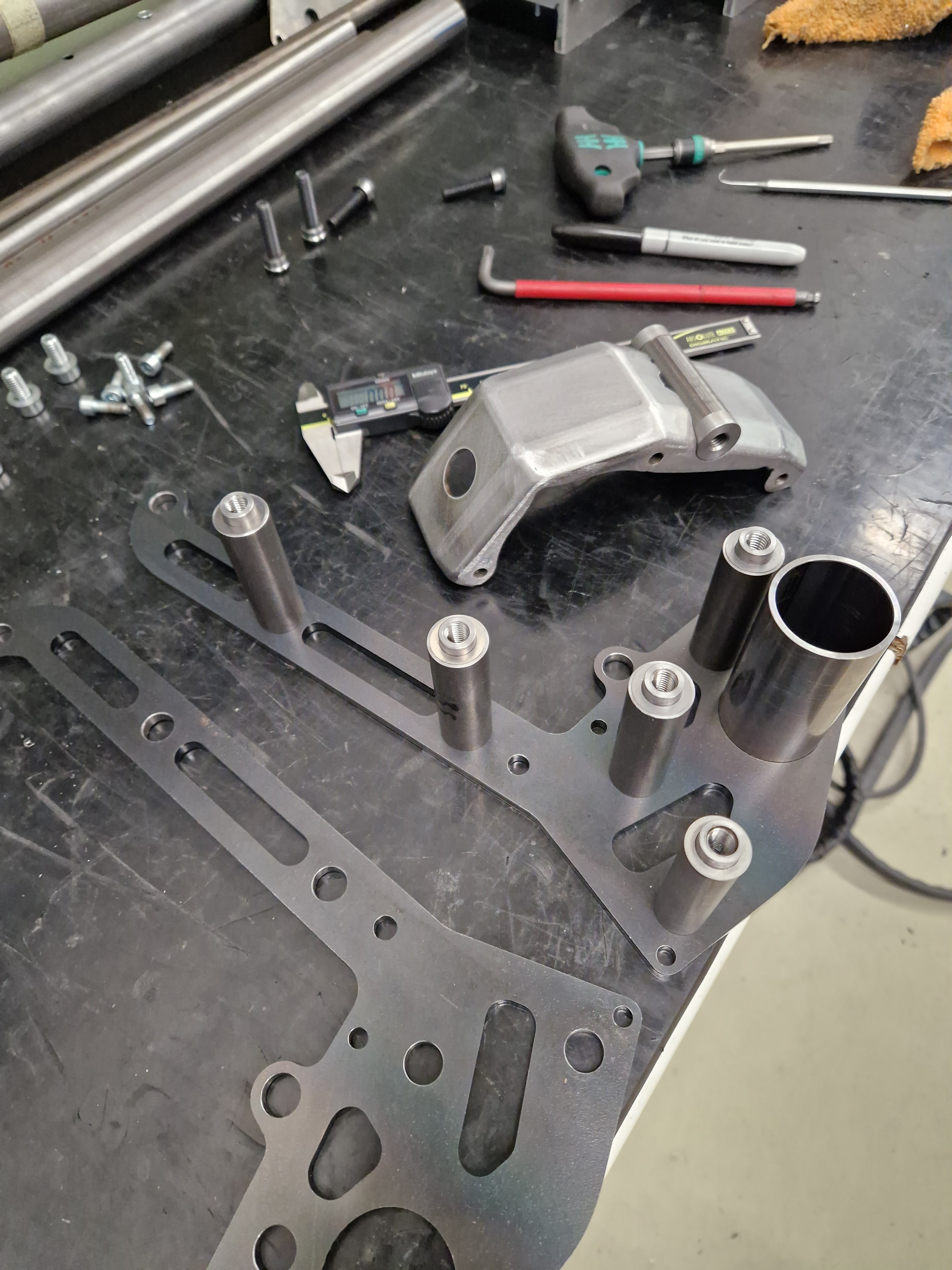
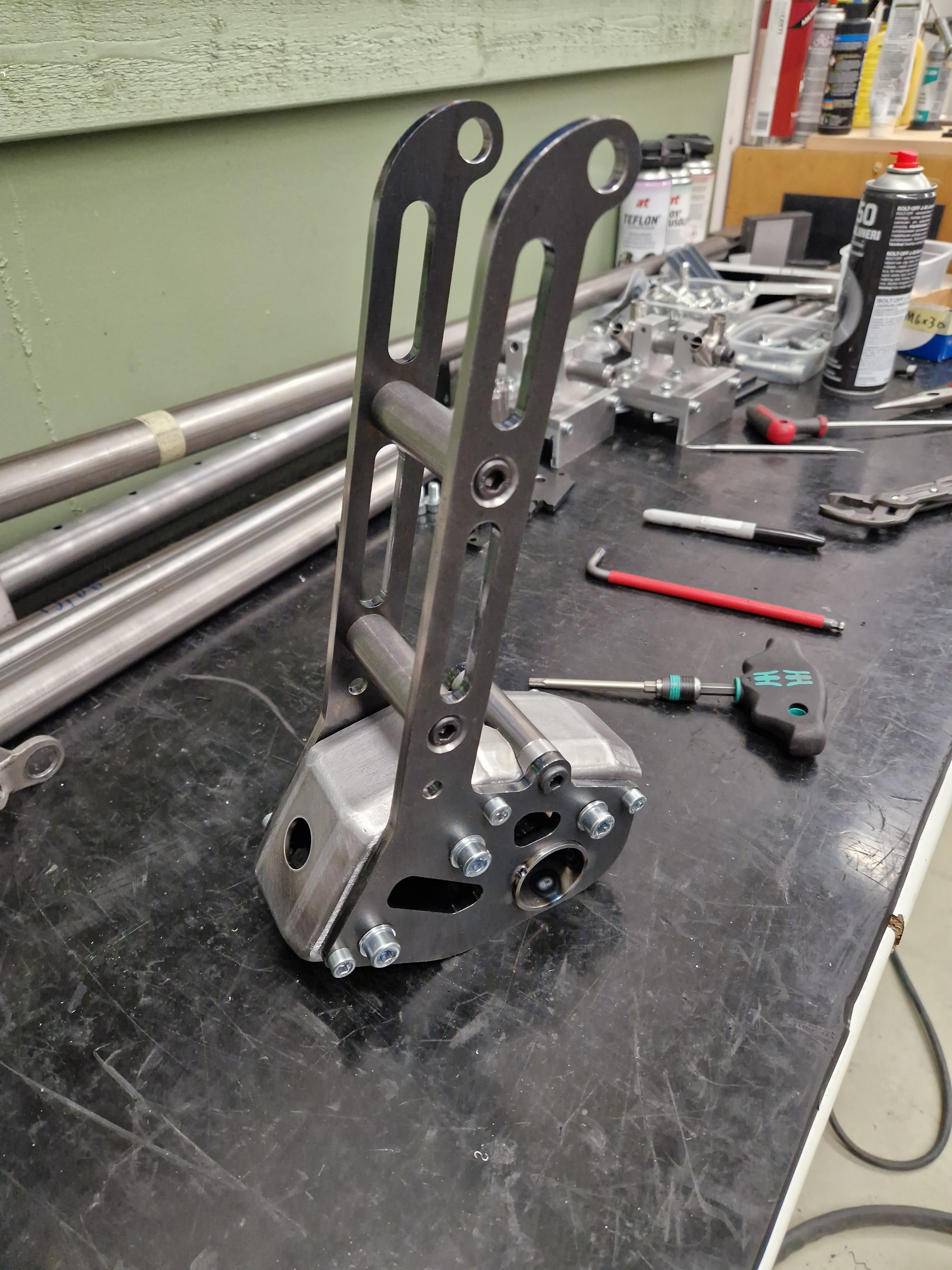
We rented a shop with Olli during the time, and I also bought a manual lathe and milling machine. So a lot of time was spent on setting up the shop and machines, and also repairing them. And learning to use the machines, since my experience with actual machining is close to zero. And of course, the framebuilders favourite, designing and building tools :smiley:

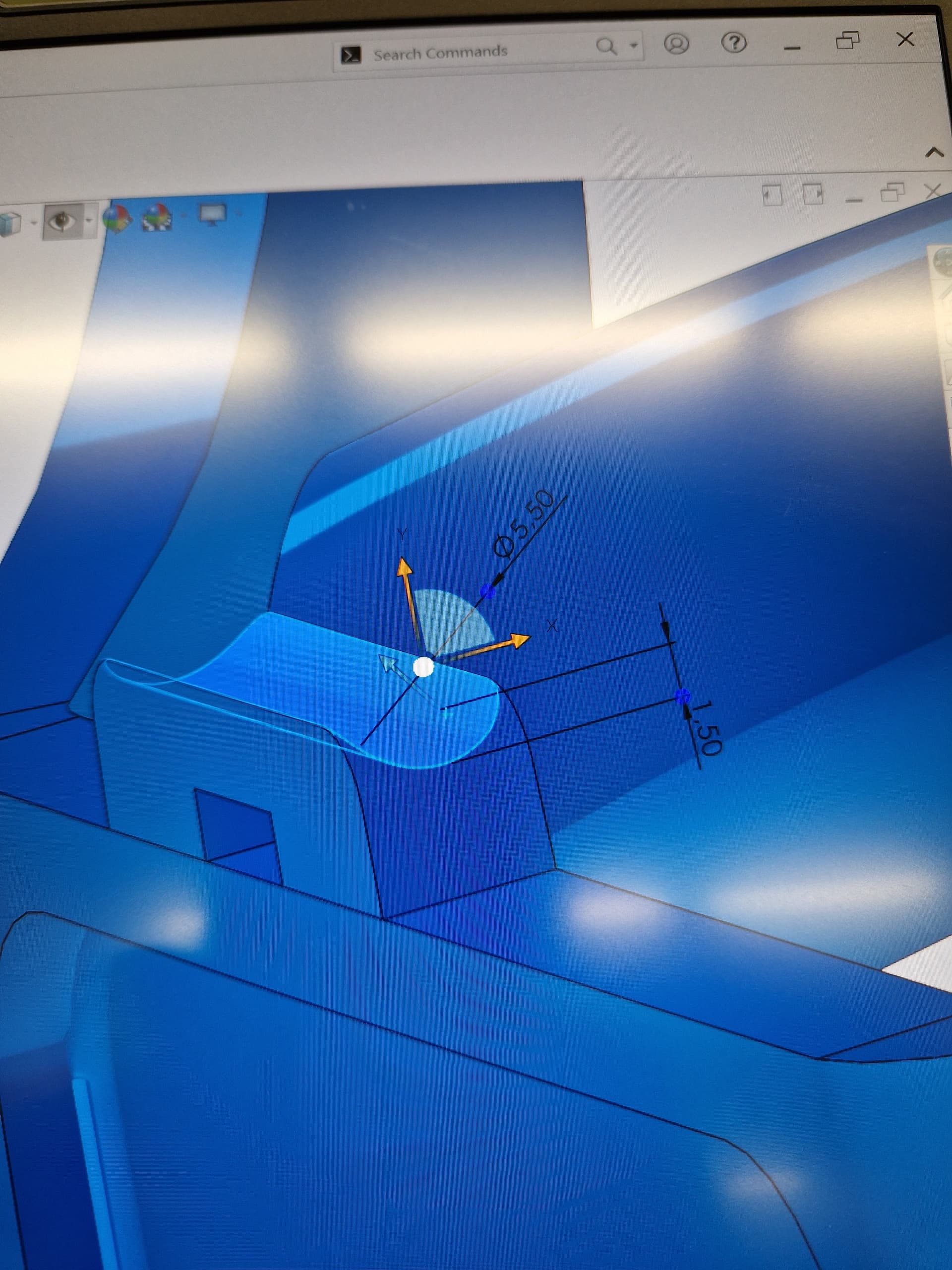
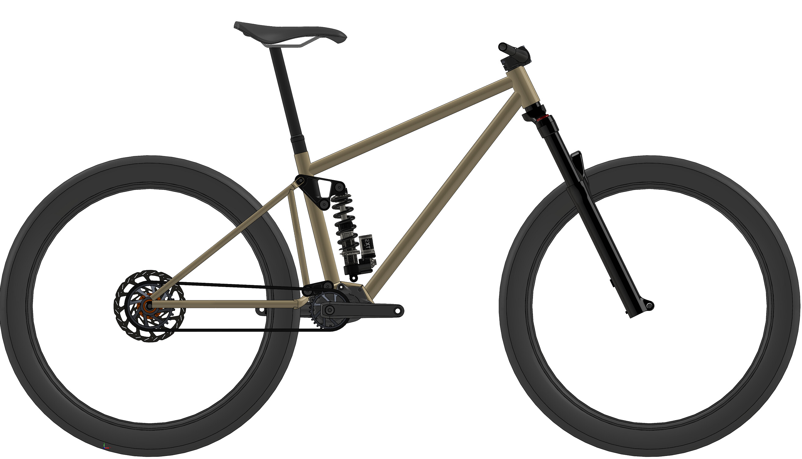
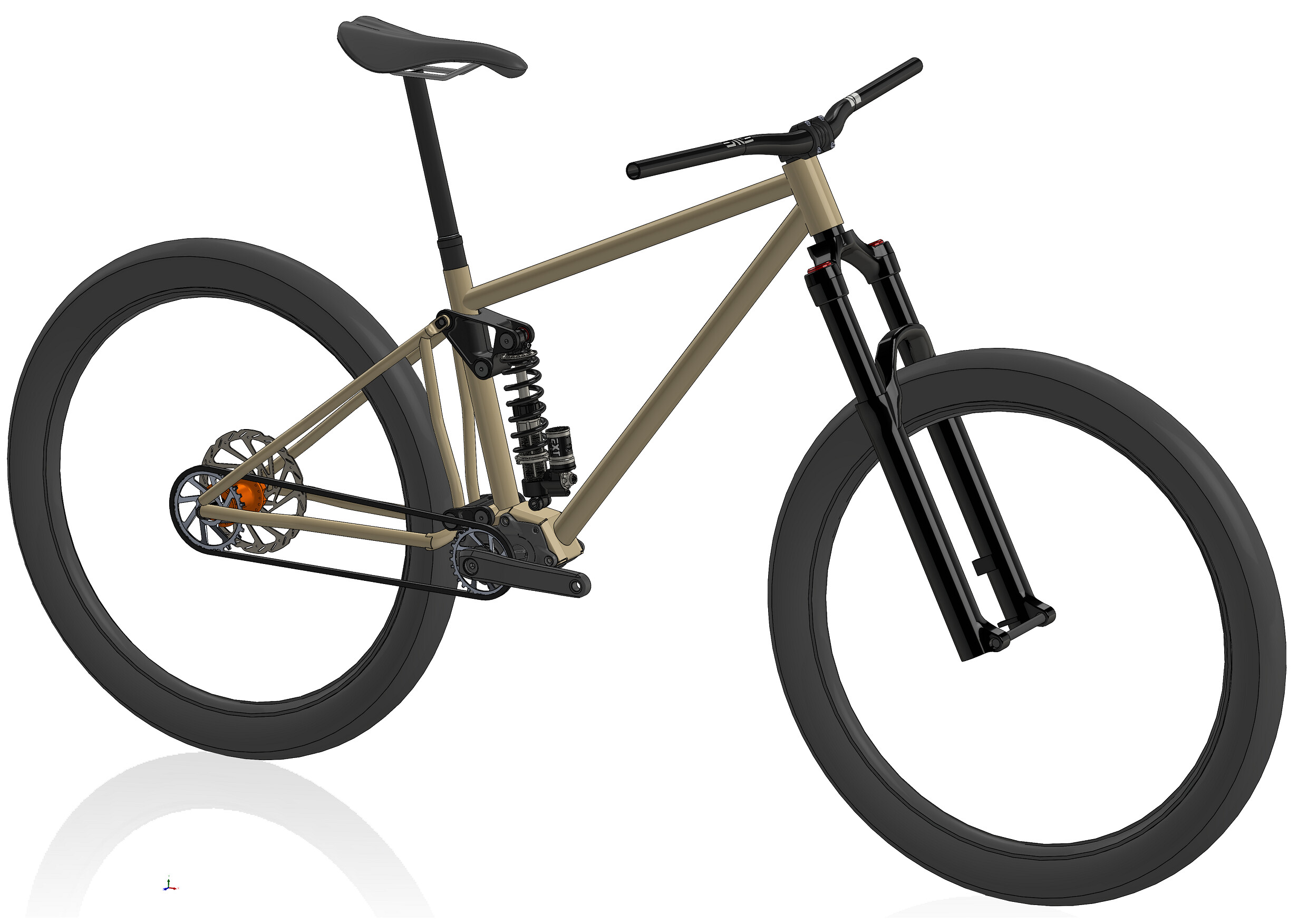
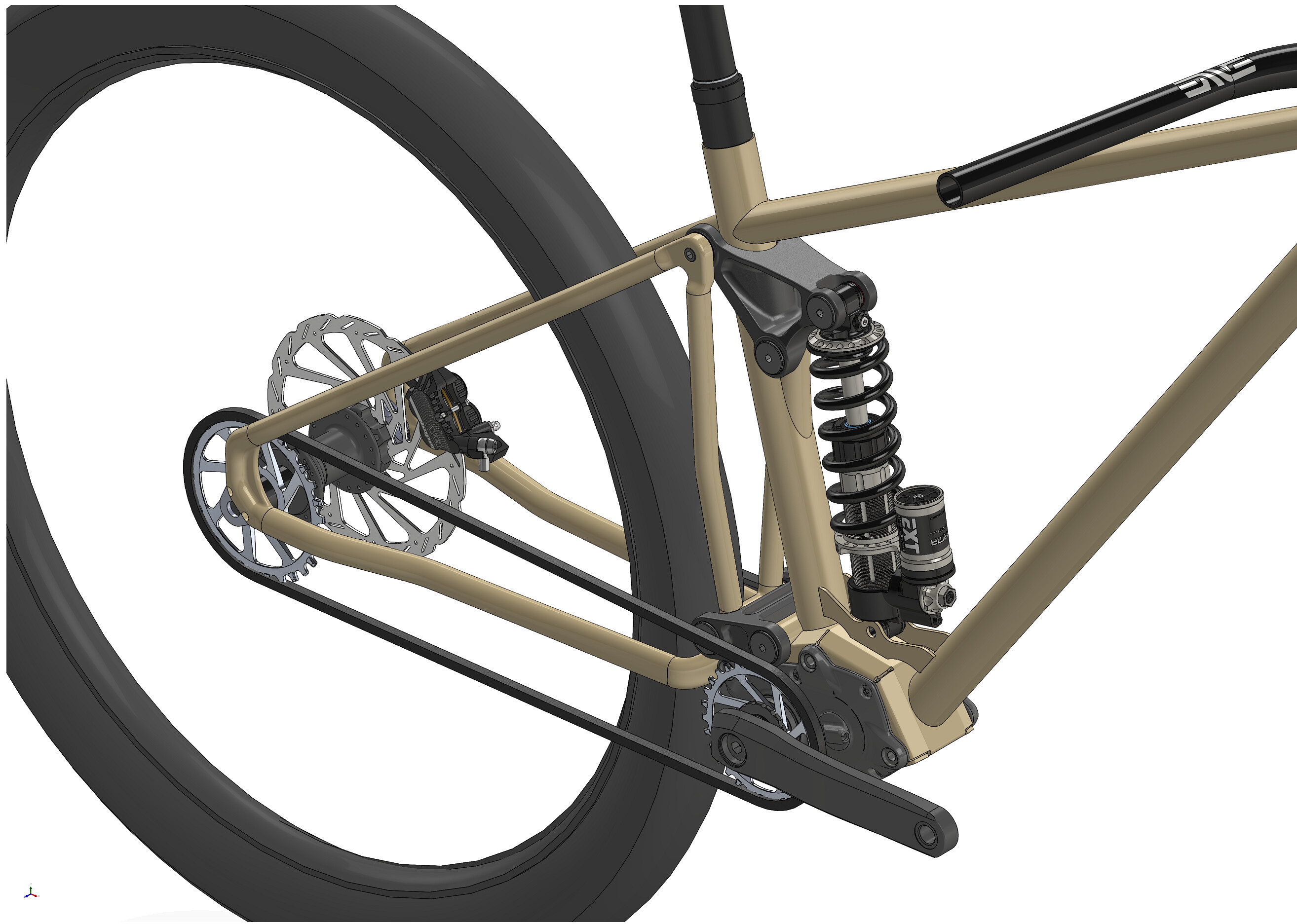
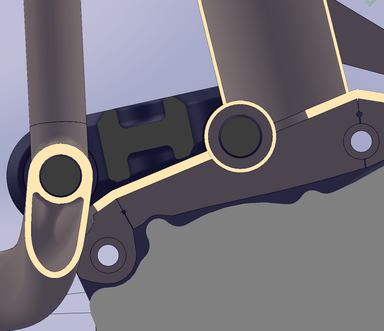
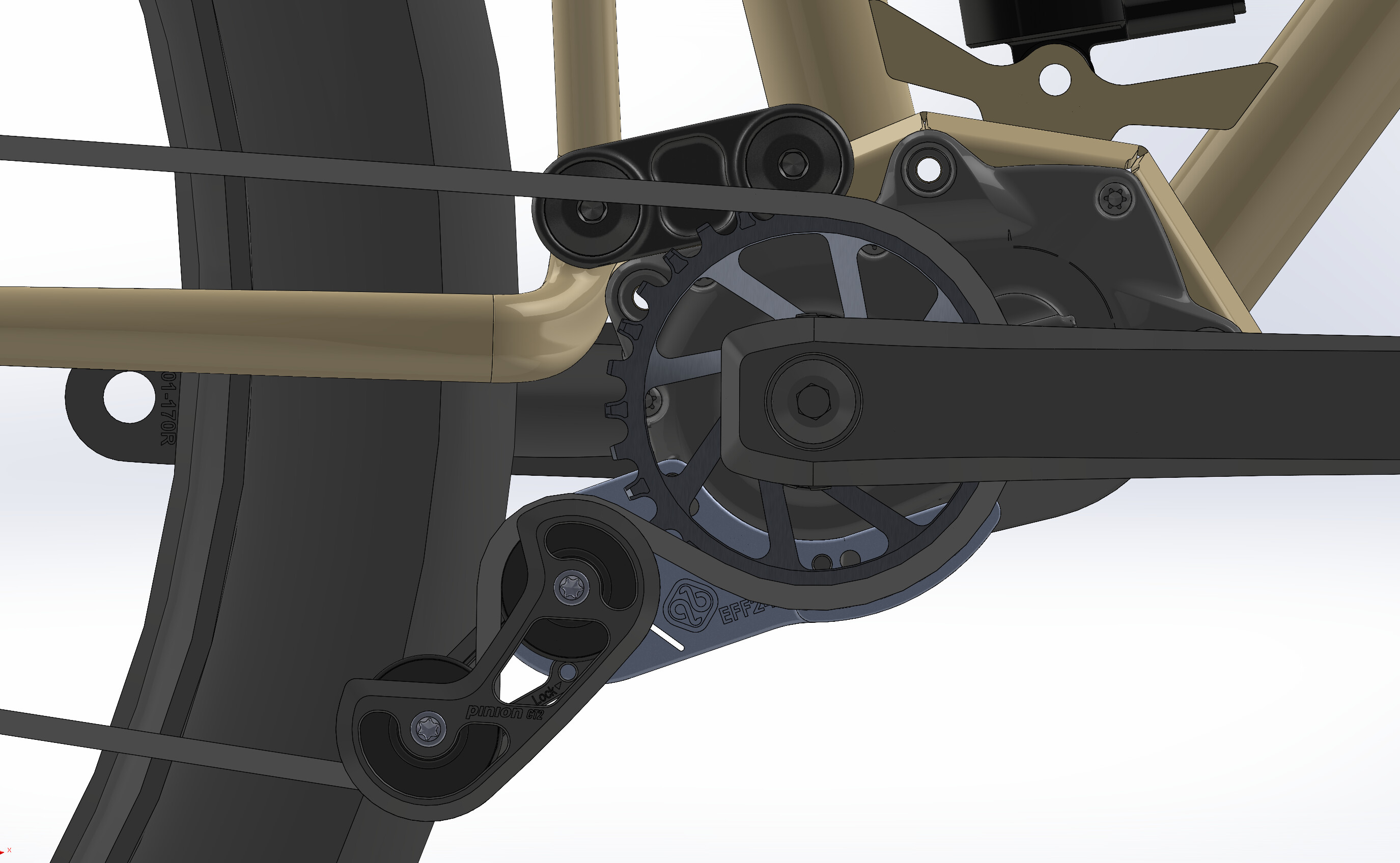
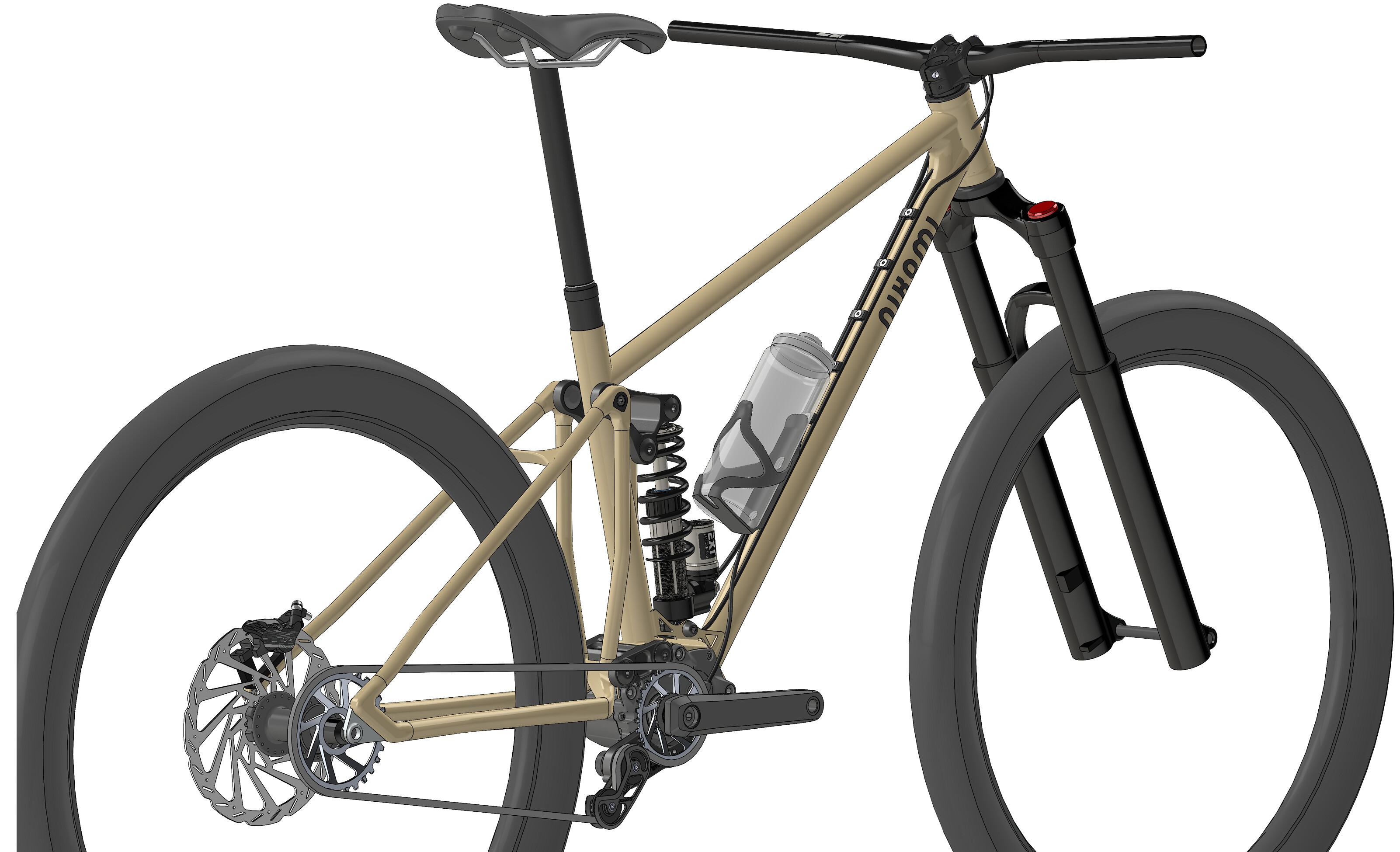
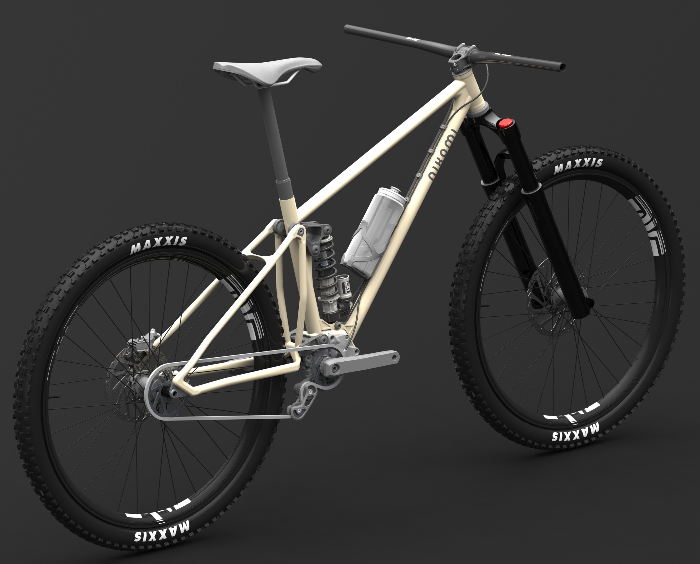
Few pictures from SolidWorks:

To be continued…

4 Likes

Happy New Year 2026! I hope you all make lots of good bikes this year :blush:

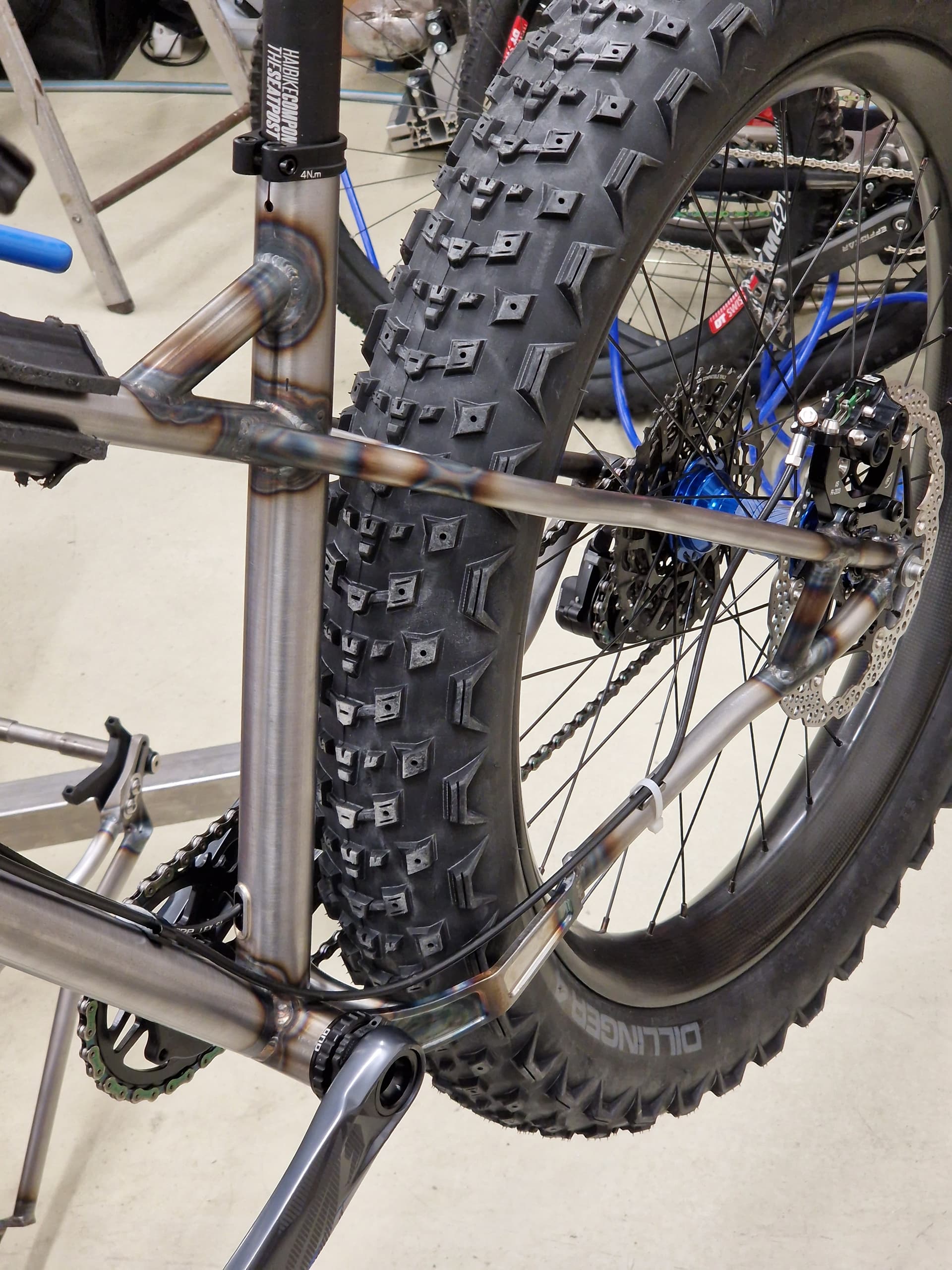
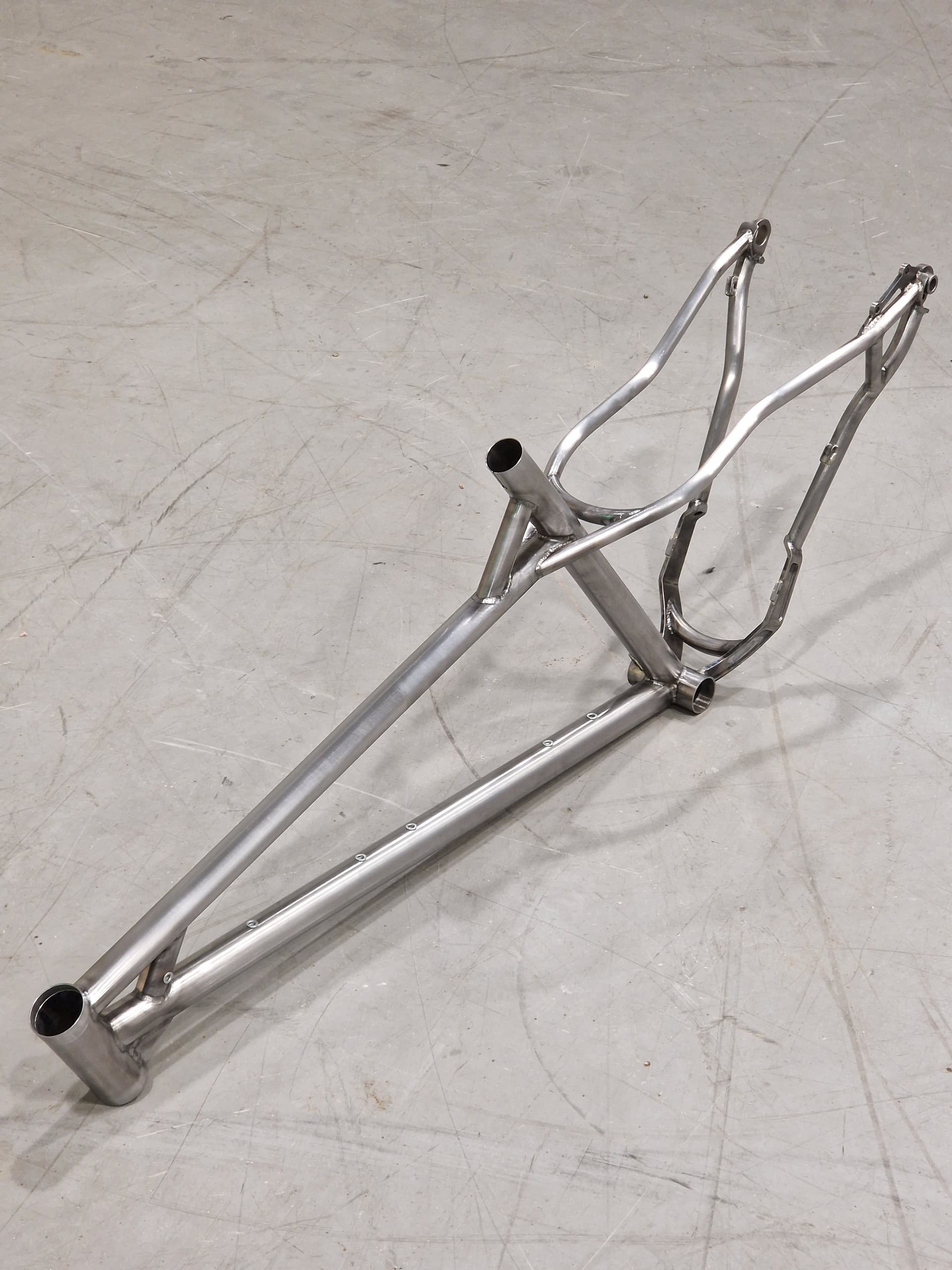
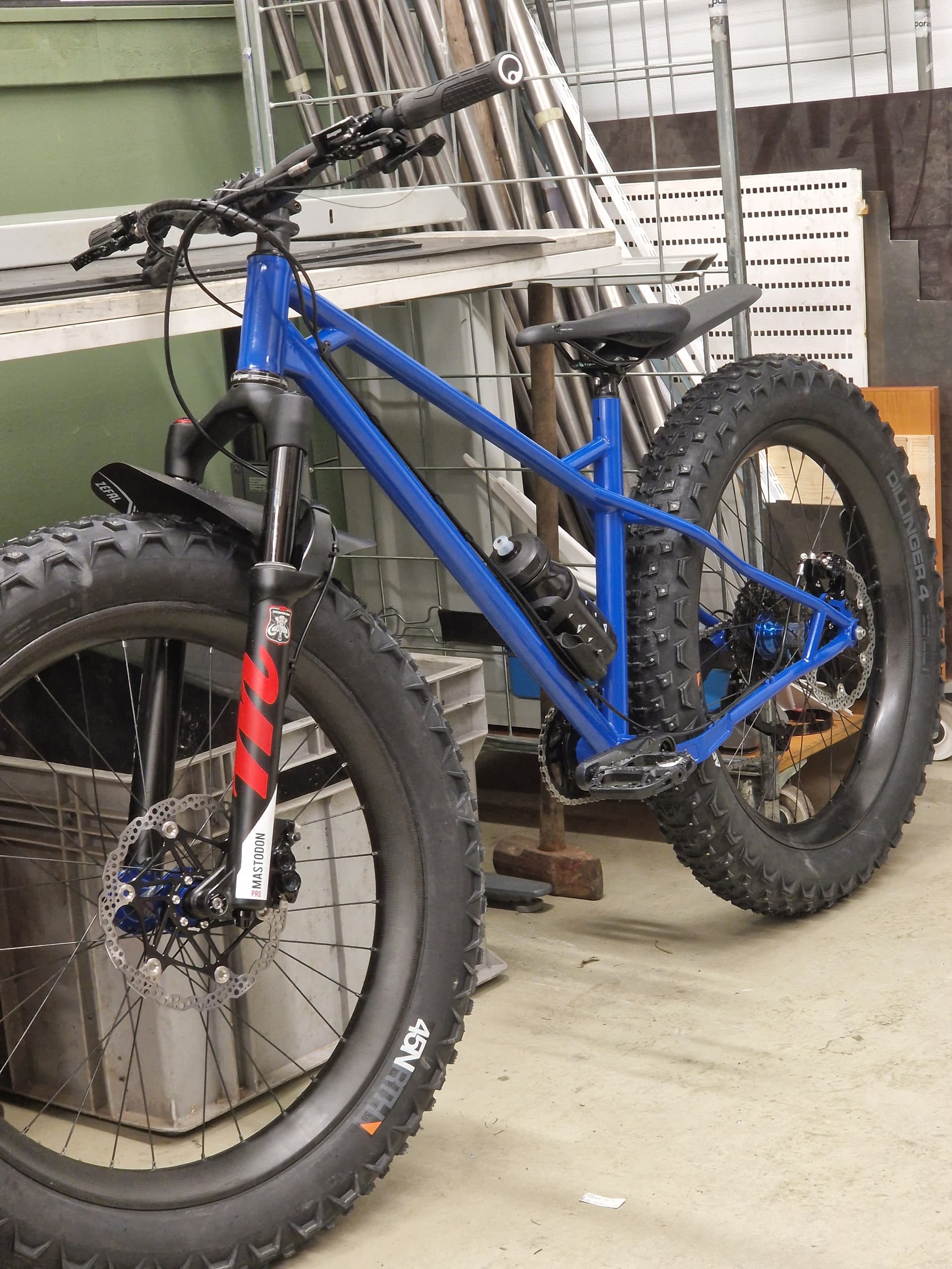
Here is a photodump of the Pulska. Please ask if any questions come to mind!!

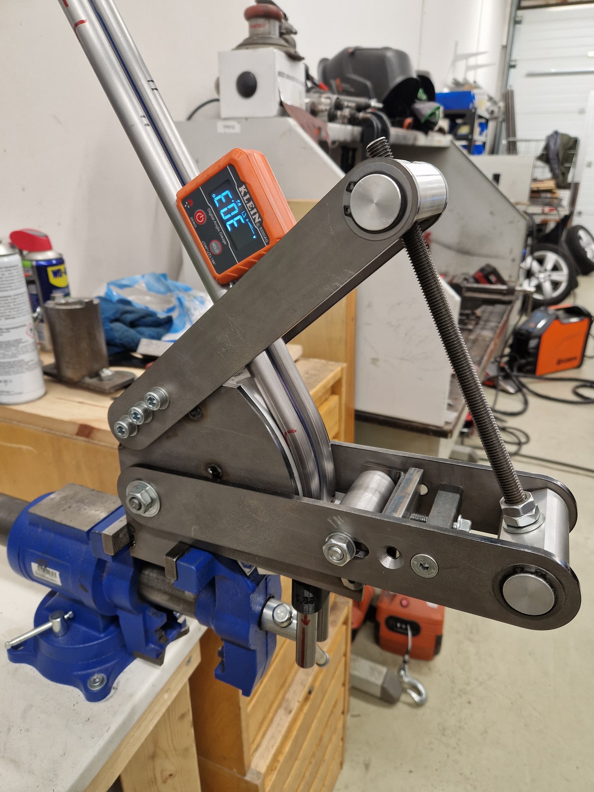
As you can see, I like the tool building also. Most of the stuff here is purely for prototyping and testing the ideas of the tools. Well, the tube bender has seen a lot of use,and you know what they say, “Imitation is the sincerest form of flattery”. In that case there must be a certain Joe who is most certainly flattered :smiley:


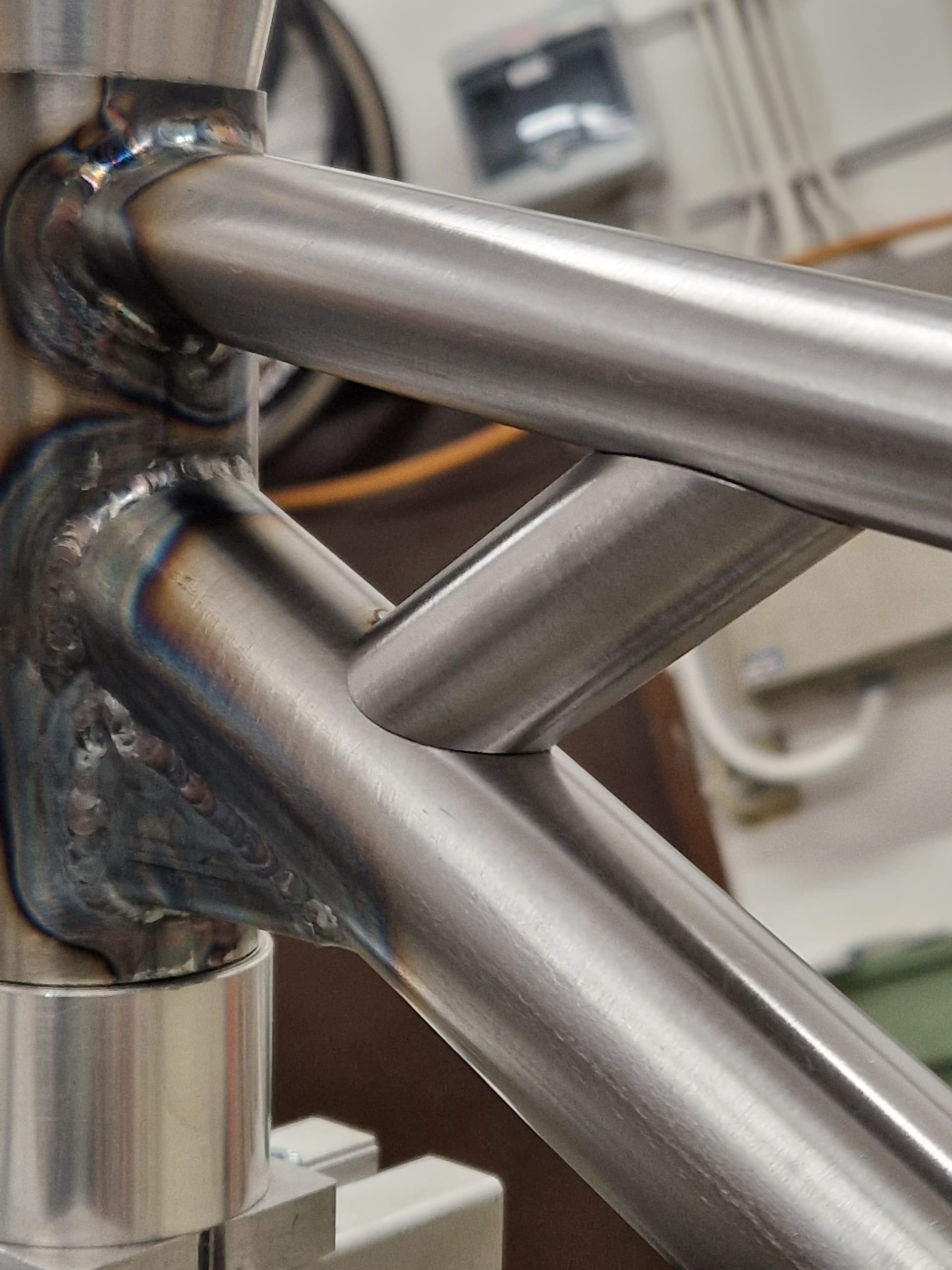
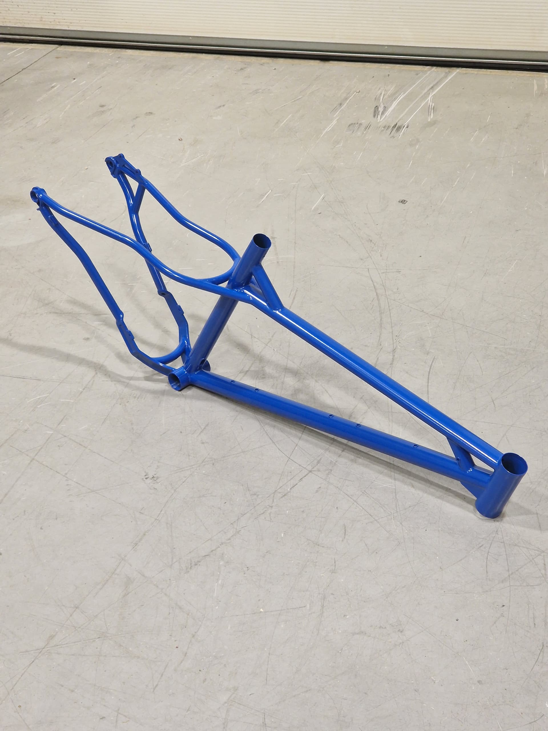
Here is how the design actually ended up, with different gusseting for the headtube to allow space for the Mastodon fork.

Geometry with Mastodon 120mm @ 20% SAG

HTA: 67

STA: 77

Reach: 460

Stack: 625

Chainstay: 445

BB drop: 45

13 Likes

LOVE this bender!! It looks similar to mine, but like you seriously improved just about every aspect of it. Really nice work throughout!

4 Likes

Simply superb from start to finish!

1 Like

Thanks for the comments!

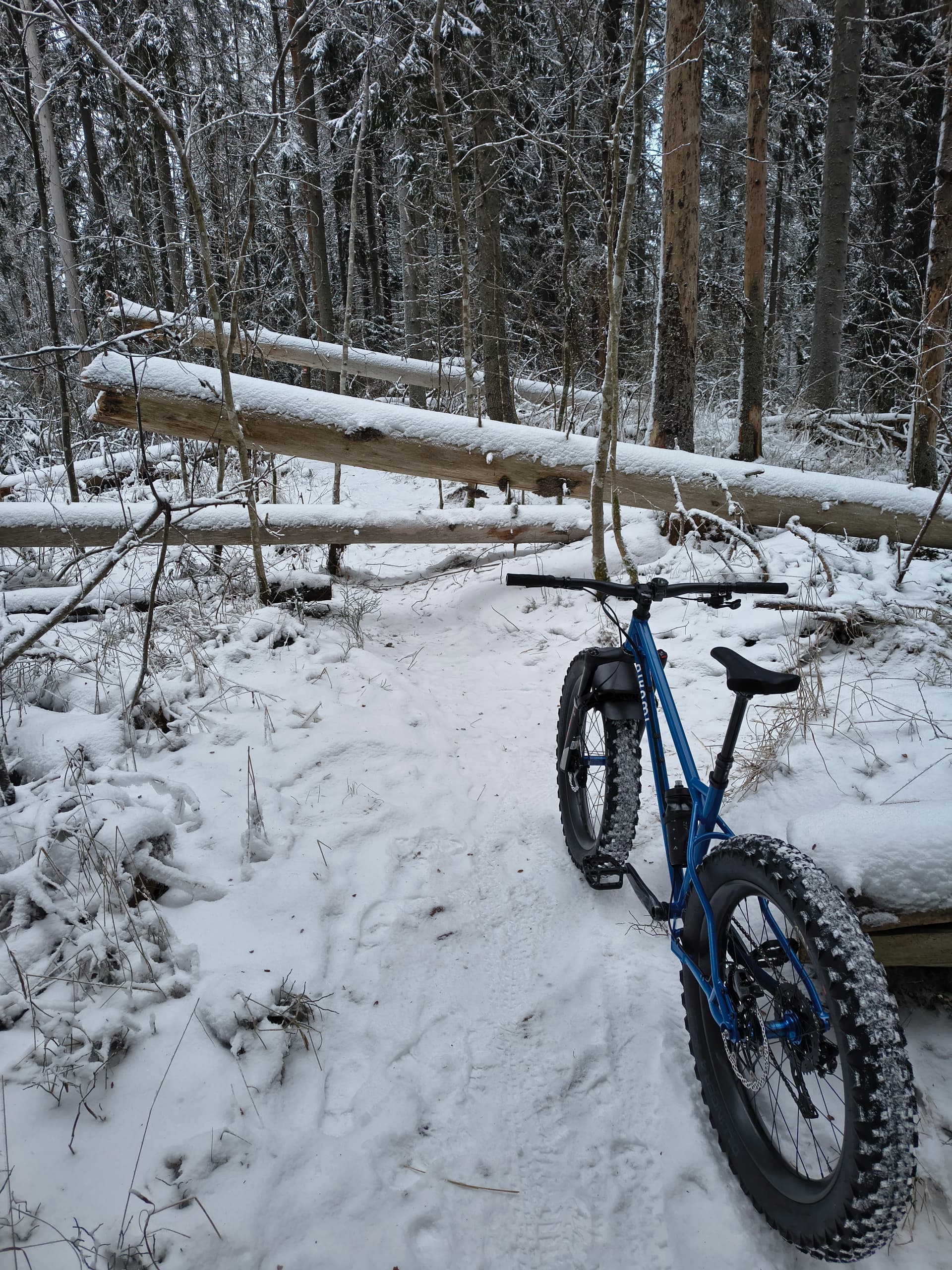
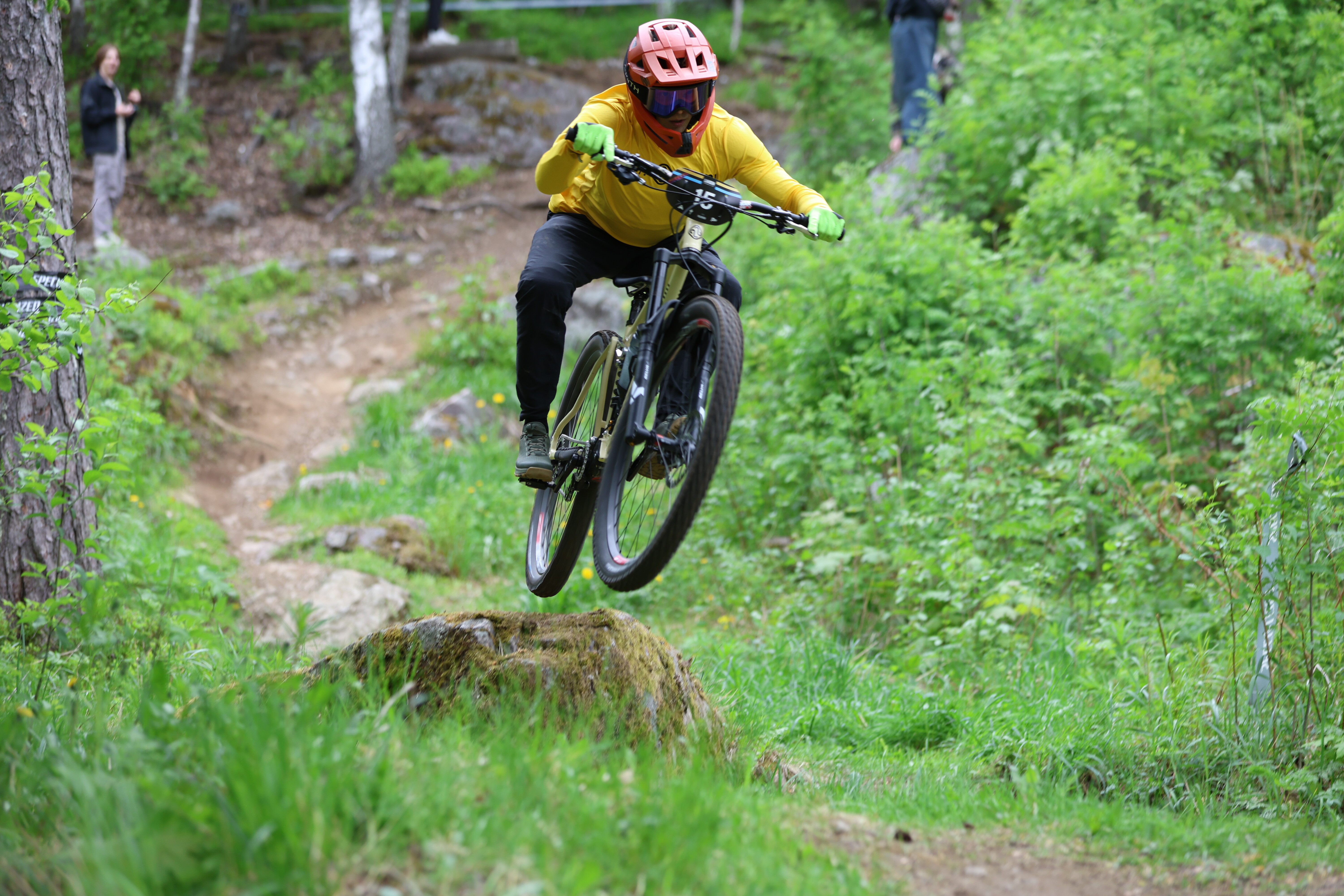
Went for a quick ride today with Pulska. It’s been quite windy and cold here lately :smiley:

I thought about the geo a lot while riding, and atleast on the undulating trails that we have here, it’s very close to perfect. I had two pedal strikes also so I don’t think the BB is too high :grinning_face_with_smiling_eyes: It is very easy to switch between this and the enduro bike when the geo is almost the same. With Farley there was always a long adjustment period.

But of course on long flat sections there is some extra weight on the hands, compared to a traditional geo, and that is the only tradeoff I can think.

Otherwise, the frame came out maybe a bit too stiff on the front, could have probably done without the HT gusset tube. I also have a super stiff carbon bar (for keeping hands a bit warmer) on this which adds on top of that.

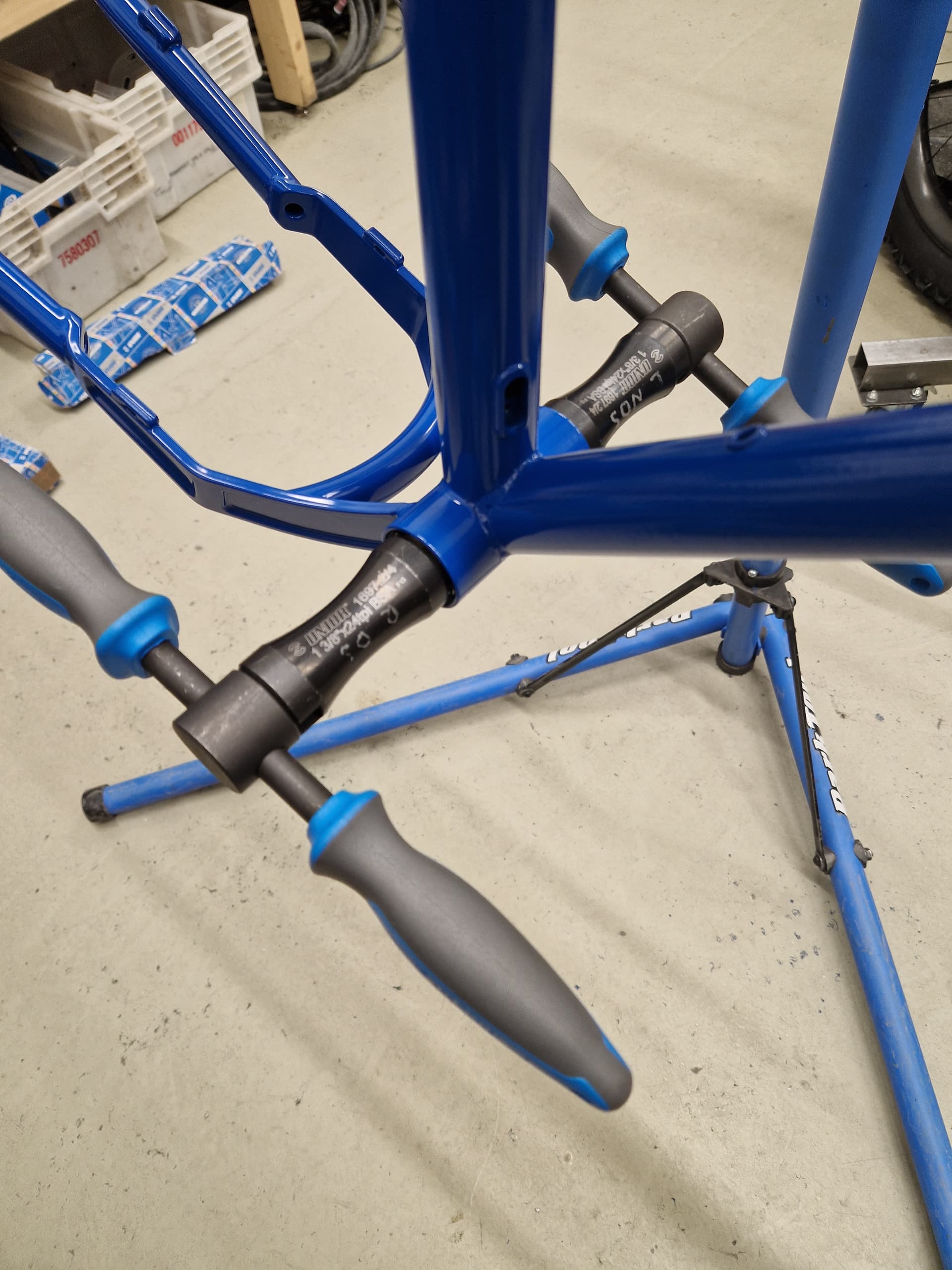
The Pulska has a 82mm BB, with SB+ cranks, which are only few mm wider than T-Type cranks. Which I really like since I’m not that tall / wide person :grimacing:

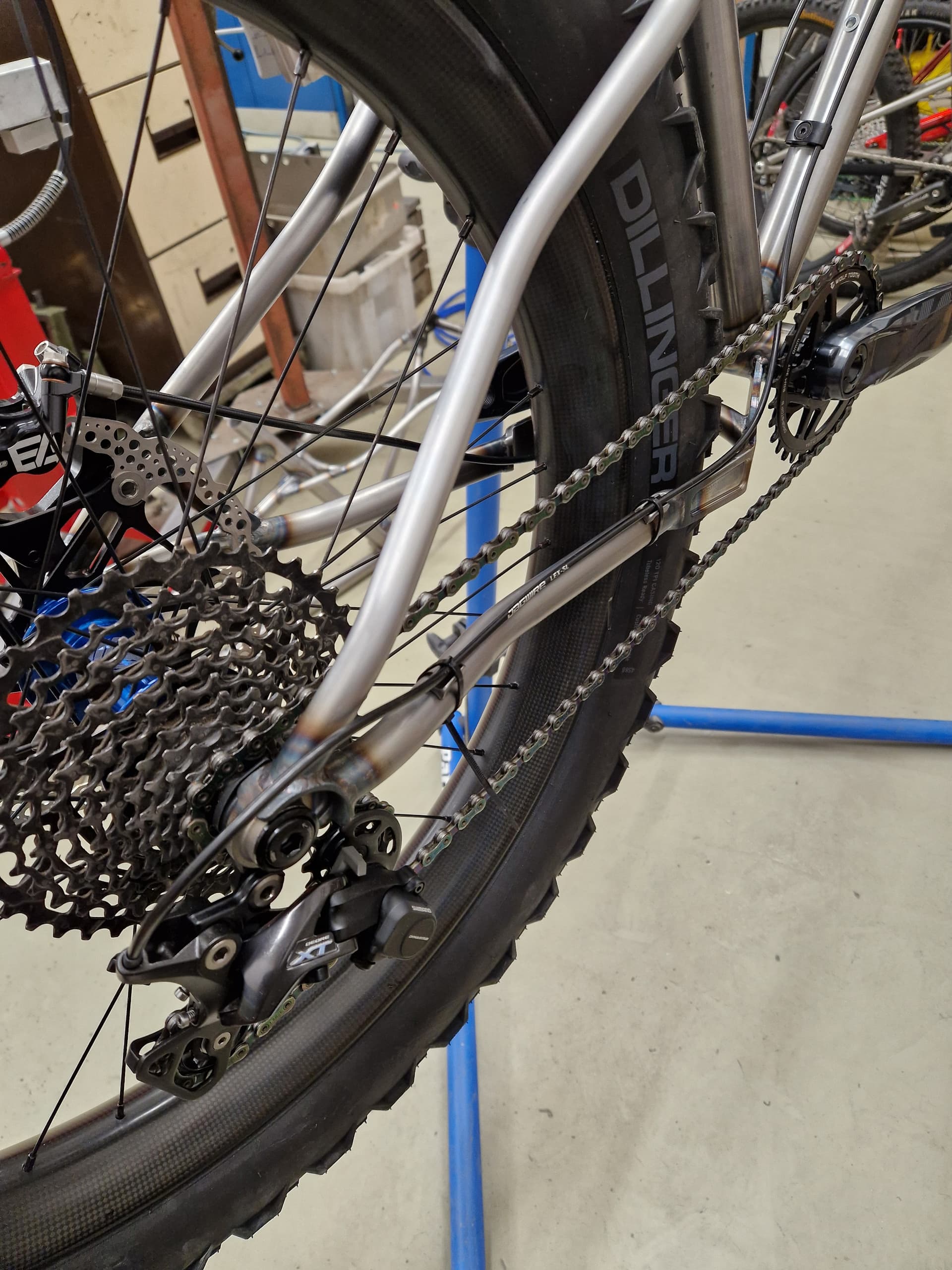
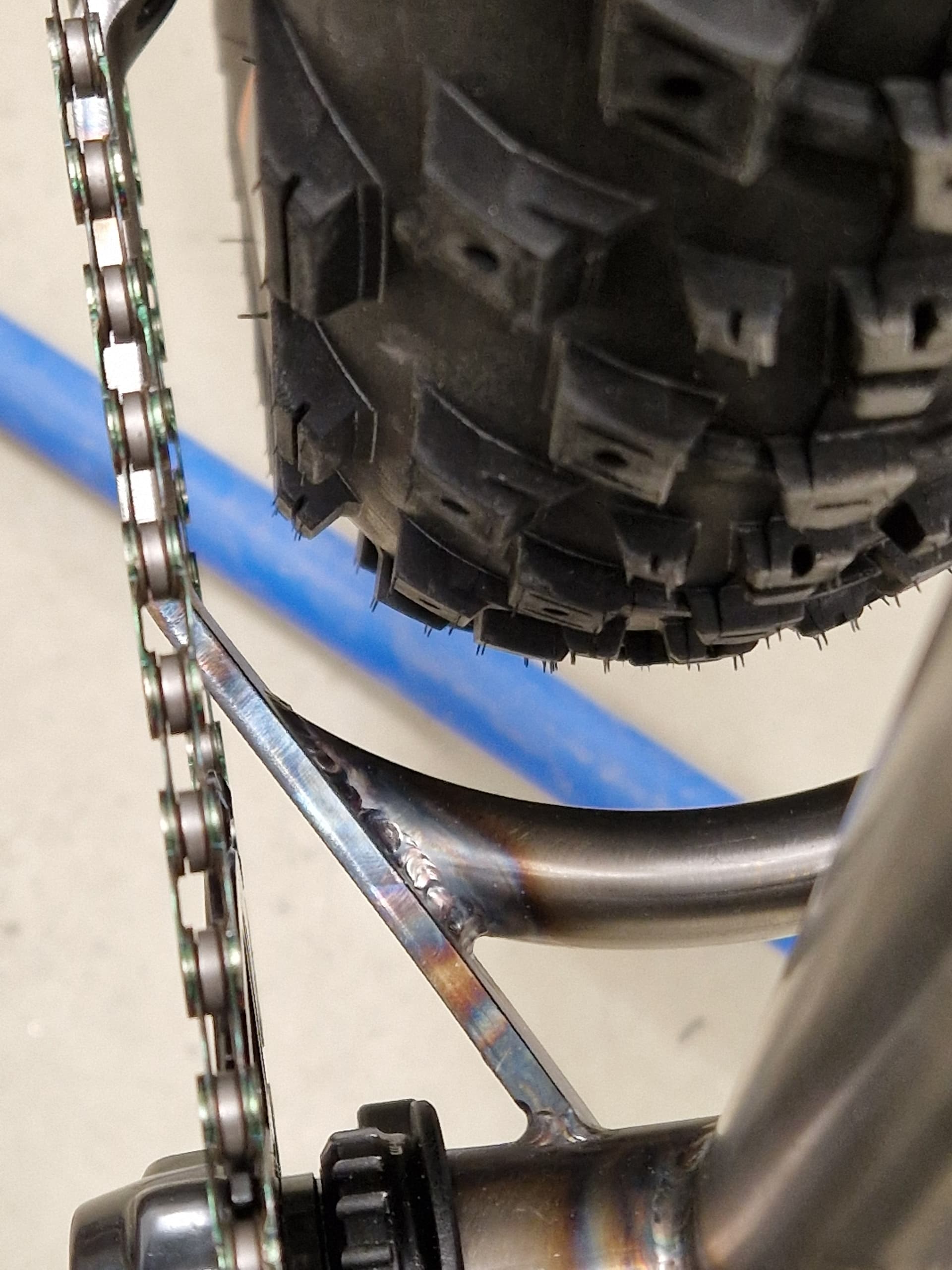
I made it work with a 0-offset Wolftooth chainring and 177mm rear hub with 4,2” tires. Although there are some minor marks from the chain on the tire. But I haven’t noticed anything while riding so I don’t mind.

5 Likes

Okay, on to the v2!

The main goals for v2 were:

  • improve rear suspension lateral / torsional stiffness
  • improve manufacturability, especially on rear triangle
  • maintain mostly same geo
  • maintain mostly same kinematics (can be more progressive)

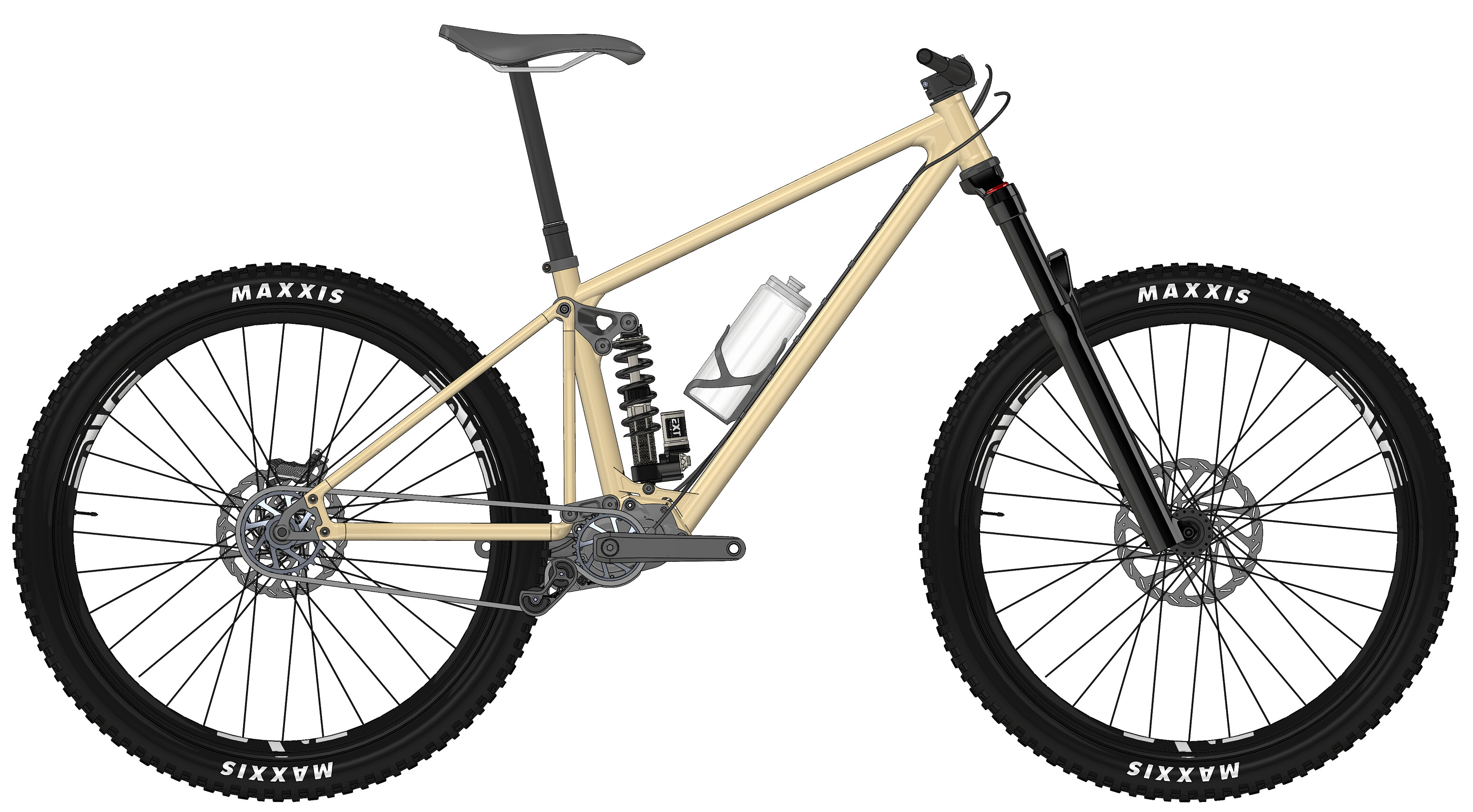
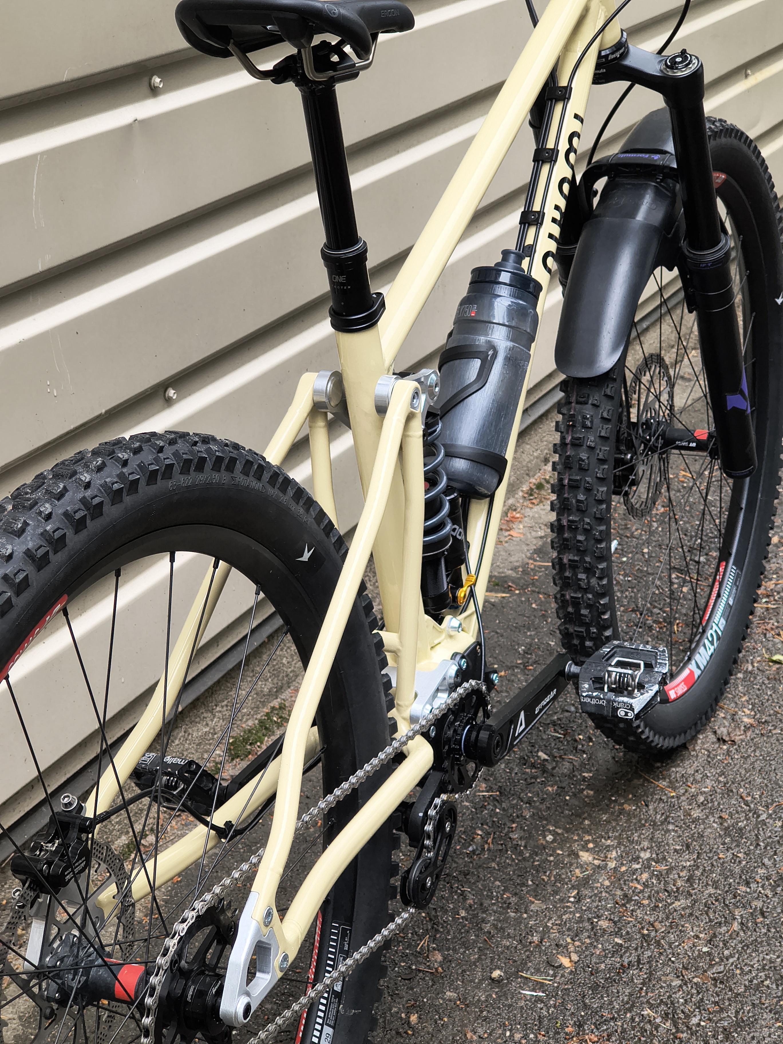
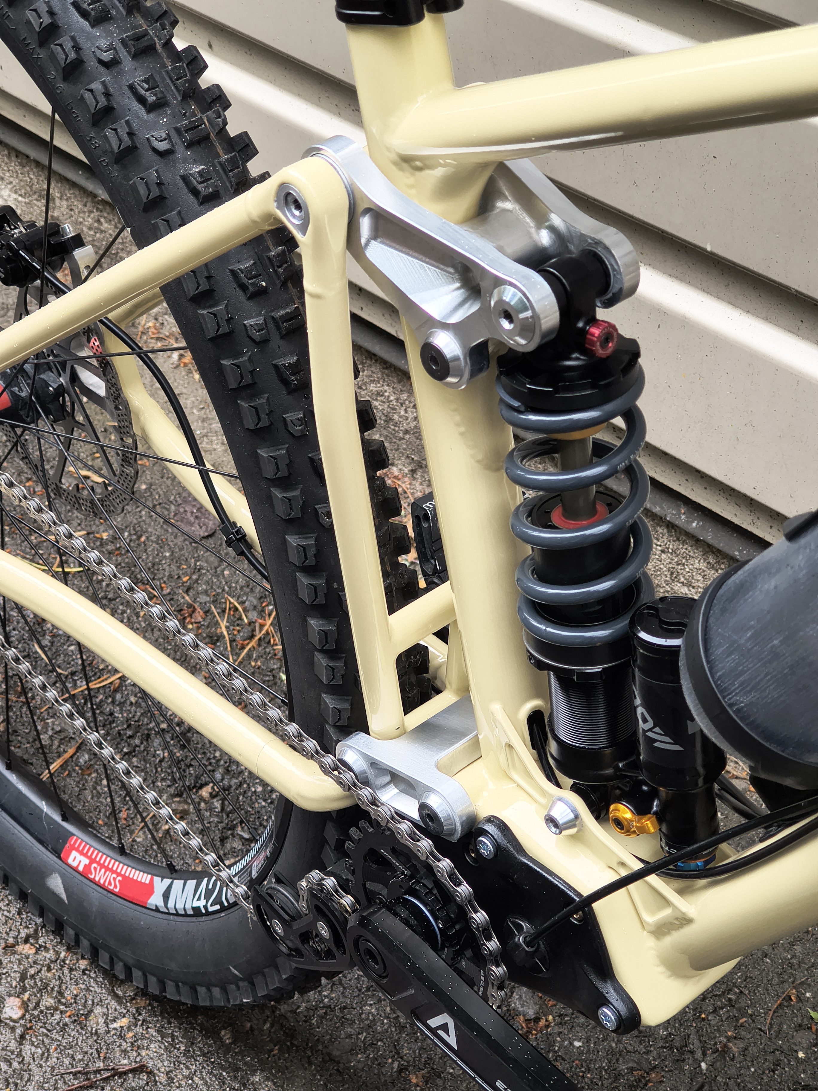
With these in mind, the main pitfall in v1 was the main pivot construction. Having main pivot bearings in frame with gearbox and a 24T chainring is next to impossible (without high-pivot), so I was intrigued by the dual-link (yes some Dave something, who knows, patent expired) design. In this design, the lower link has the much needed torsional stiffness while having the bearings outboard of the gearbox, so it can be packaged while having reasonable kinematics.

Big plus also on this design is that all the bearings can be in the machined aluminium parts, so the bores are not subjected to welding distortion.

A lot of the time that I spent was changing the pivot points 1mm here and there, rotating the gearbox 1 degree and going through all the variations again. Short dual link suspension is easily quite progressive and really sensitive on the pivot locations!!! At least when you don’t have much space.

Initial design while going back-and-forth in Linkage X3:

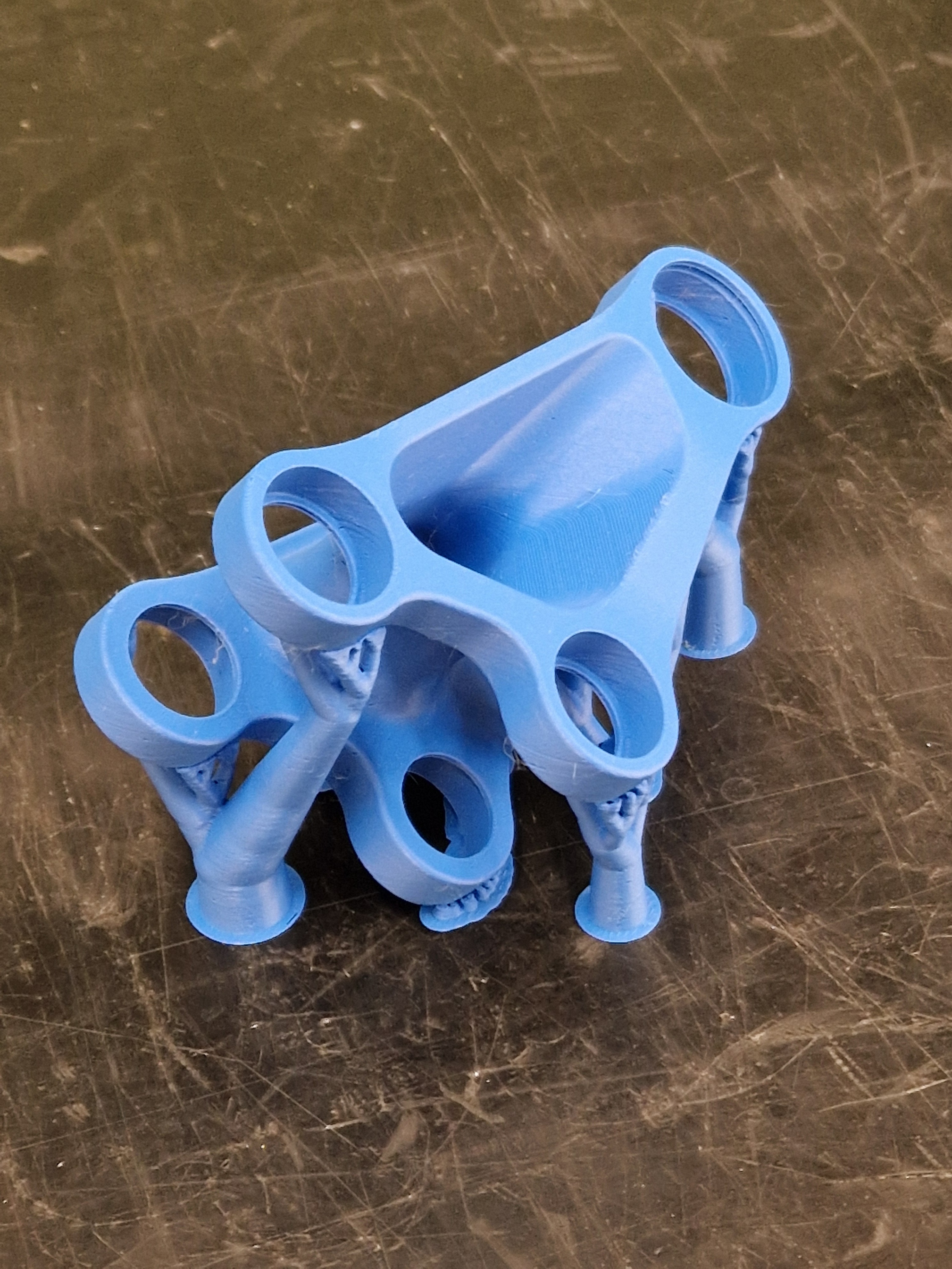
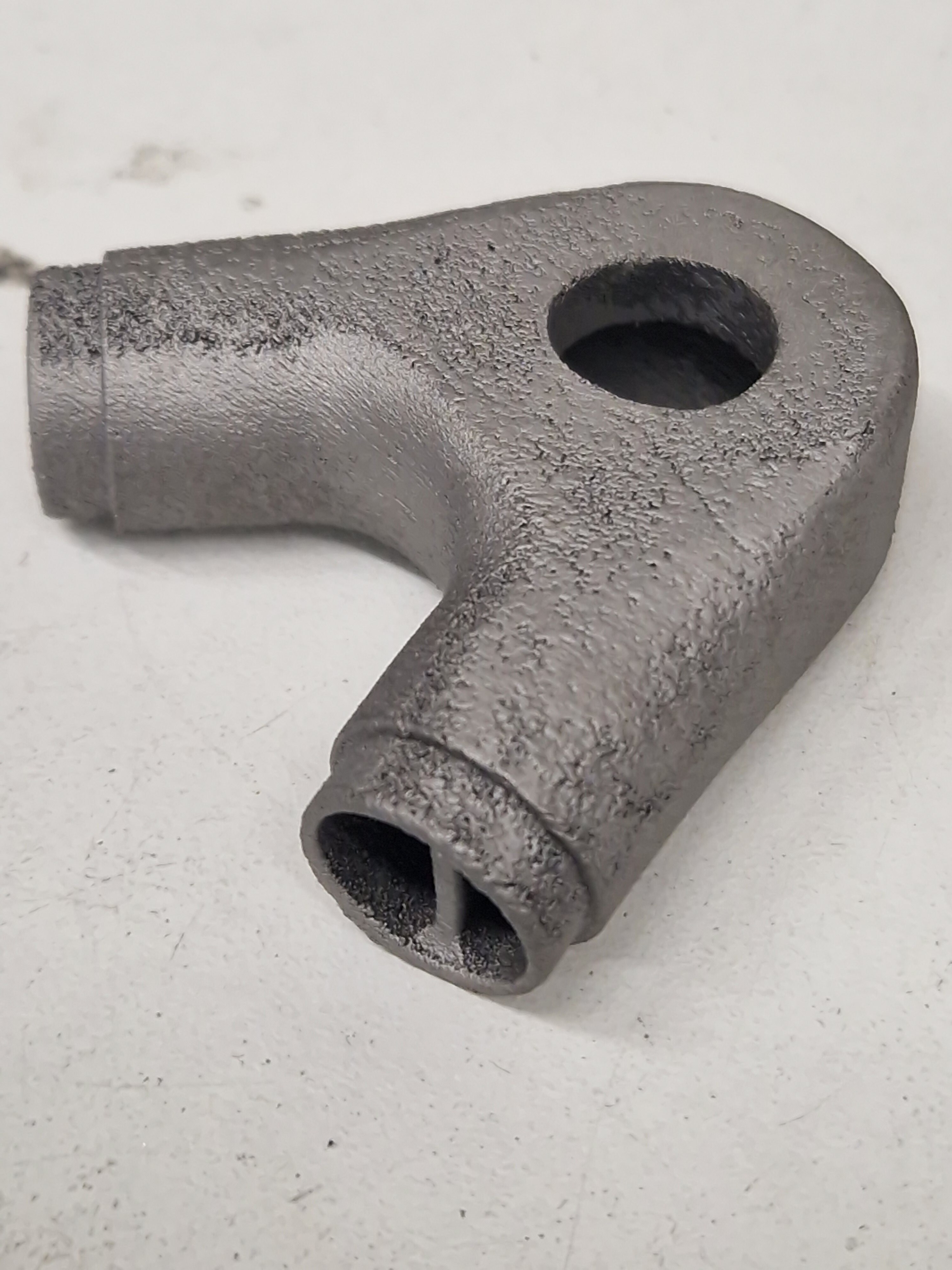
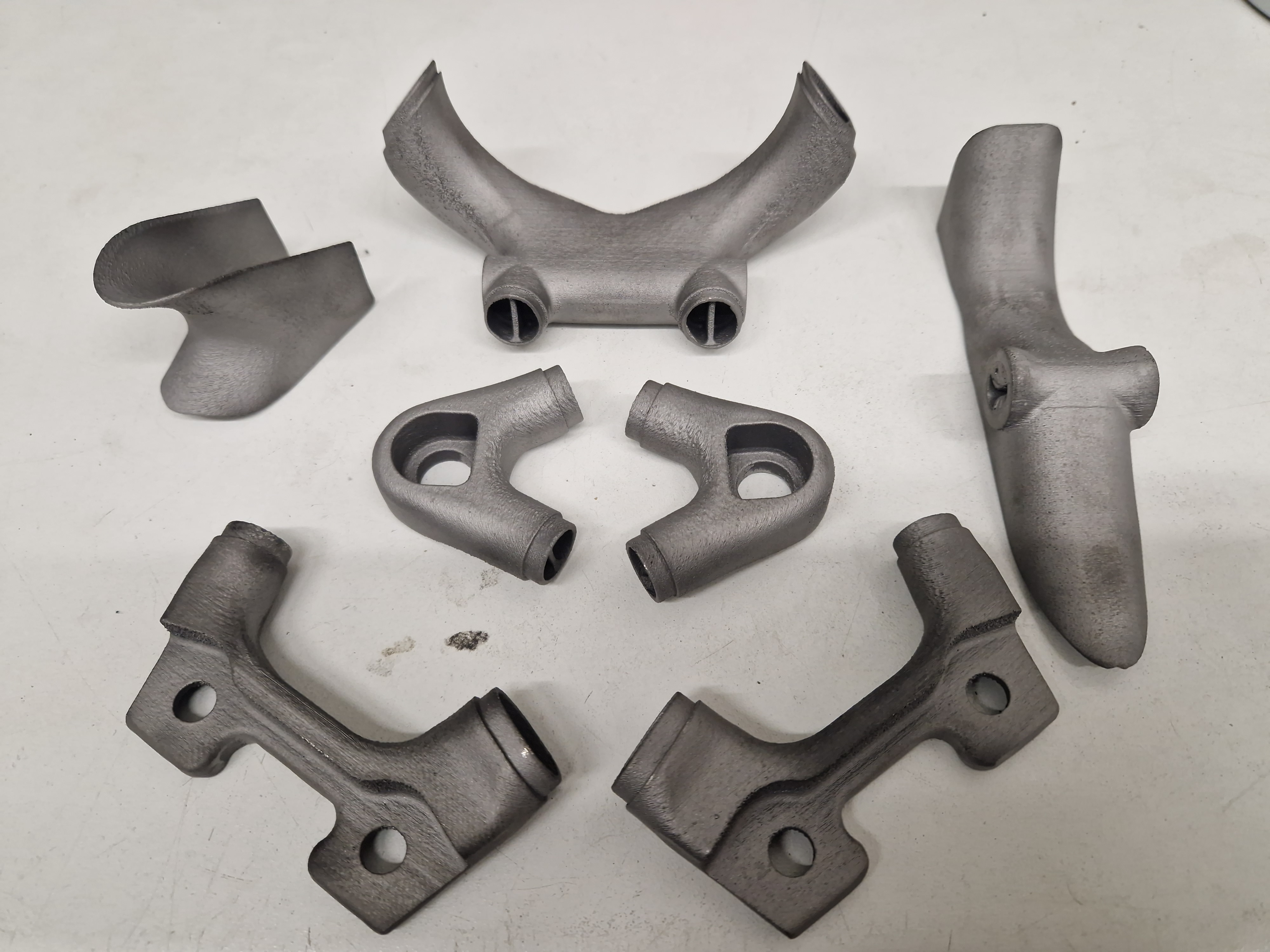
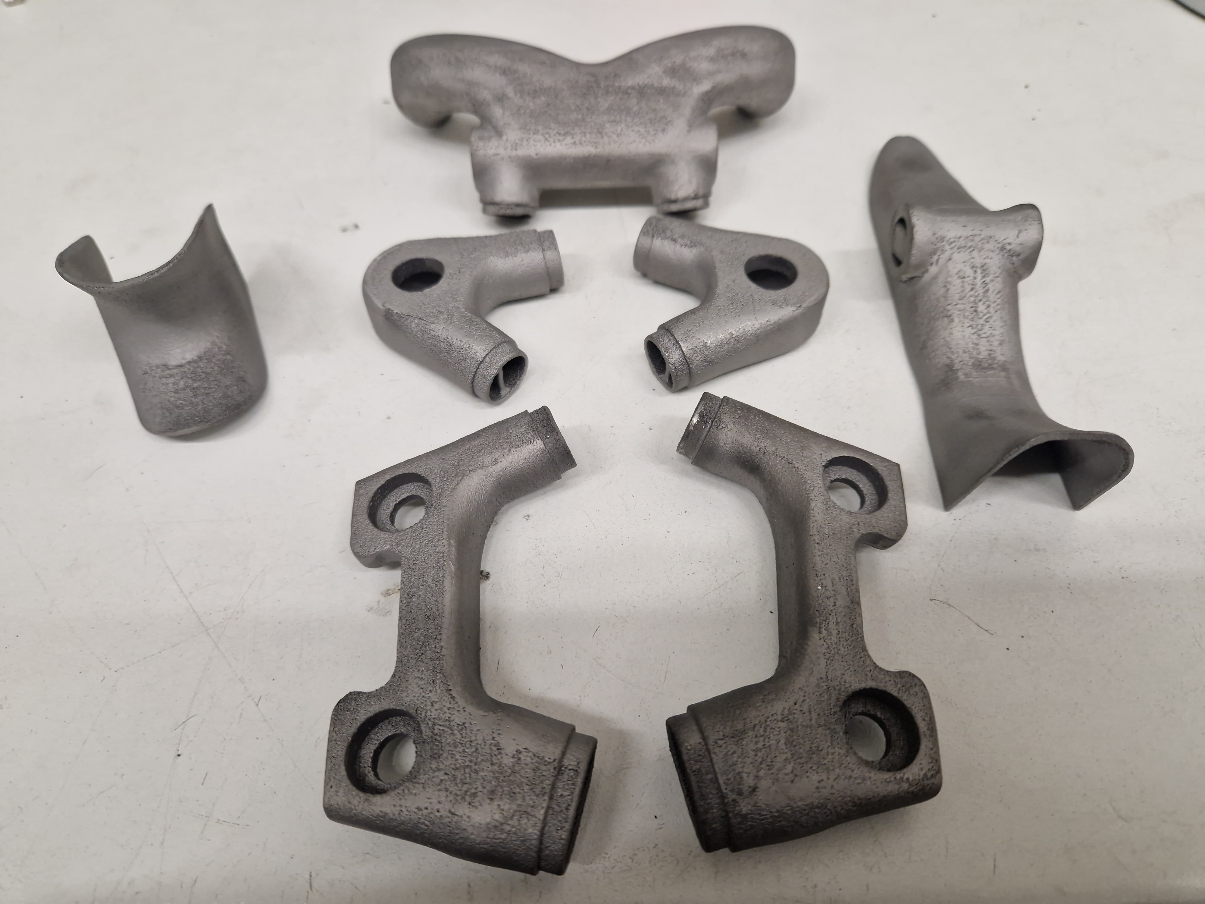
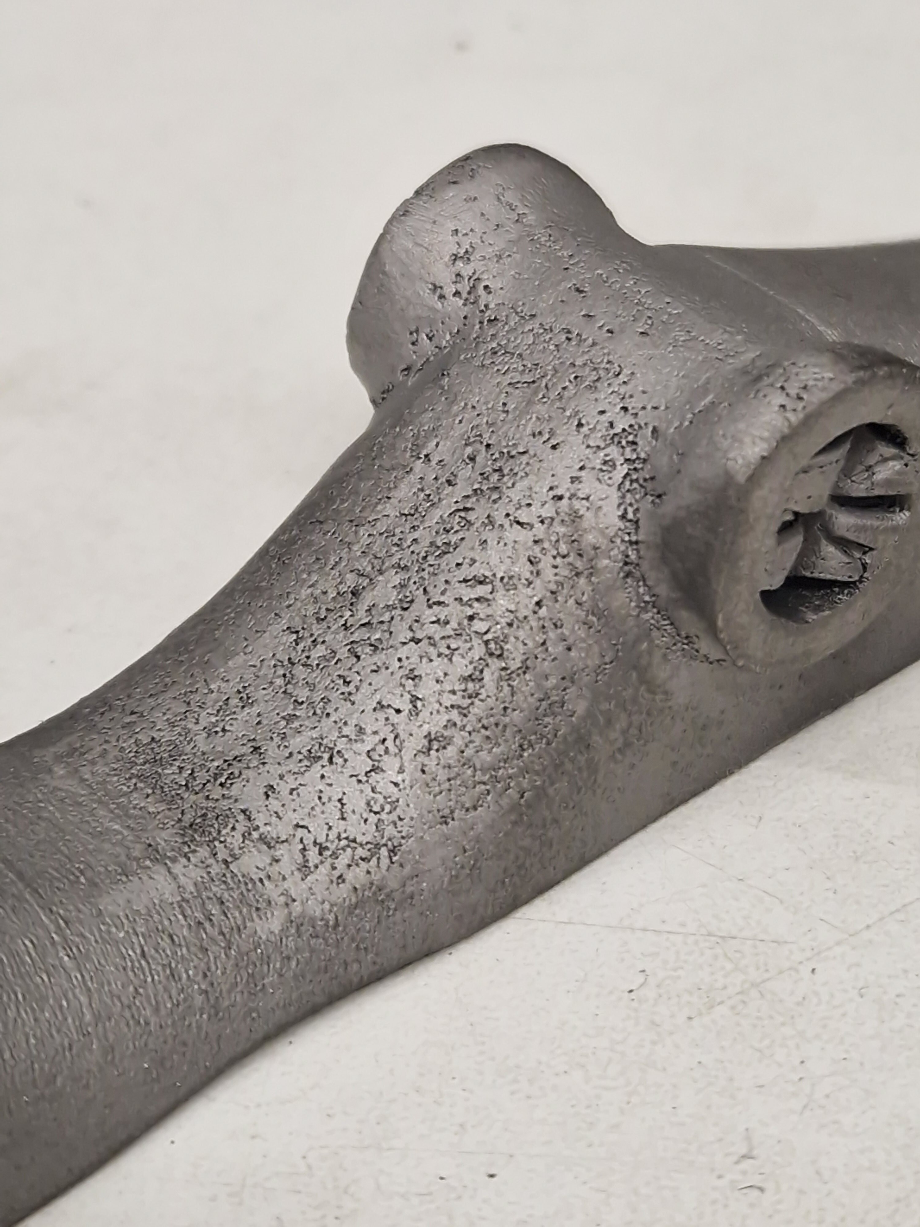
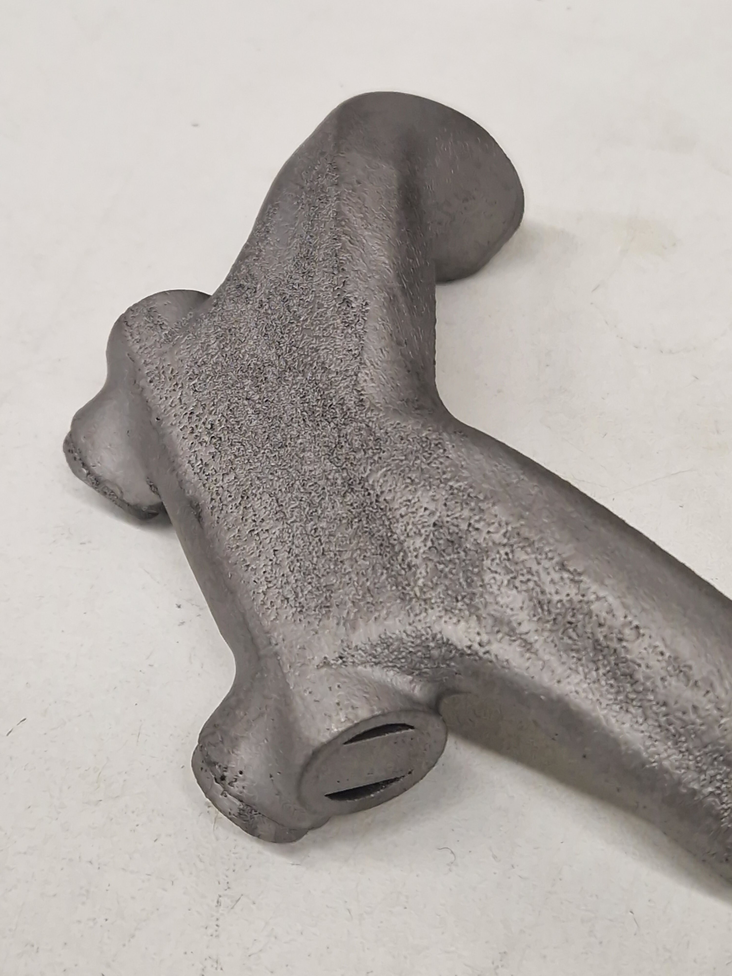
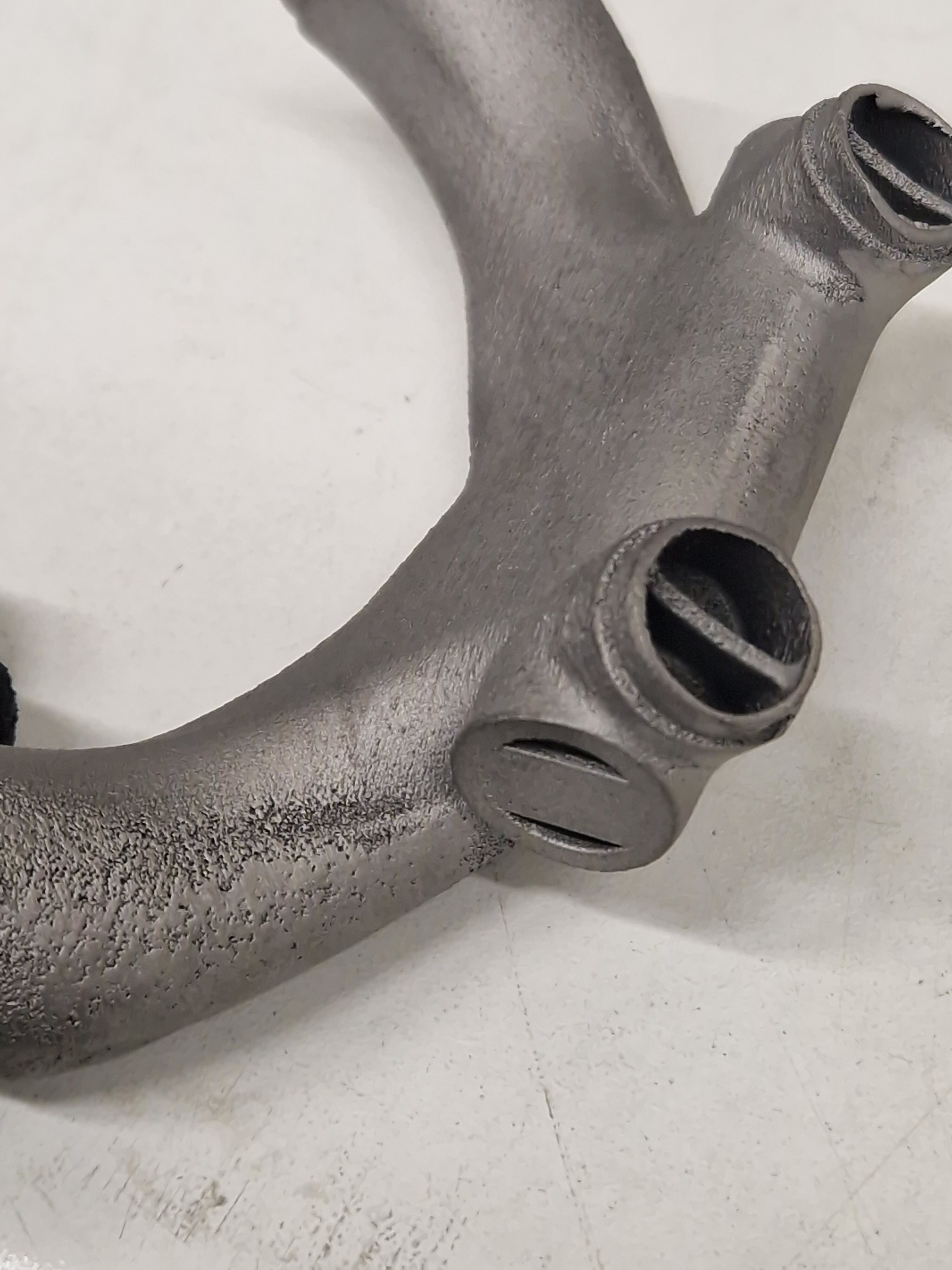
The rear suspension really screamed for 3D-printed parts, so early on, I started to model the parts as printed. You can tell I really struggled with SolidWorks Loft-feature :rofl: Total PITA. Should have learned Surface-modeling perhaps…

Clearance is clearance!

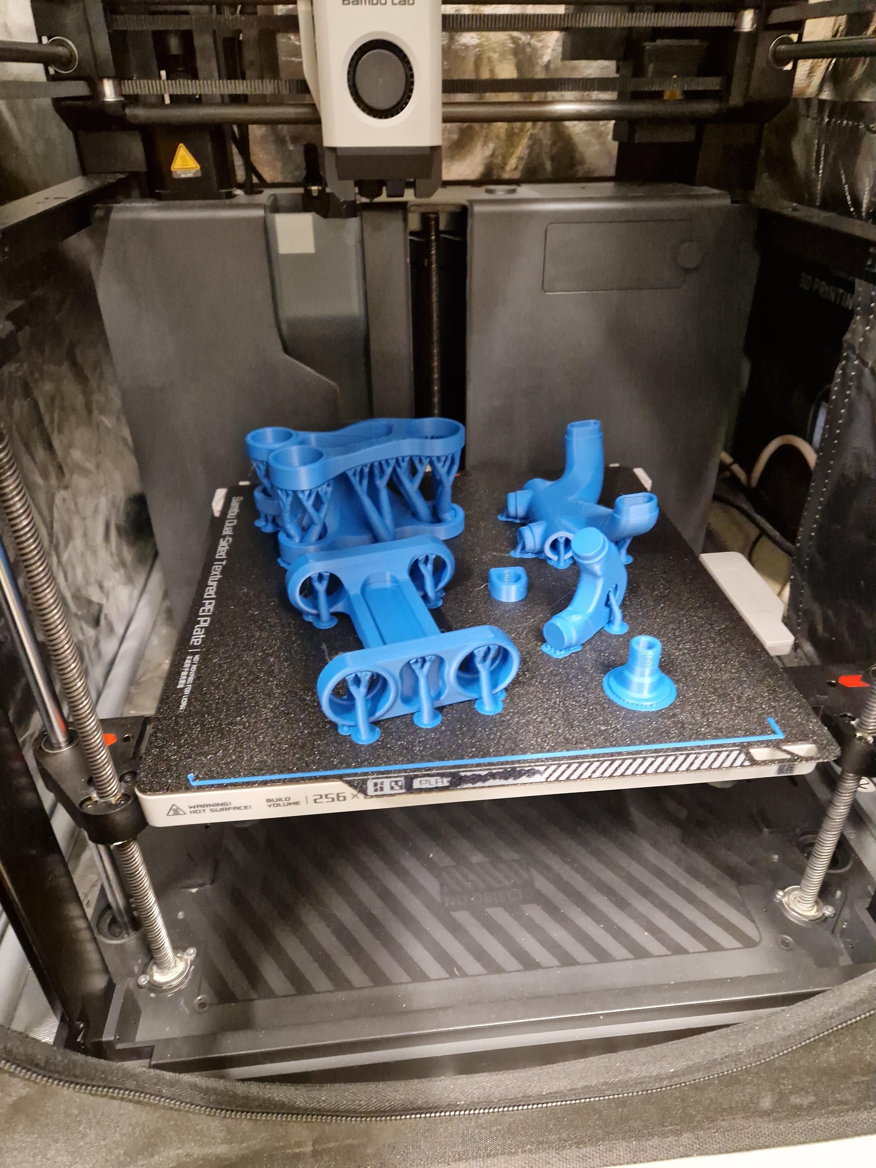
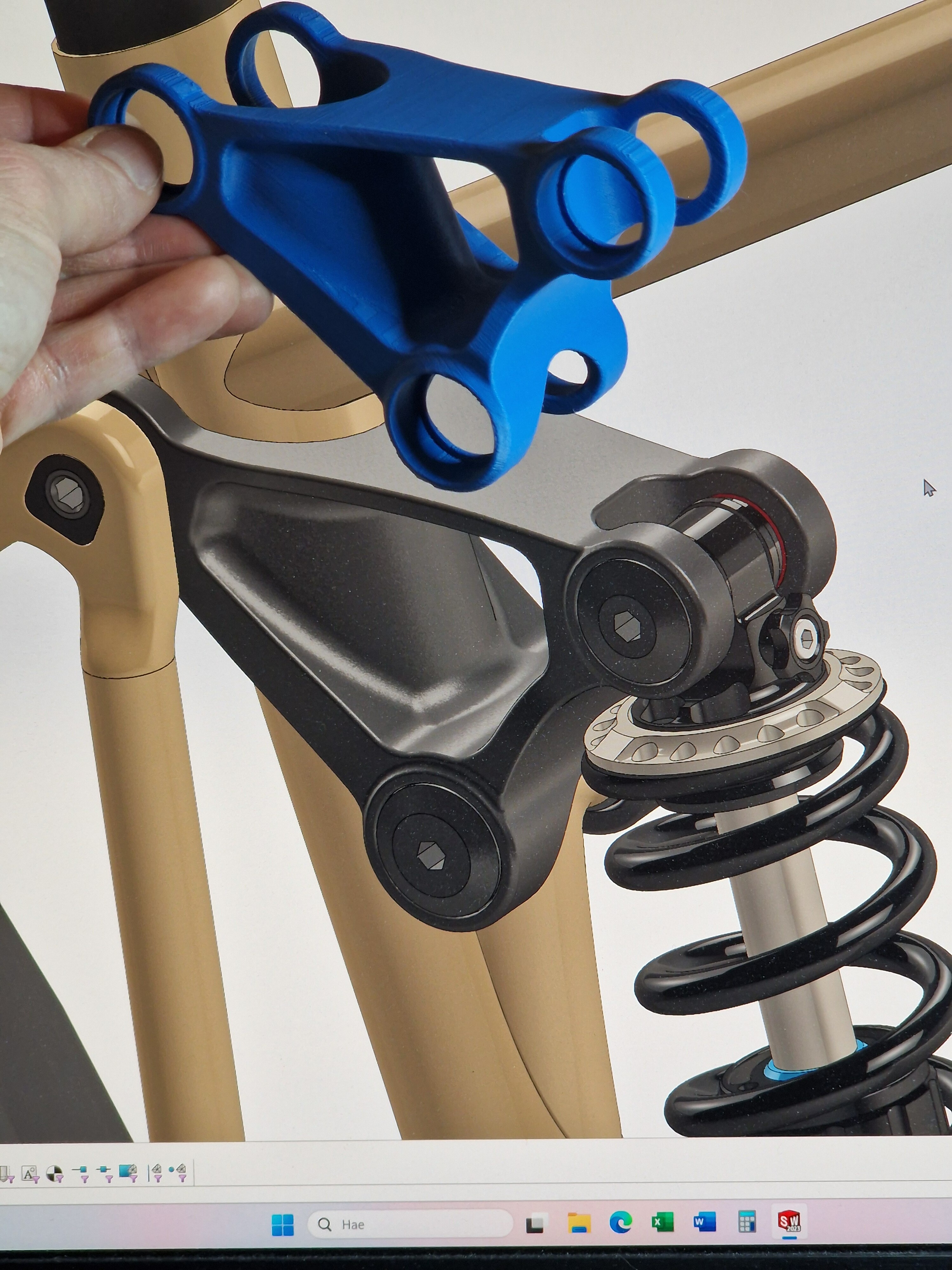
Say yes to PLA 3D-printing your designs before going too far! You get much better feeling of the structure.

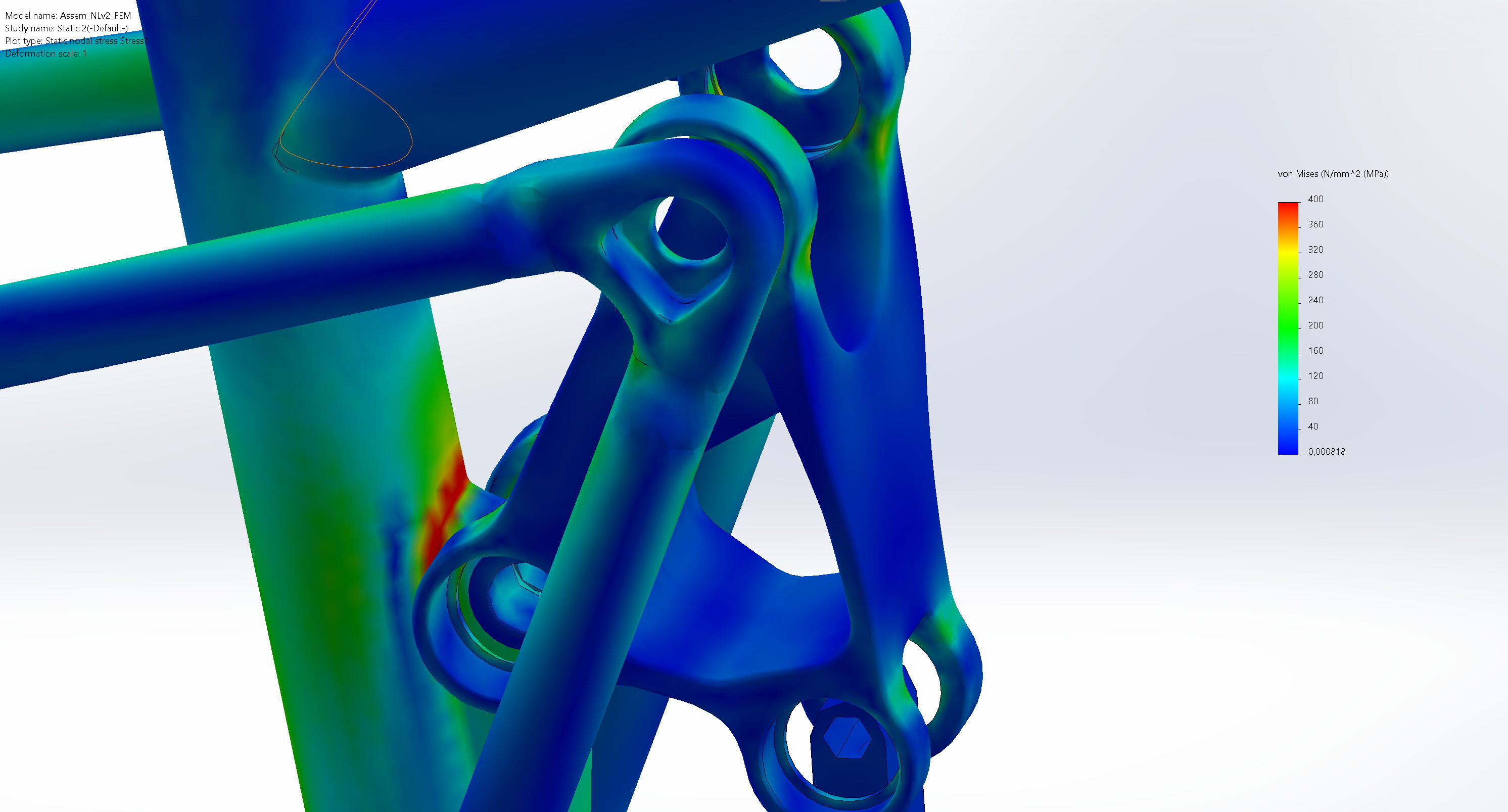
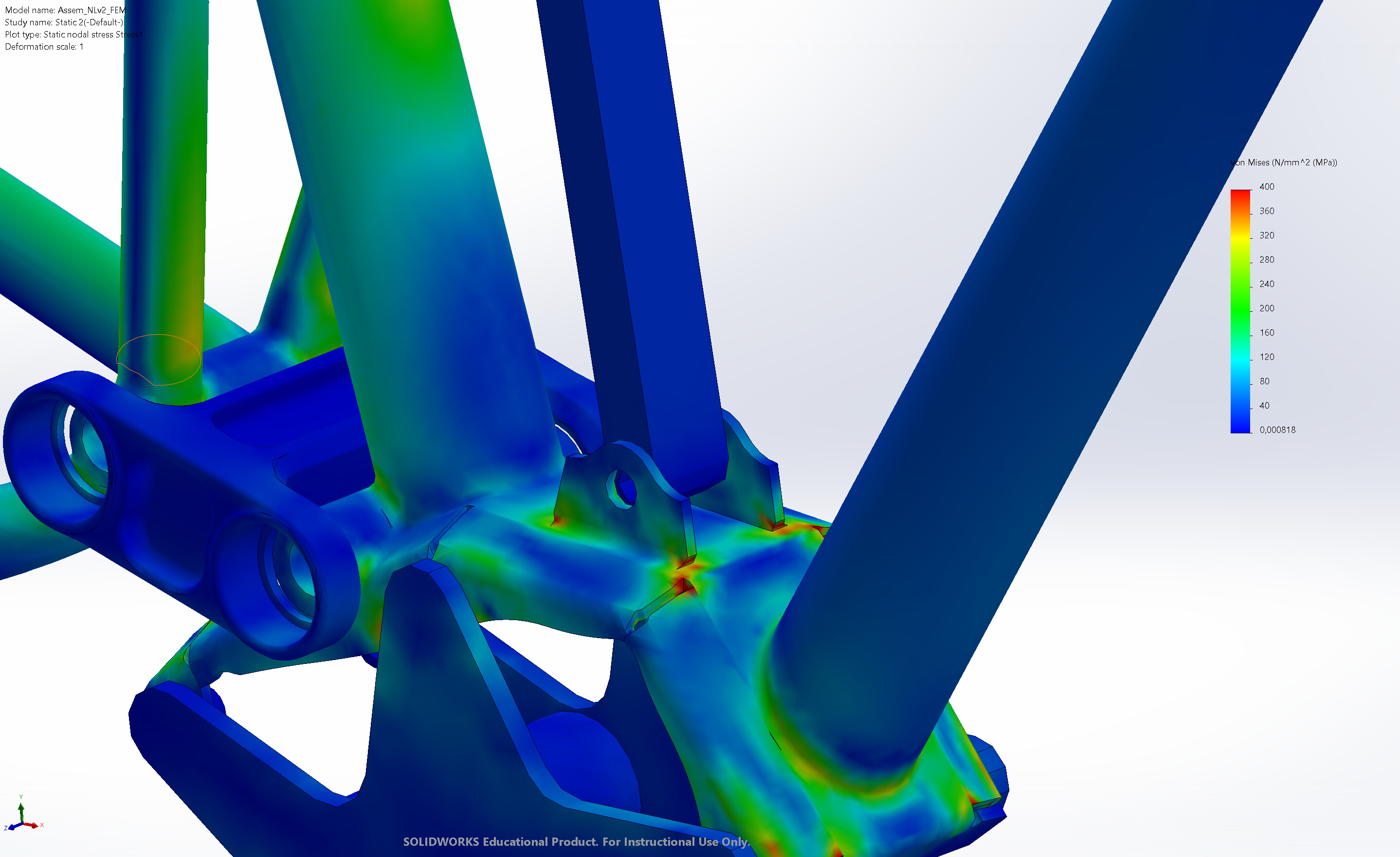
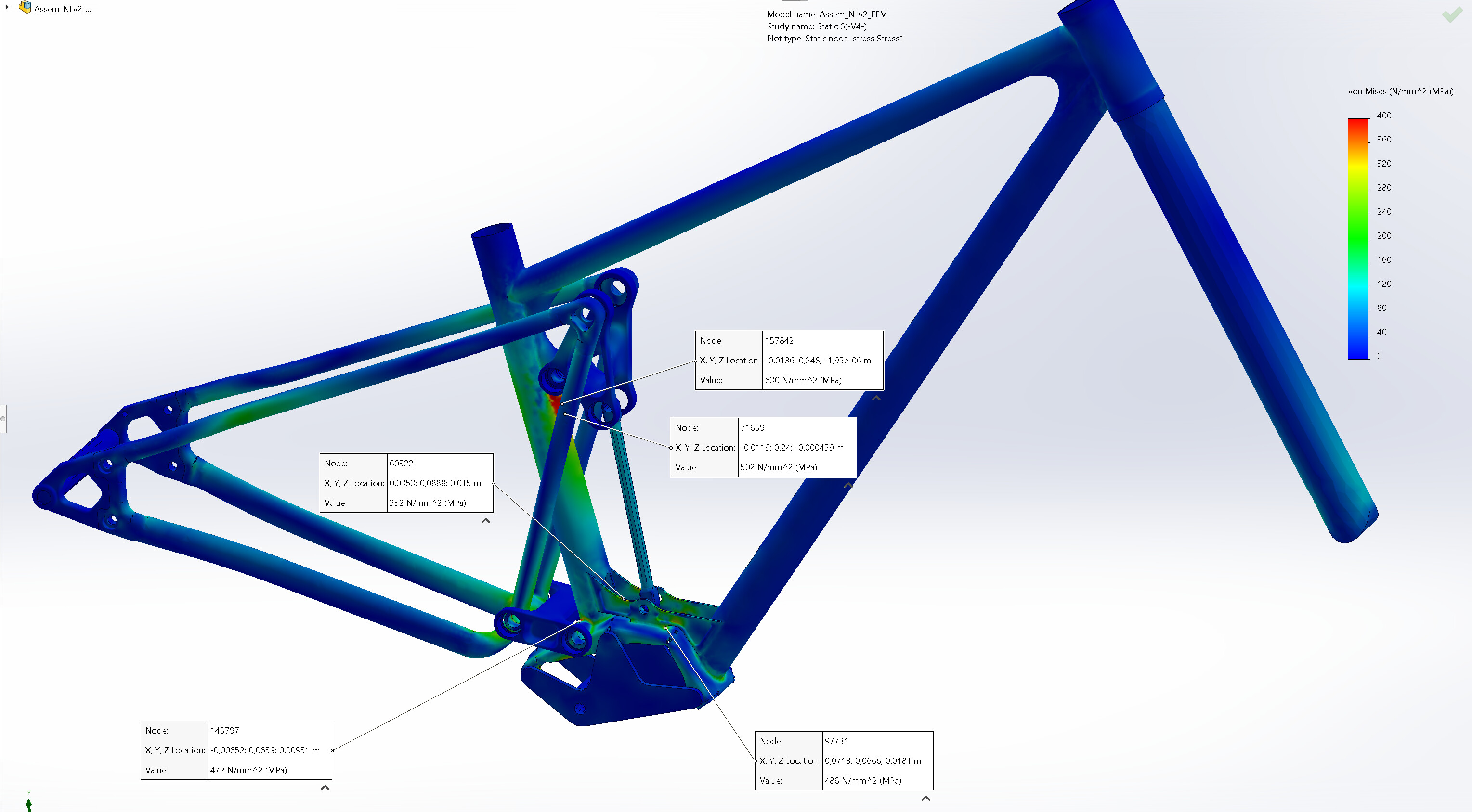
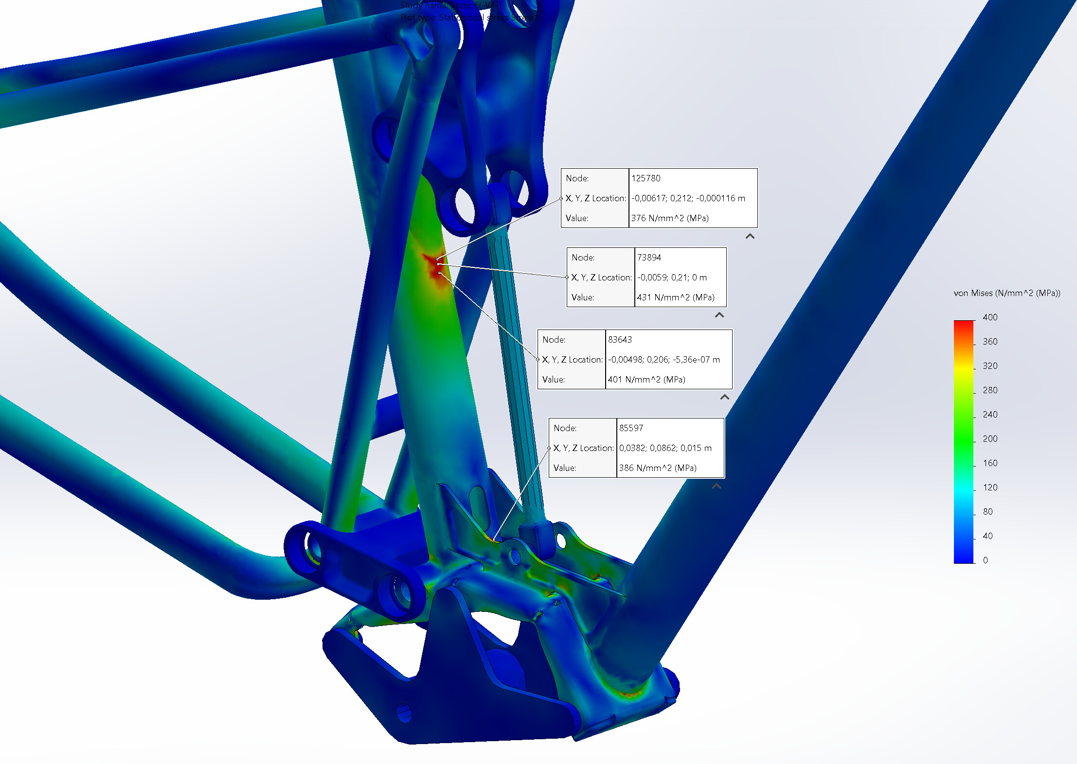
Some FEA to find the hotspots and drive the design forward.

Going through lots of options as always.

You can probably also tell I’m not an industrial designer :smiley: While doing a bike for myself with my own money, this is totally useless, but still! Kind of fun.

To be continued…
13 Likes

I’m not a very frequent poster, am I :smiley: There has been some getting used to the house, and fixing small things. I did paint the garage and got a lathe! Slowly towards a small shop within the house :star_struck:

10 Likes

Back to v2…
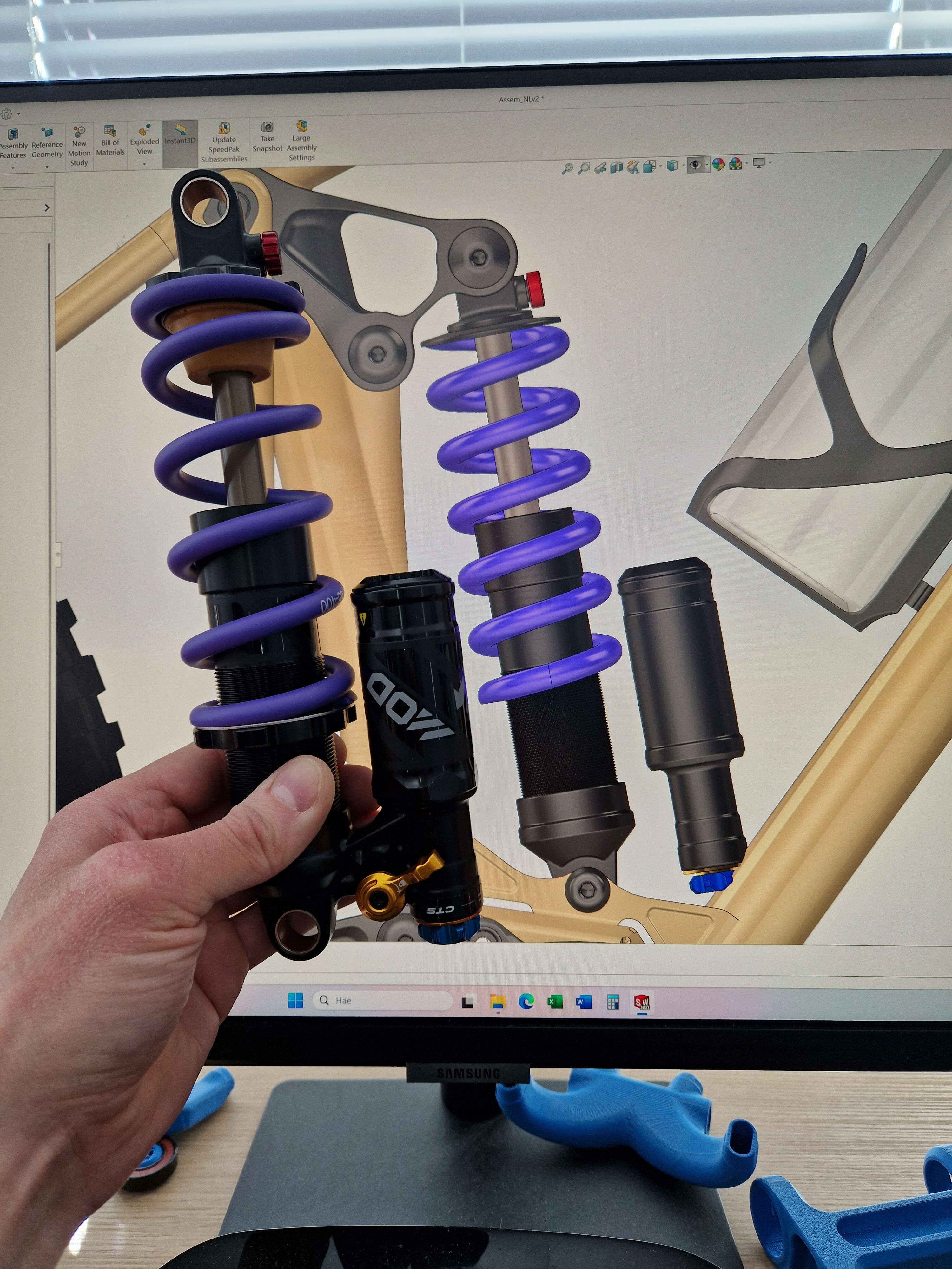
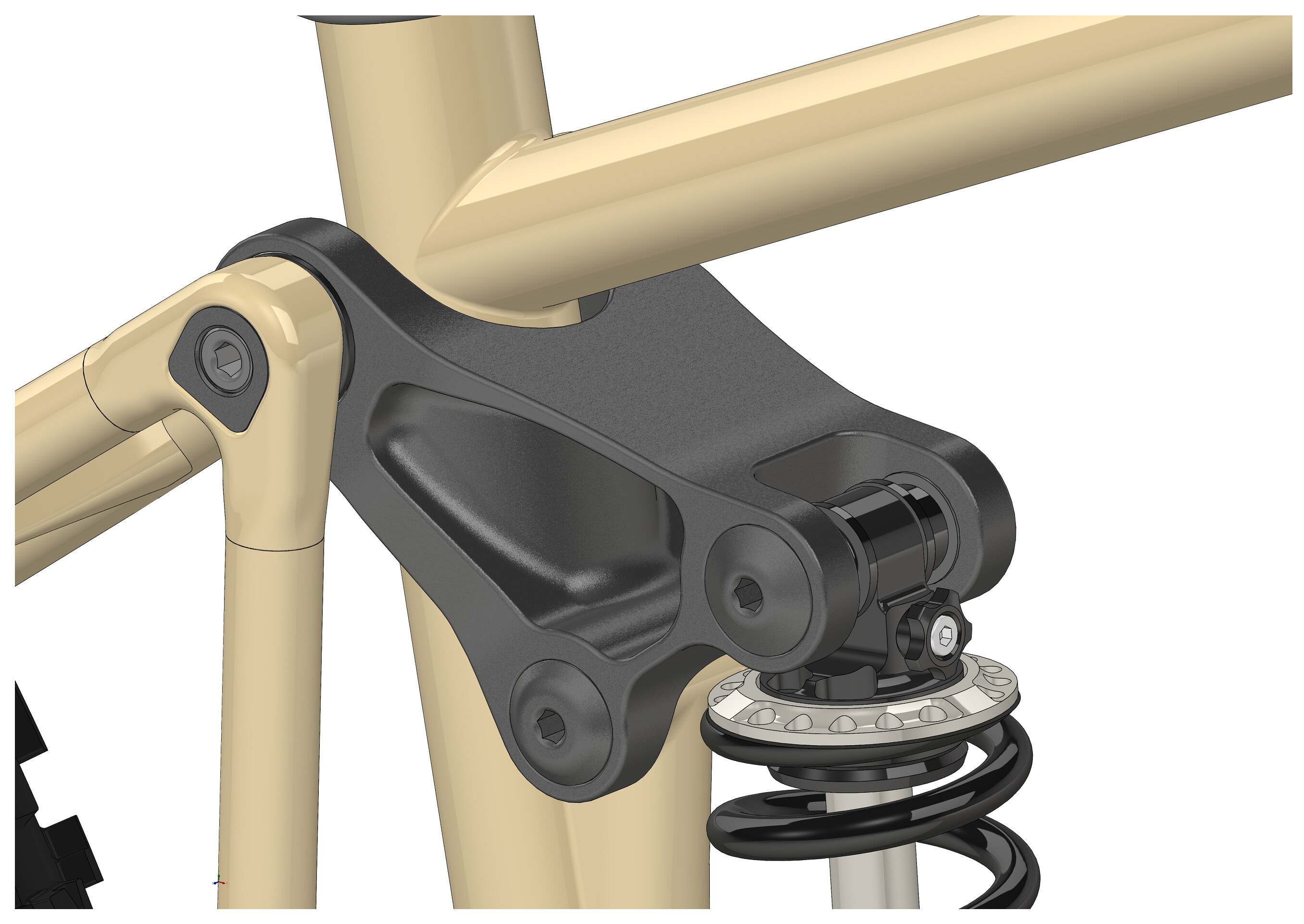
Checking clearances.

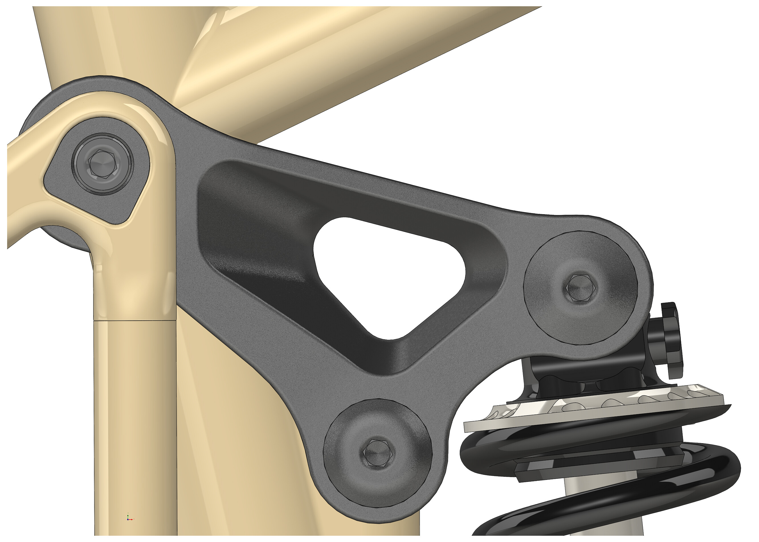
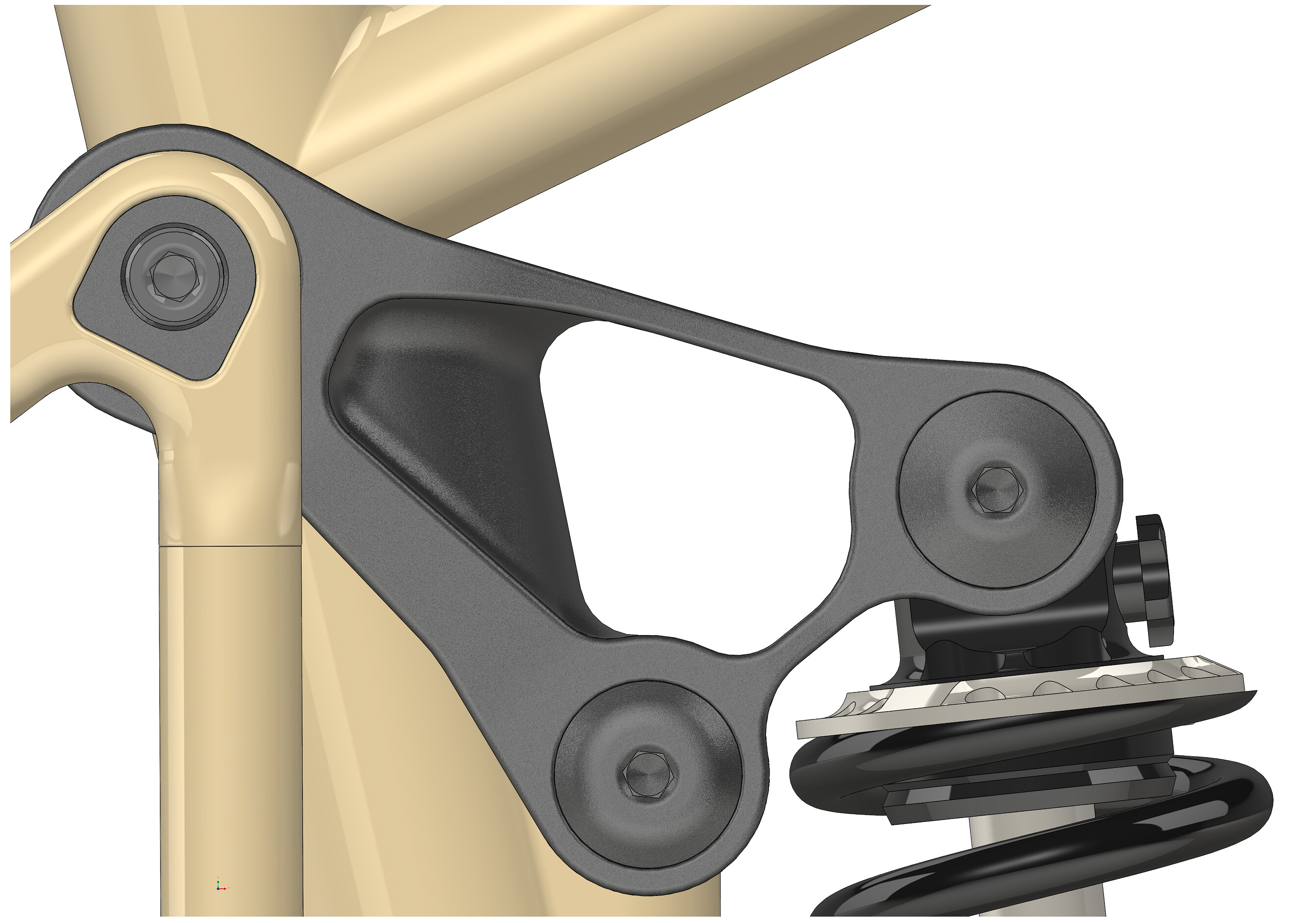
Few rocker designs.

About final.

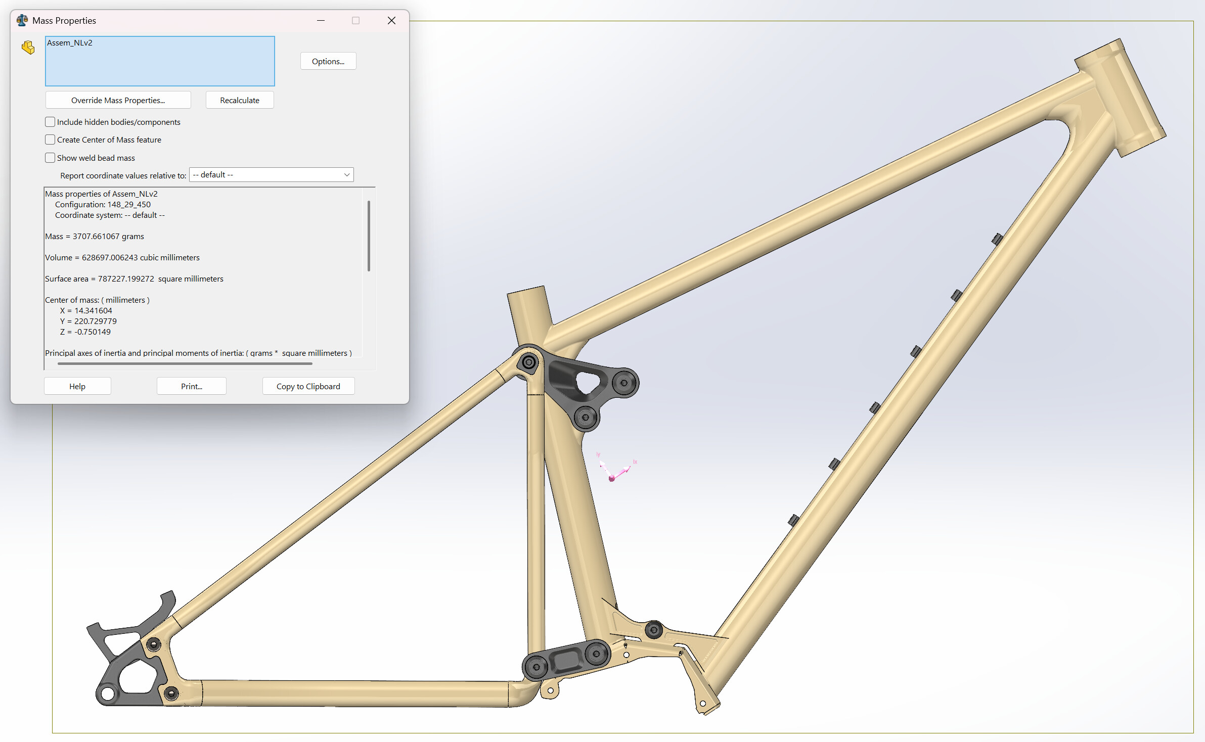
Weight still OK.

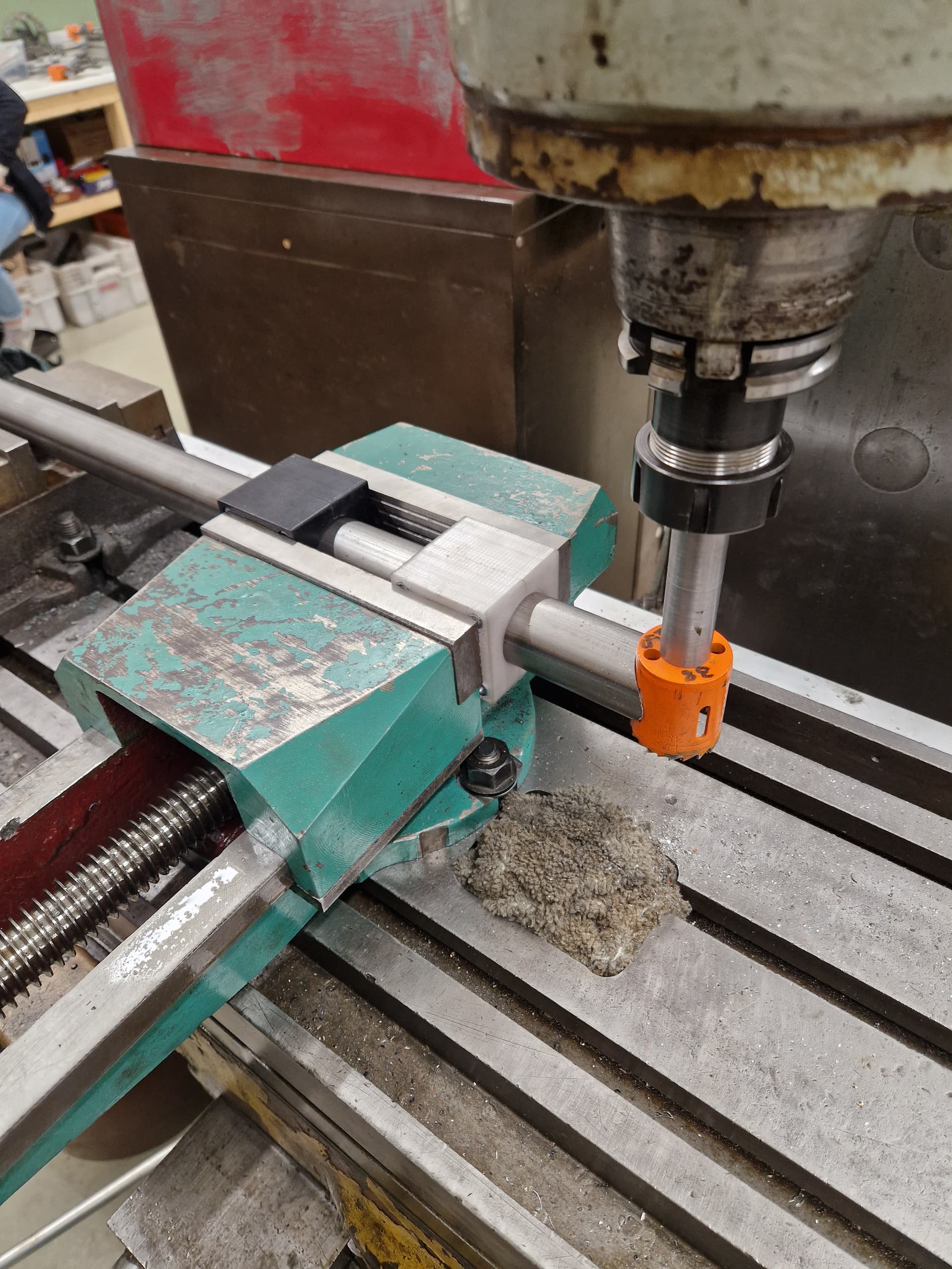
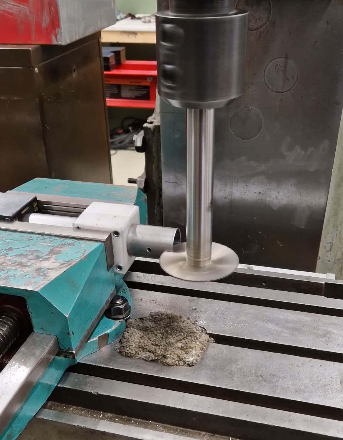
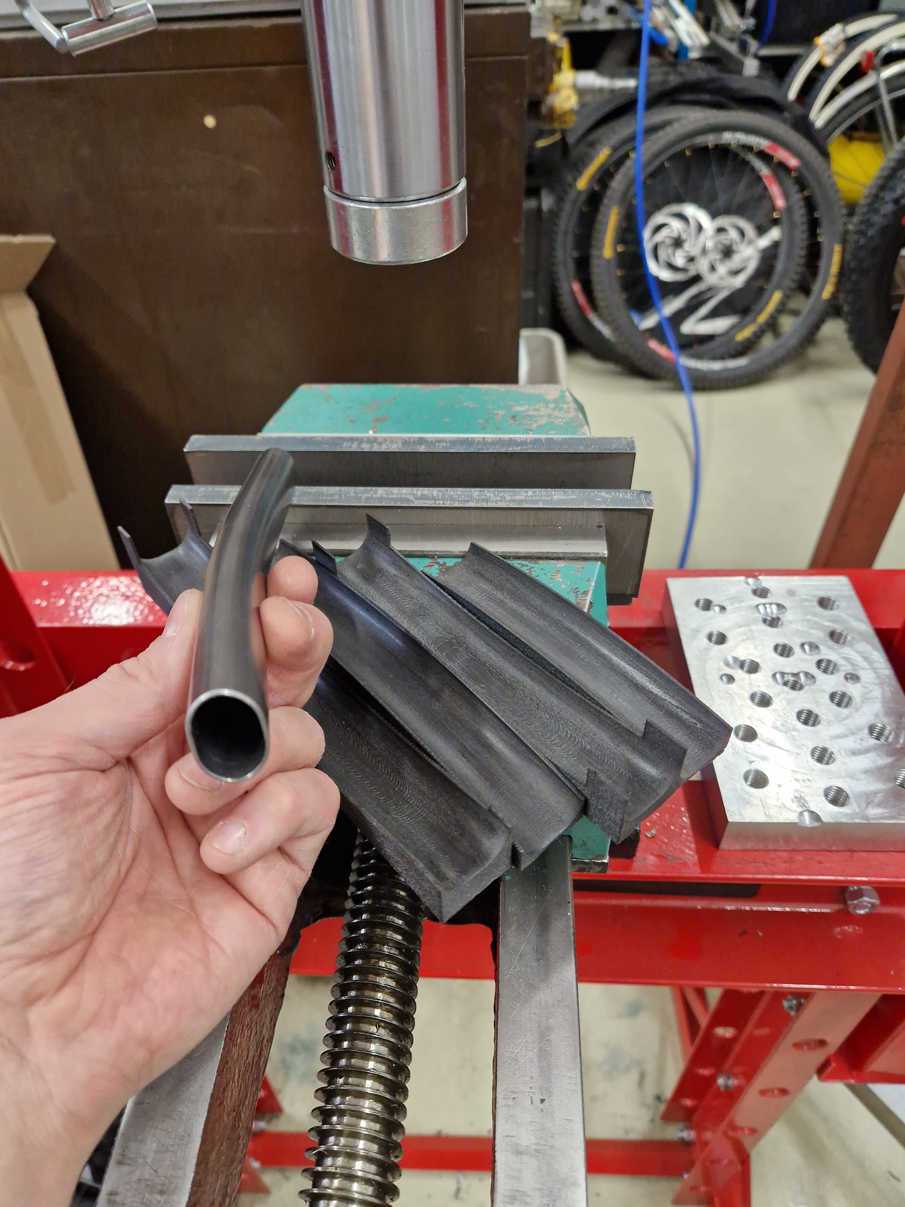
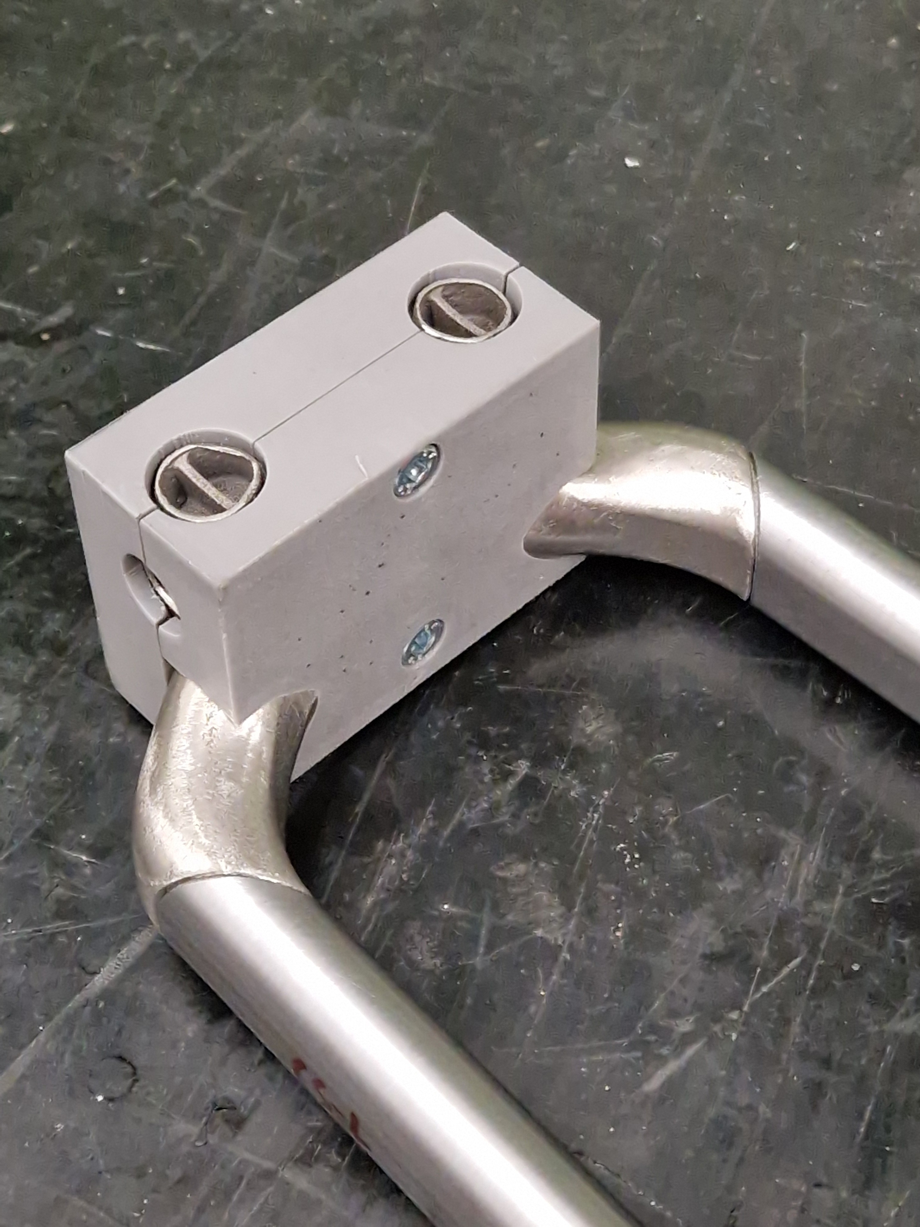
Test bends with 3D-printed die, for squished 20x1 mm Docol.

FEA seems endless. Some high stress points in seat tube / rocker mount.

Close enough.

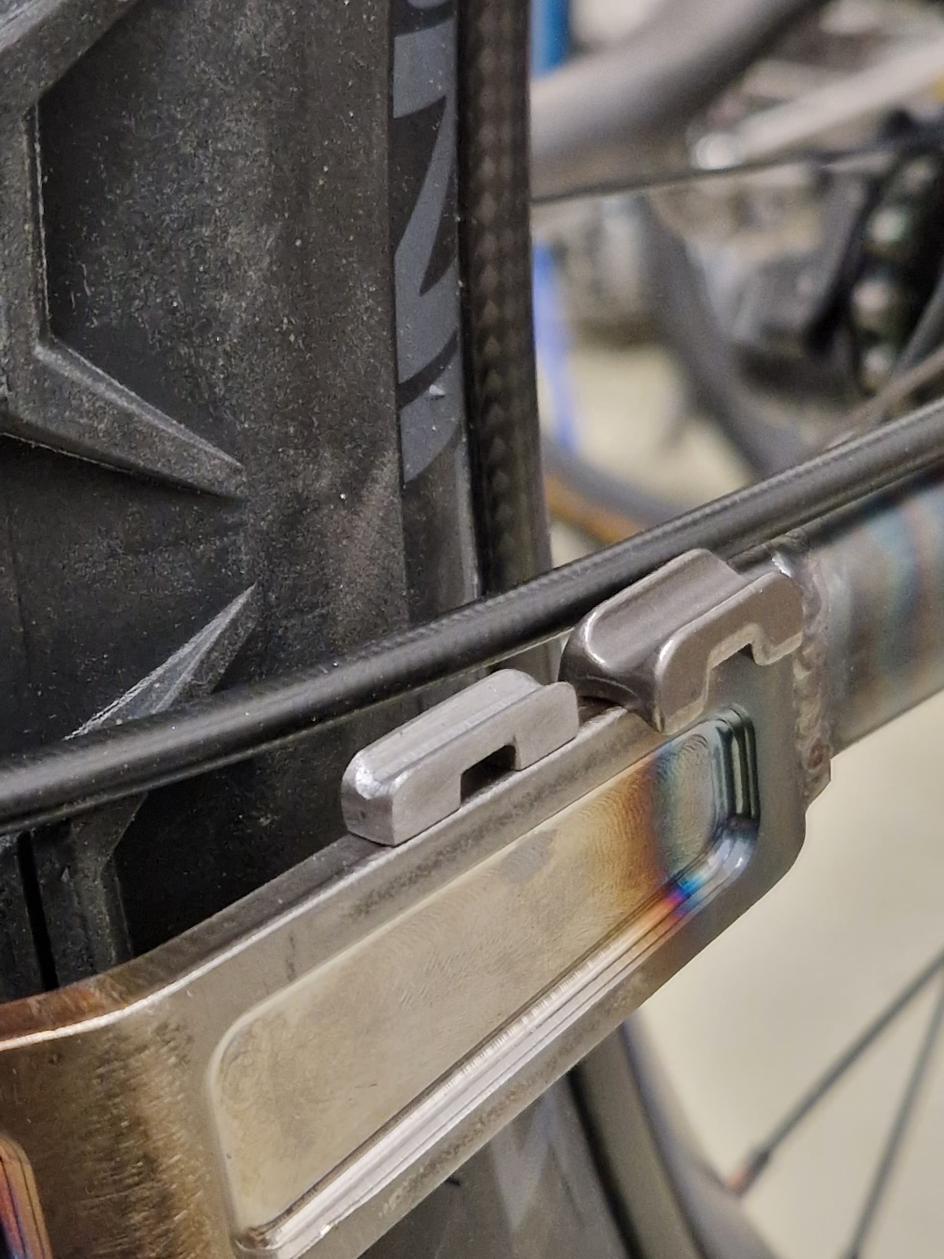
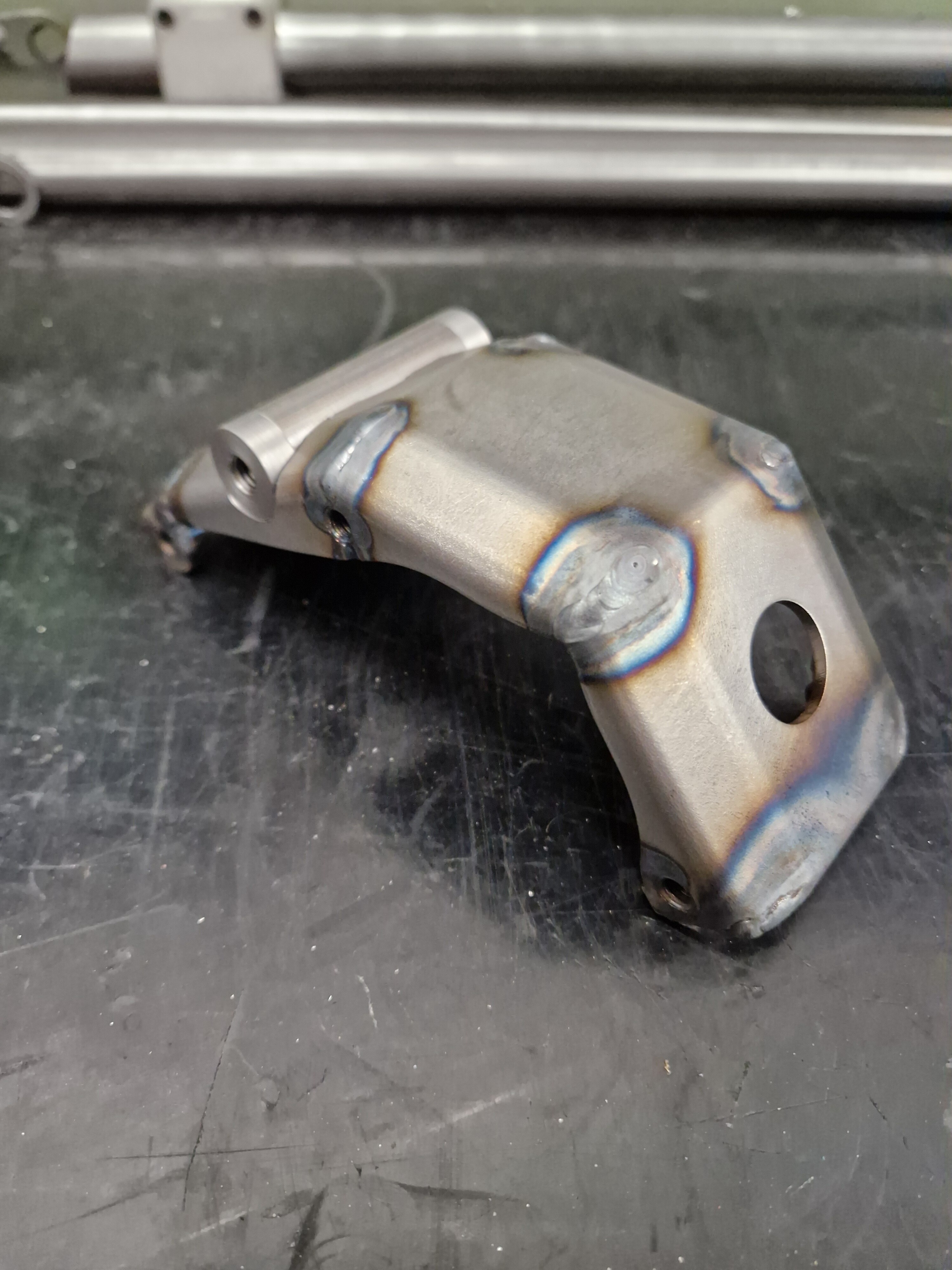
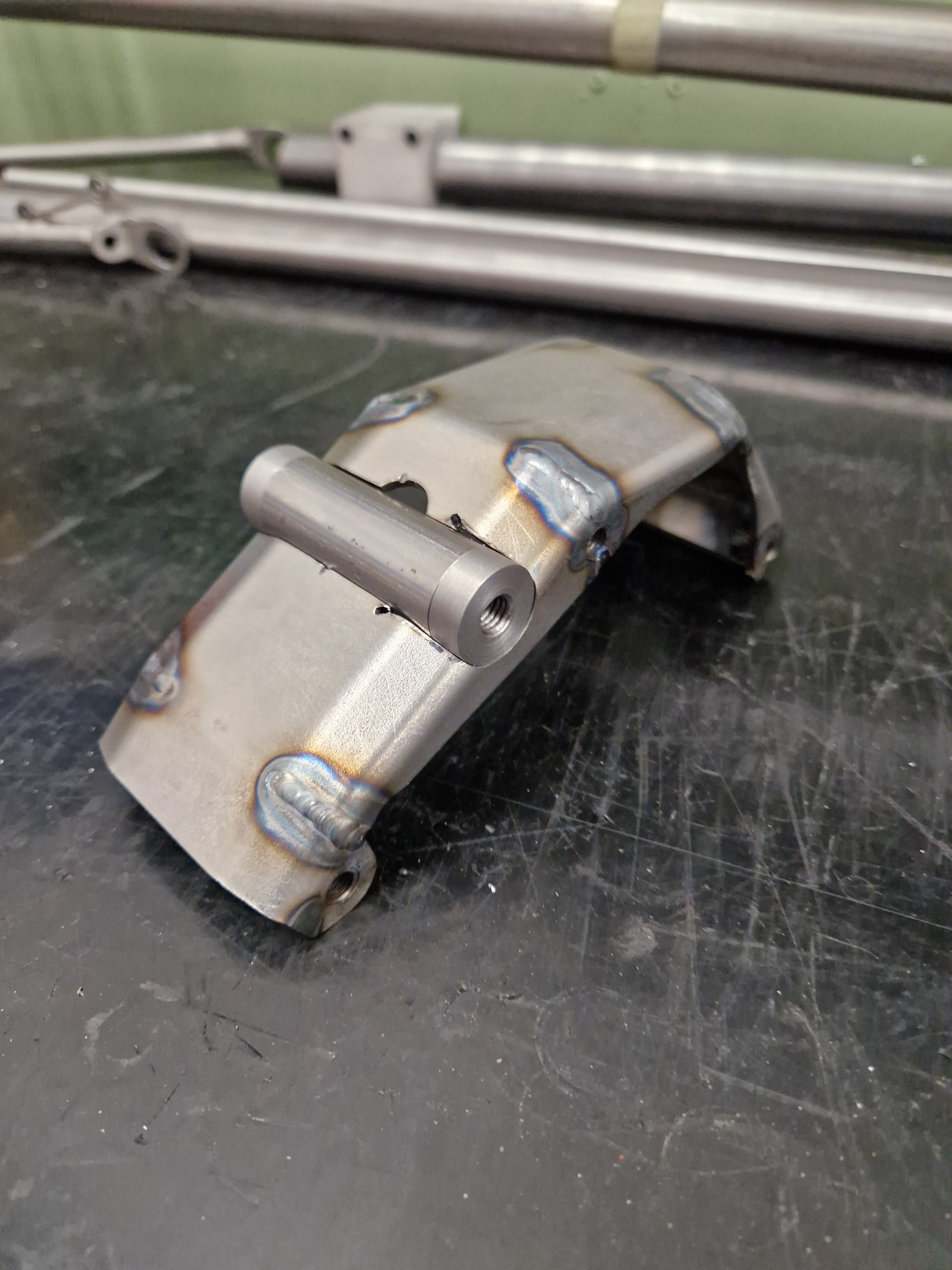
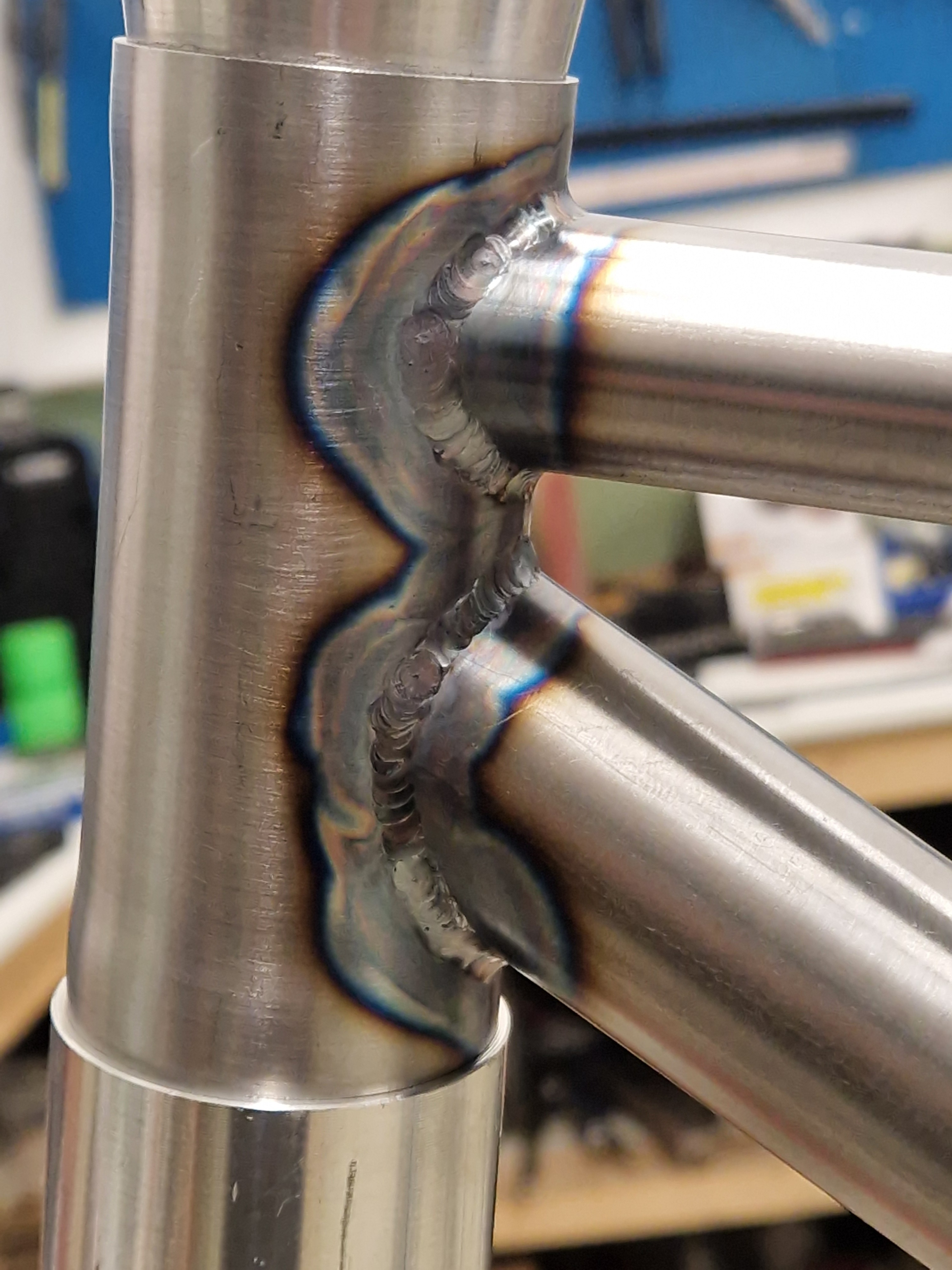
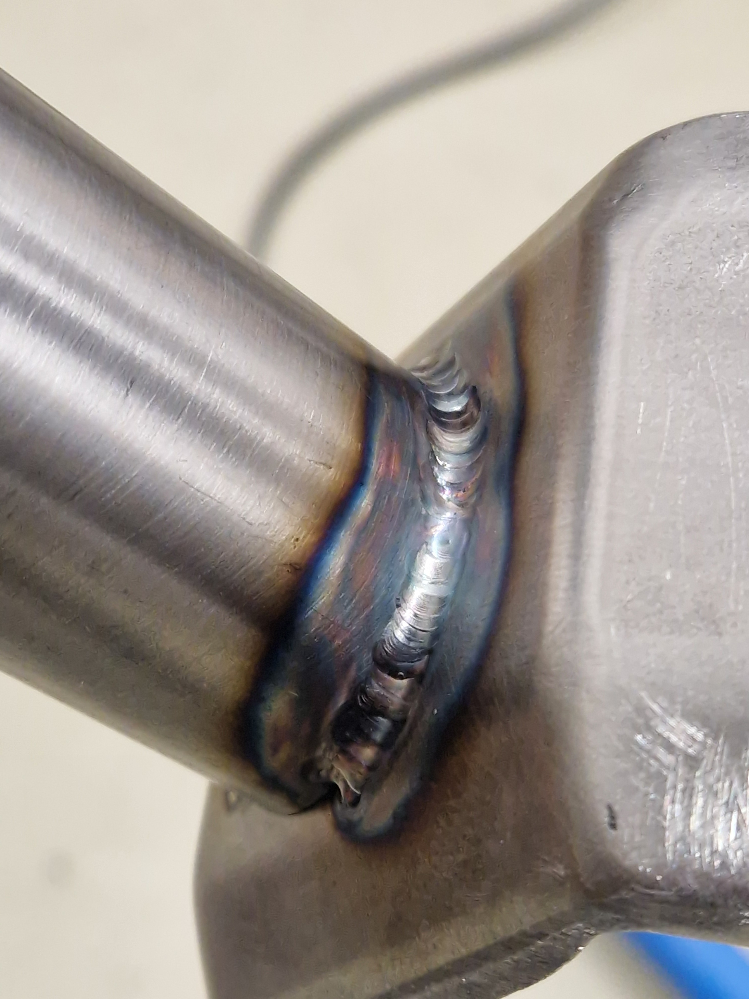
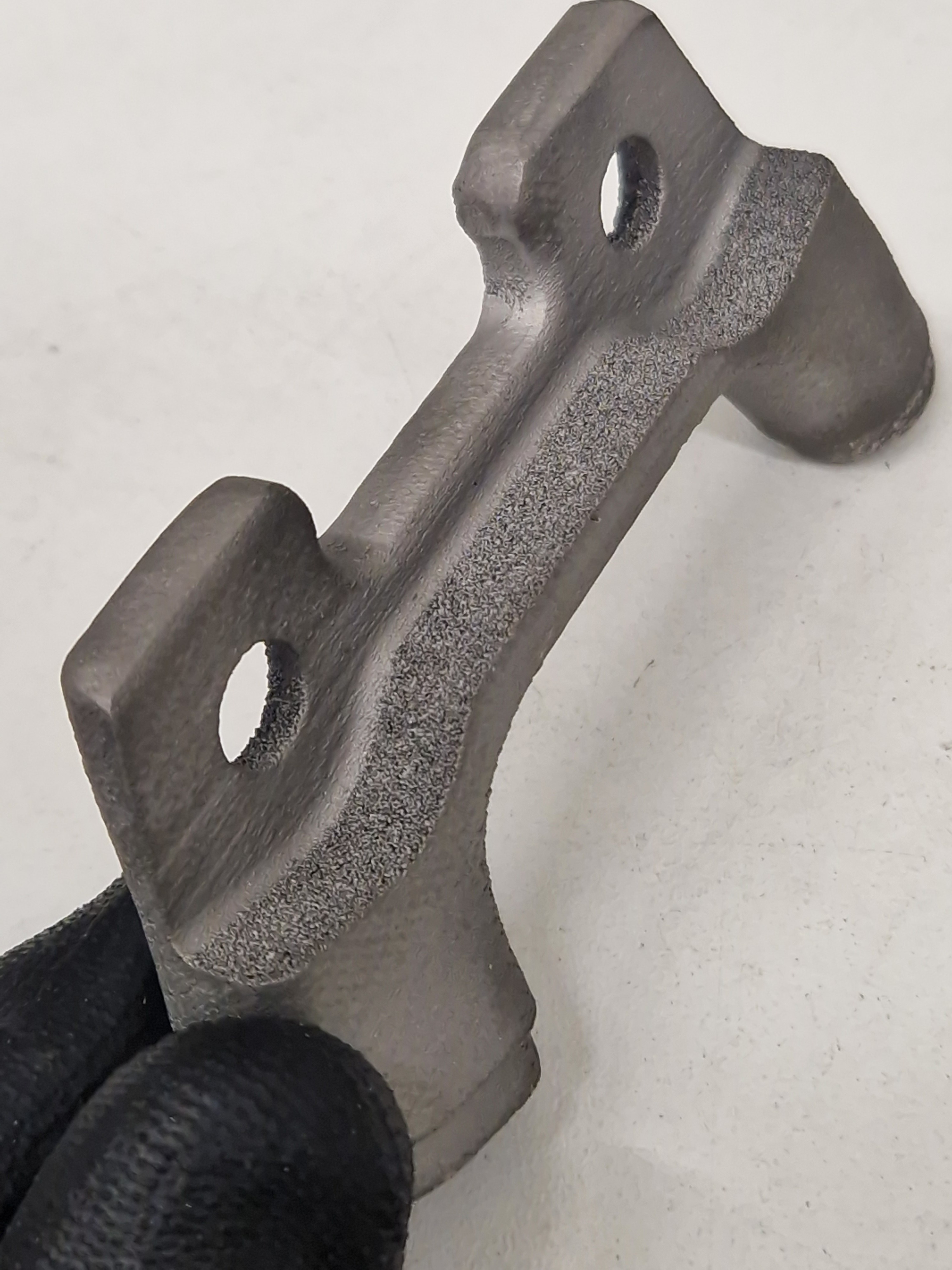
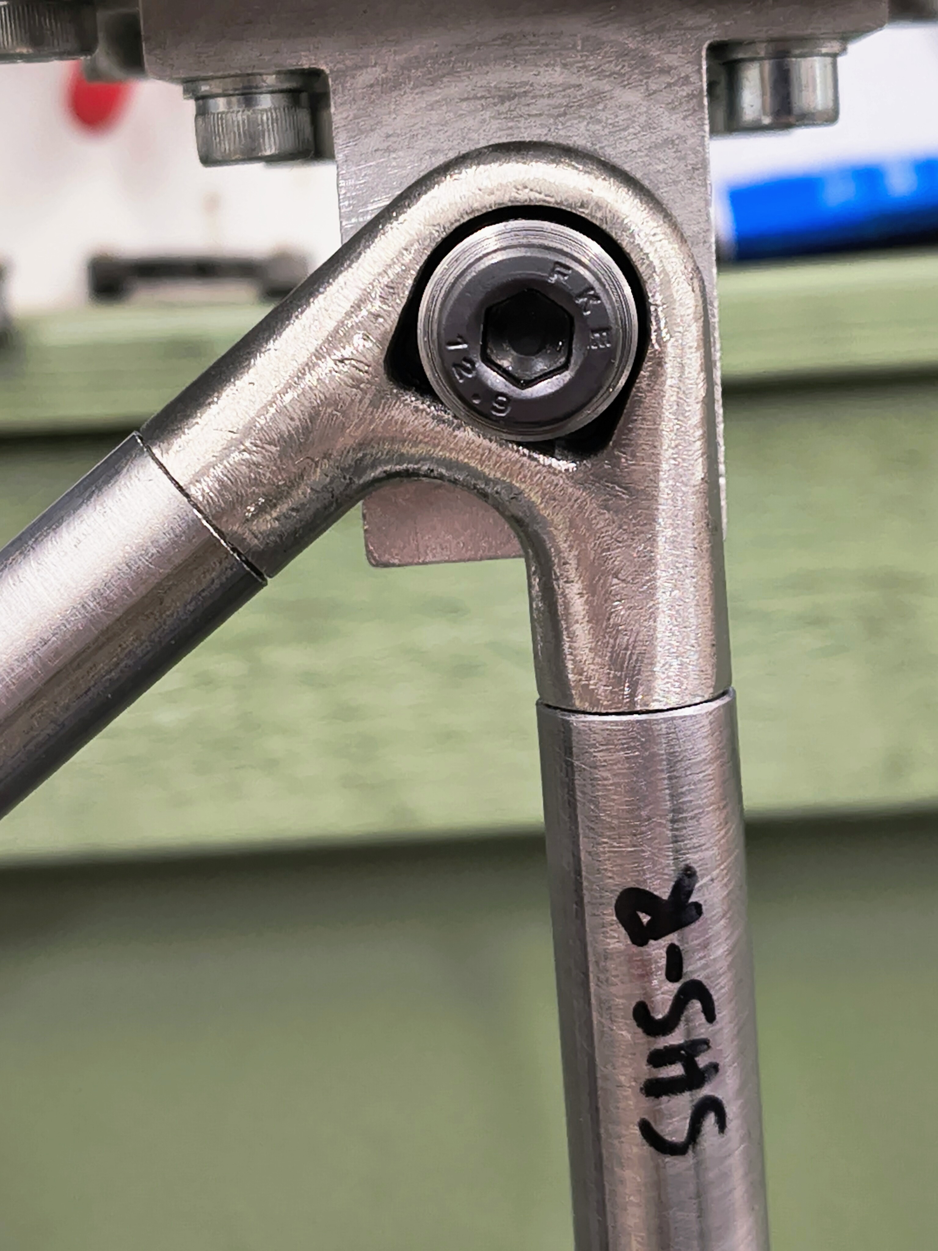
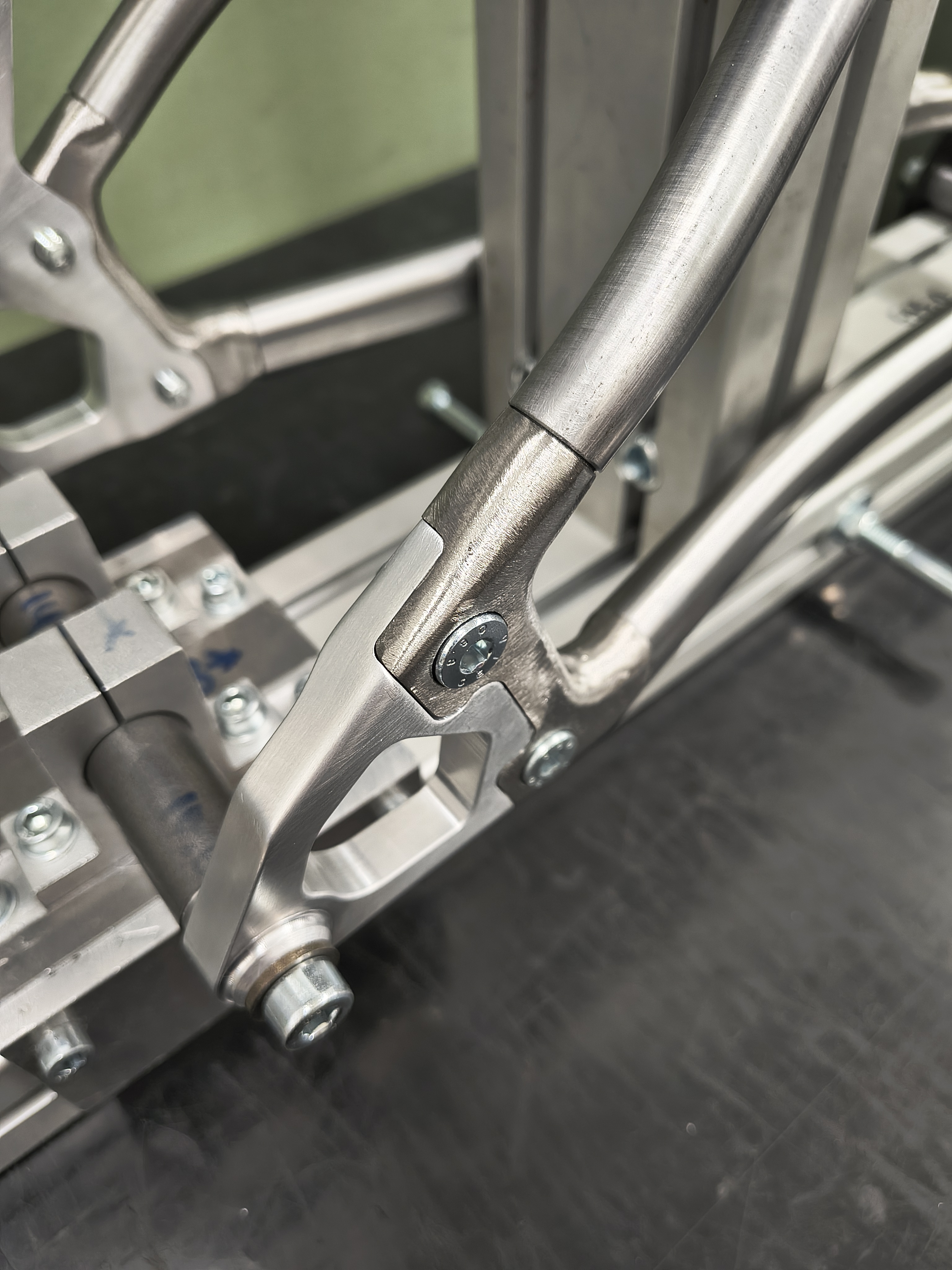
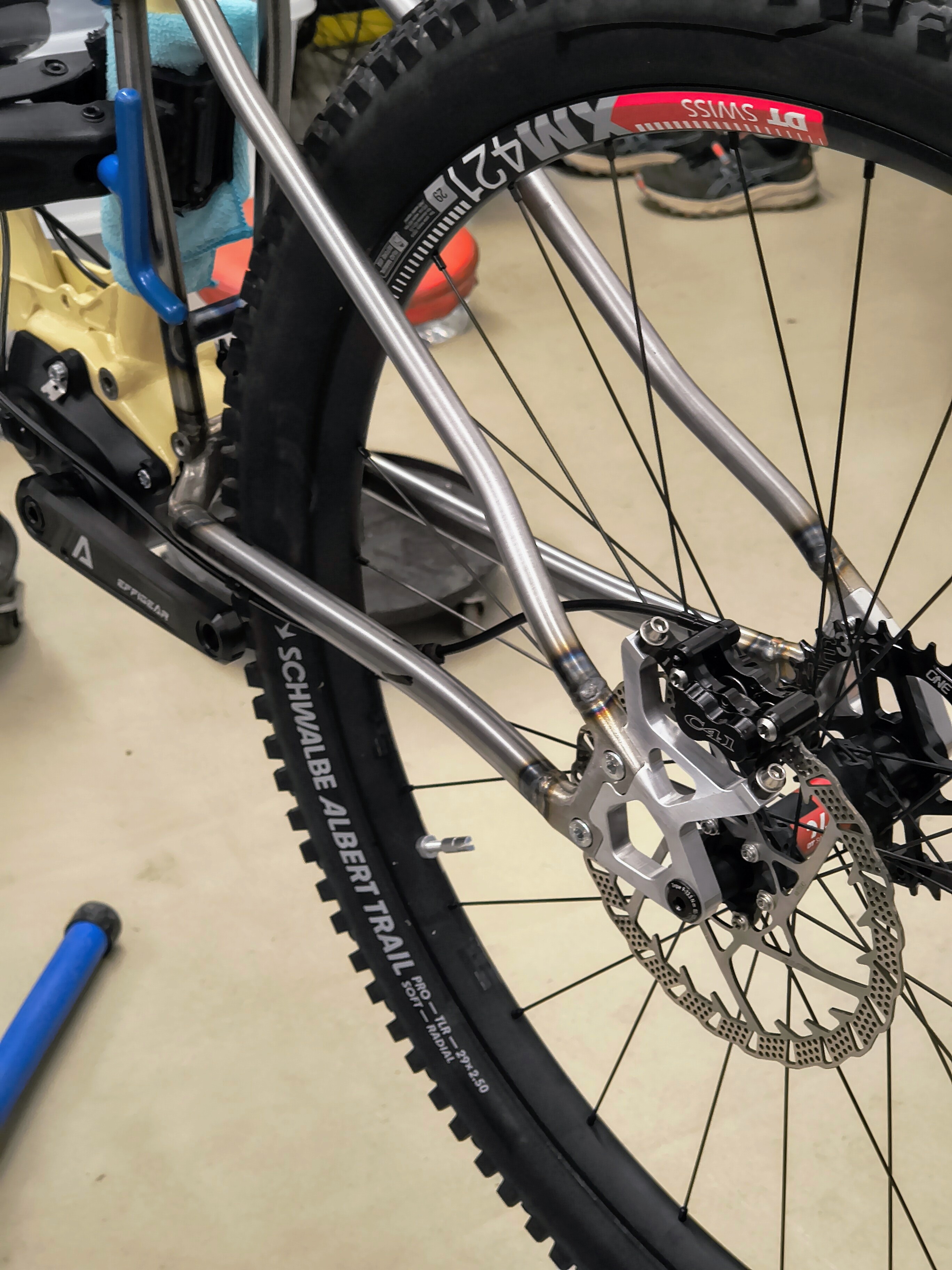
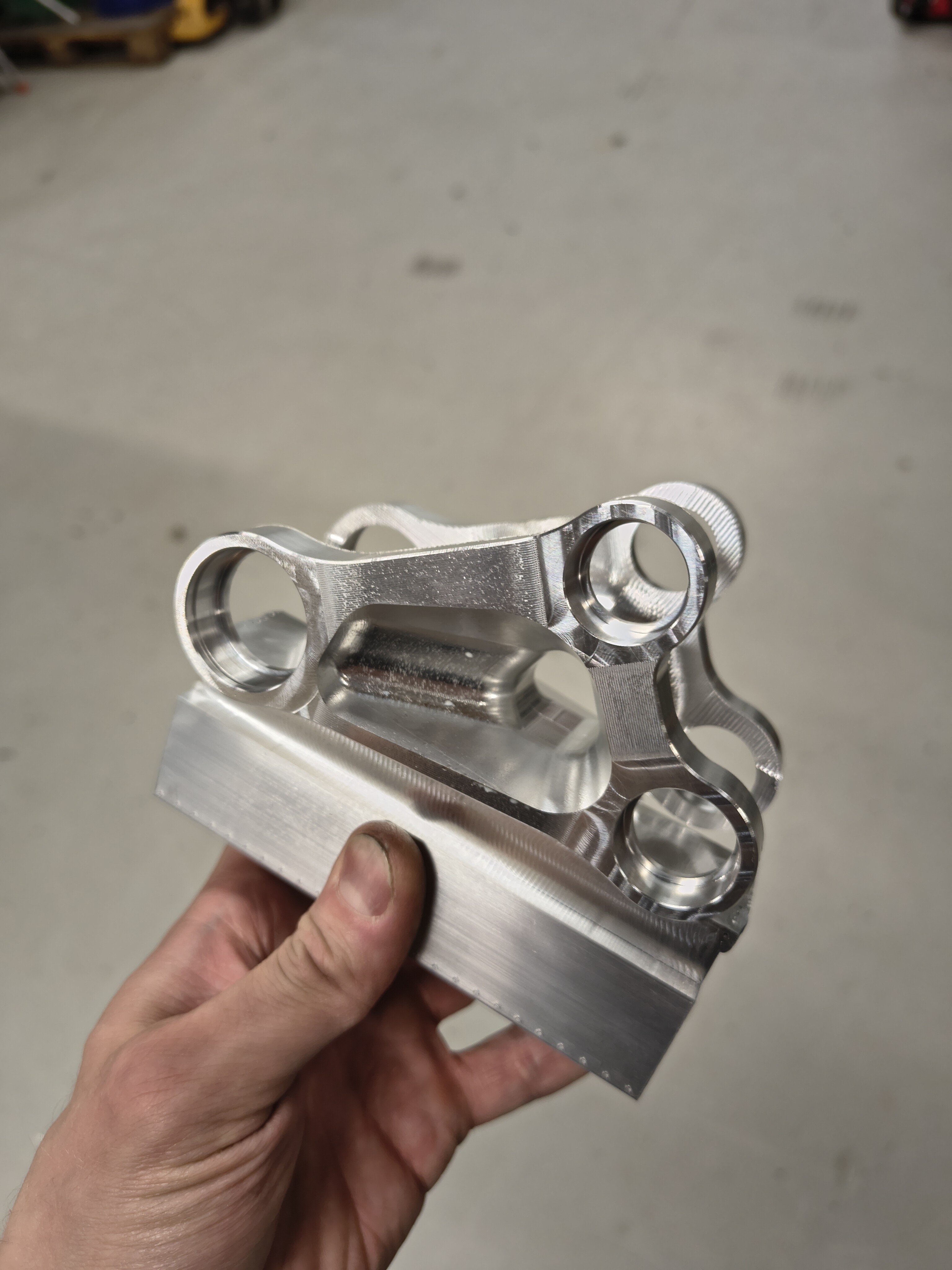
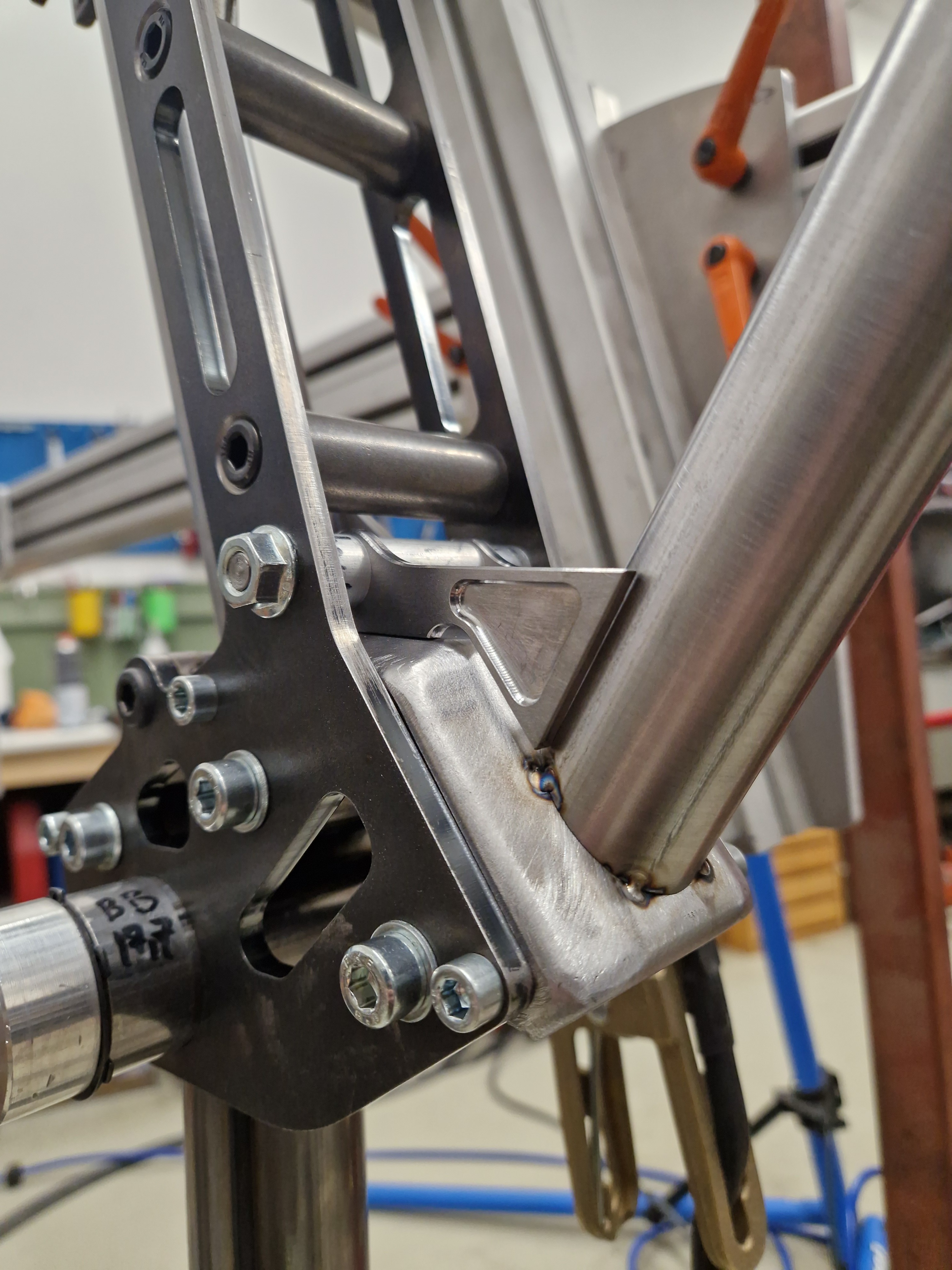
The modular design for dropout / brake mount.

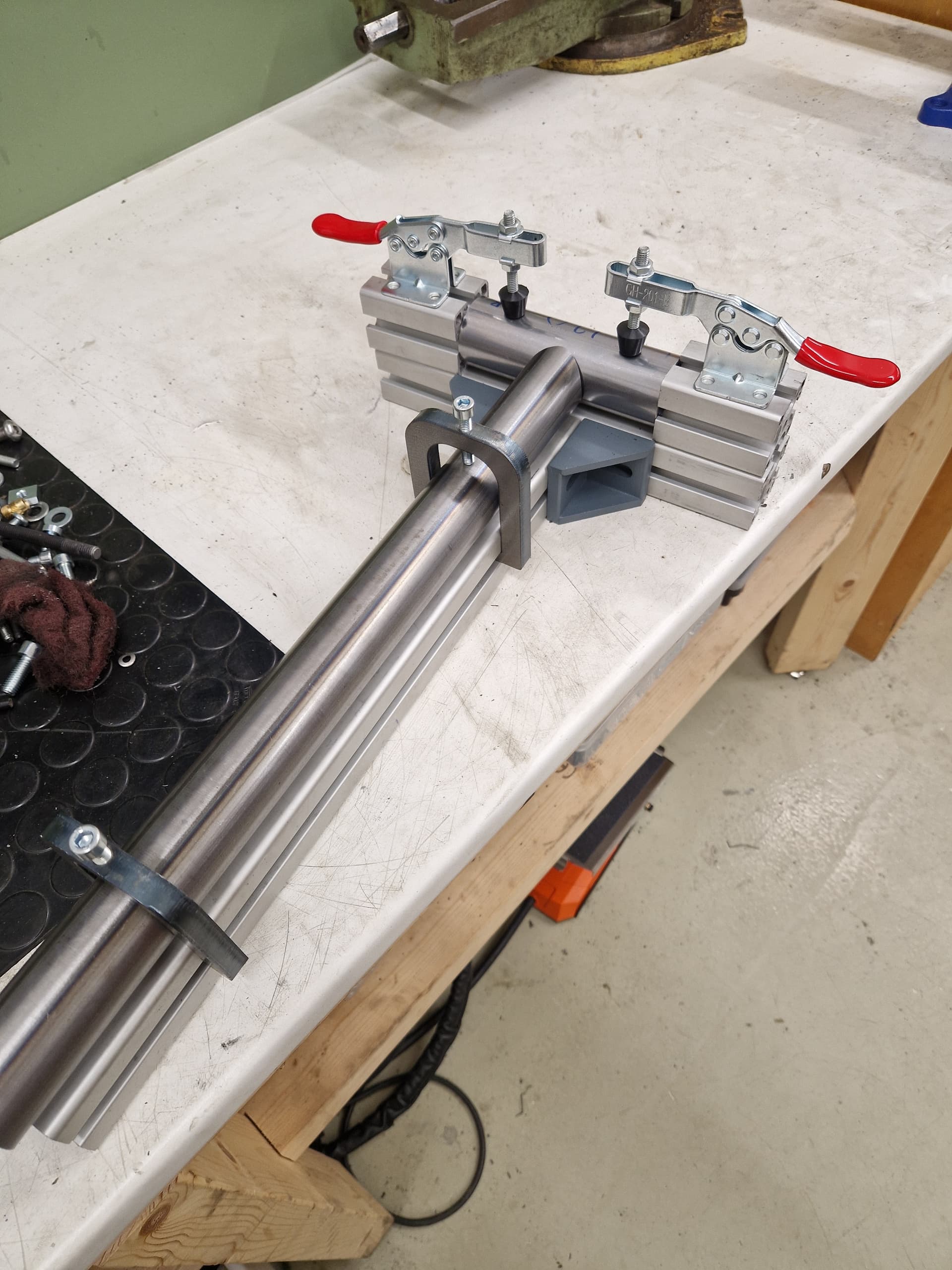
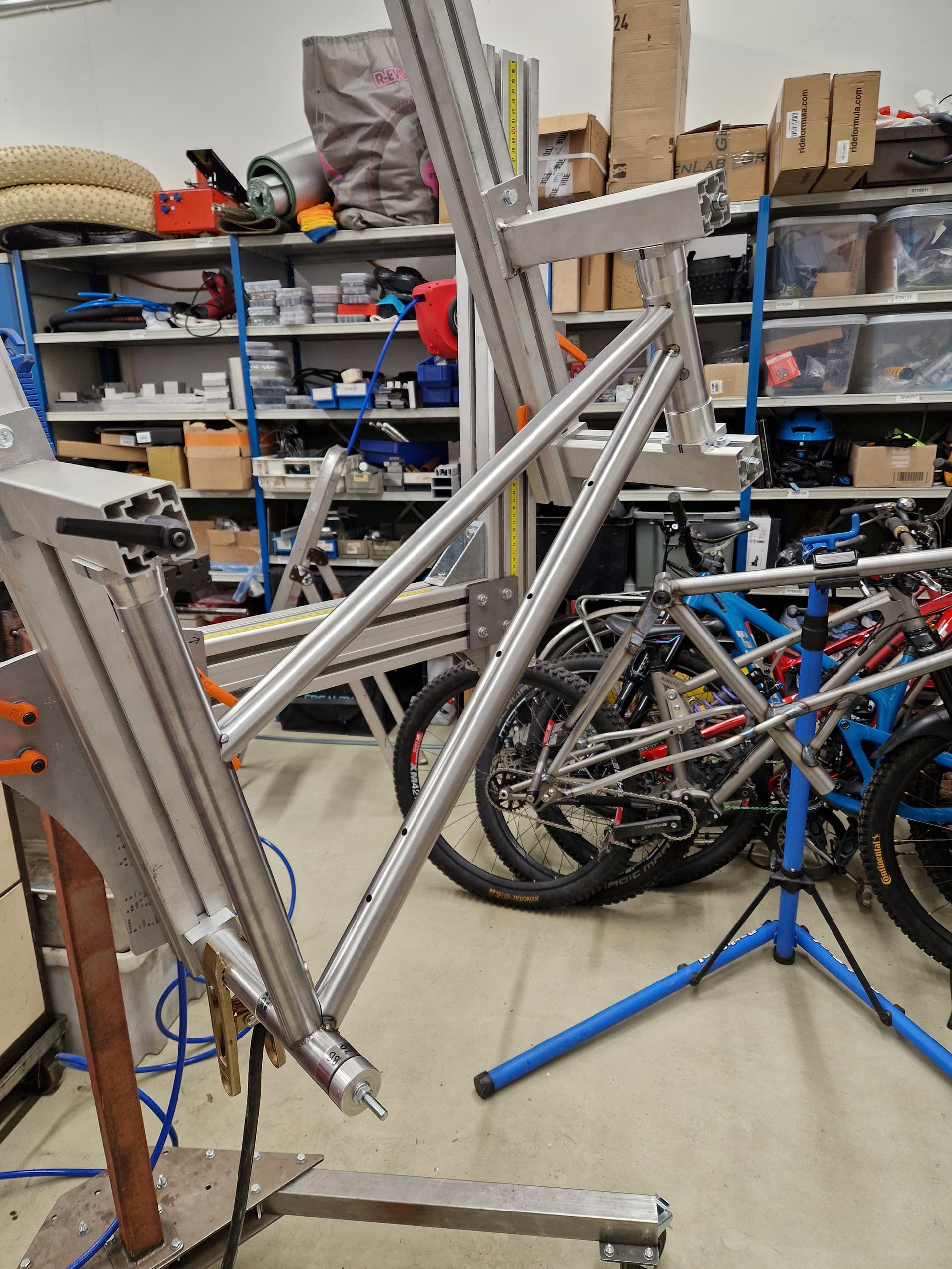
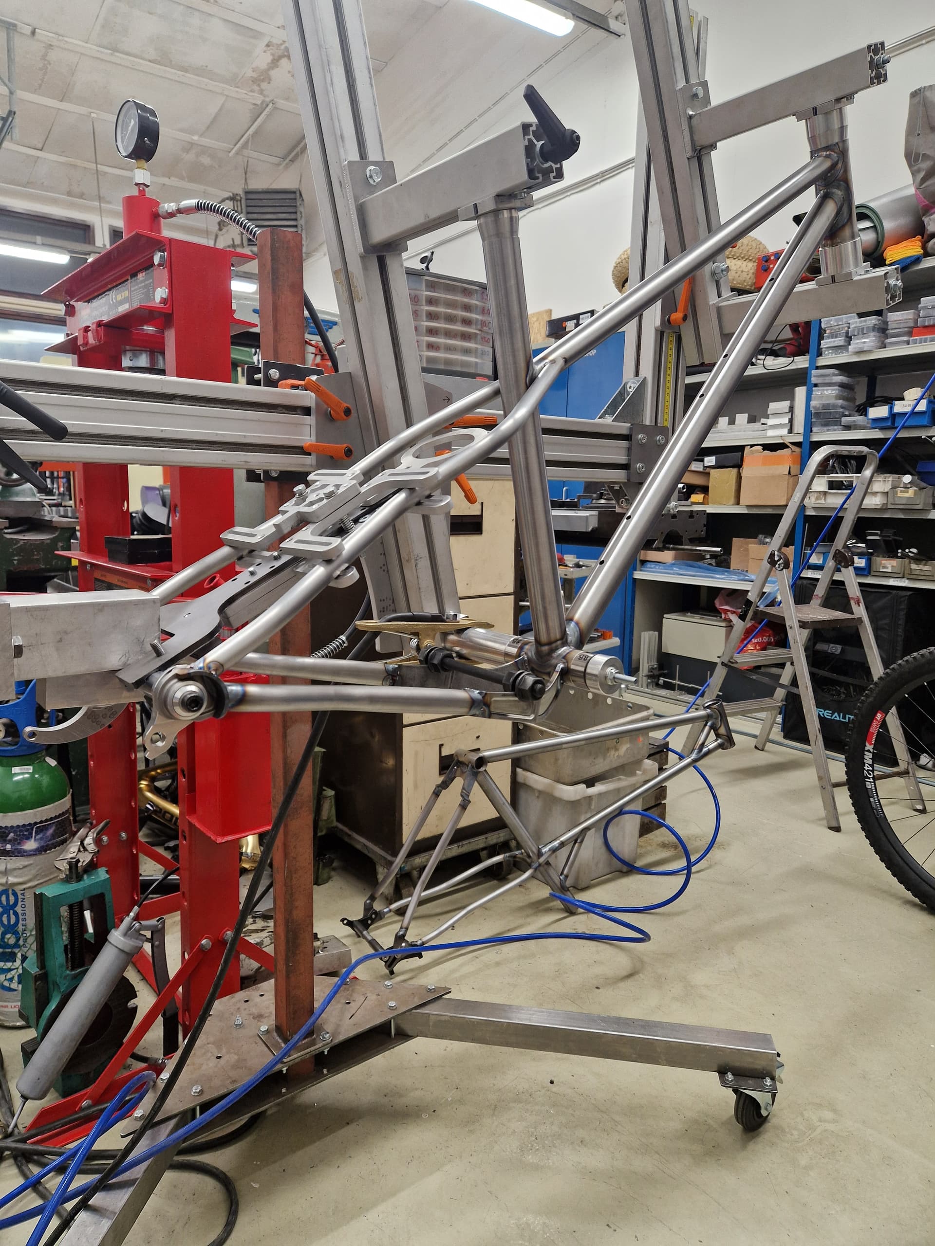
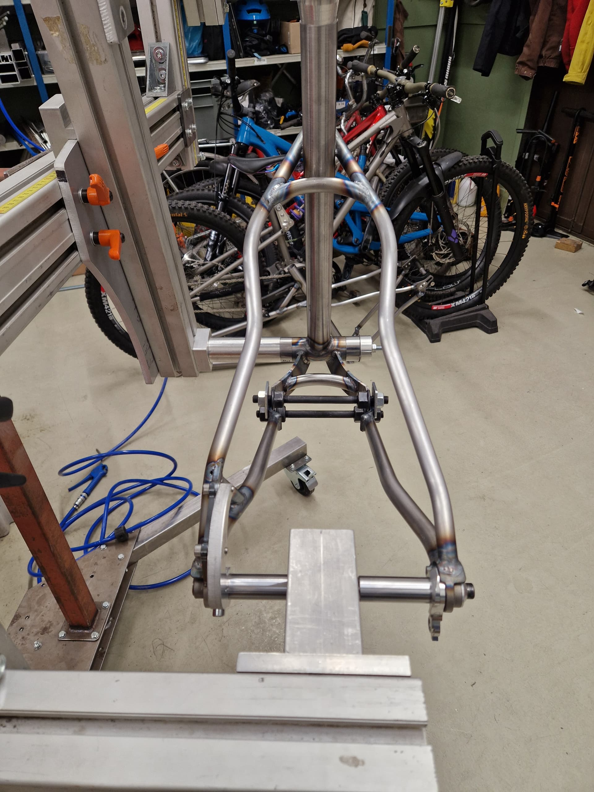
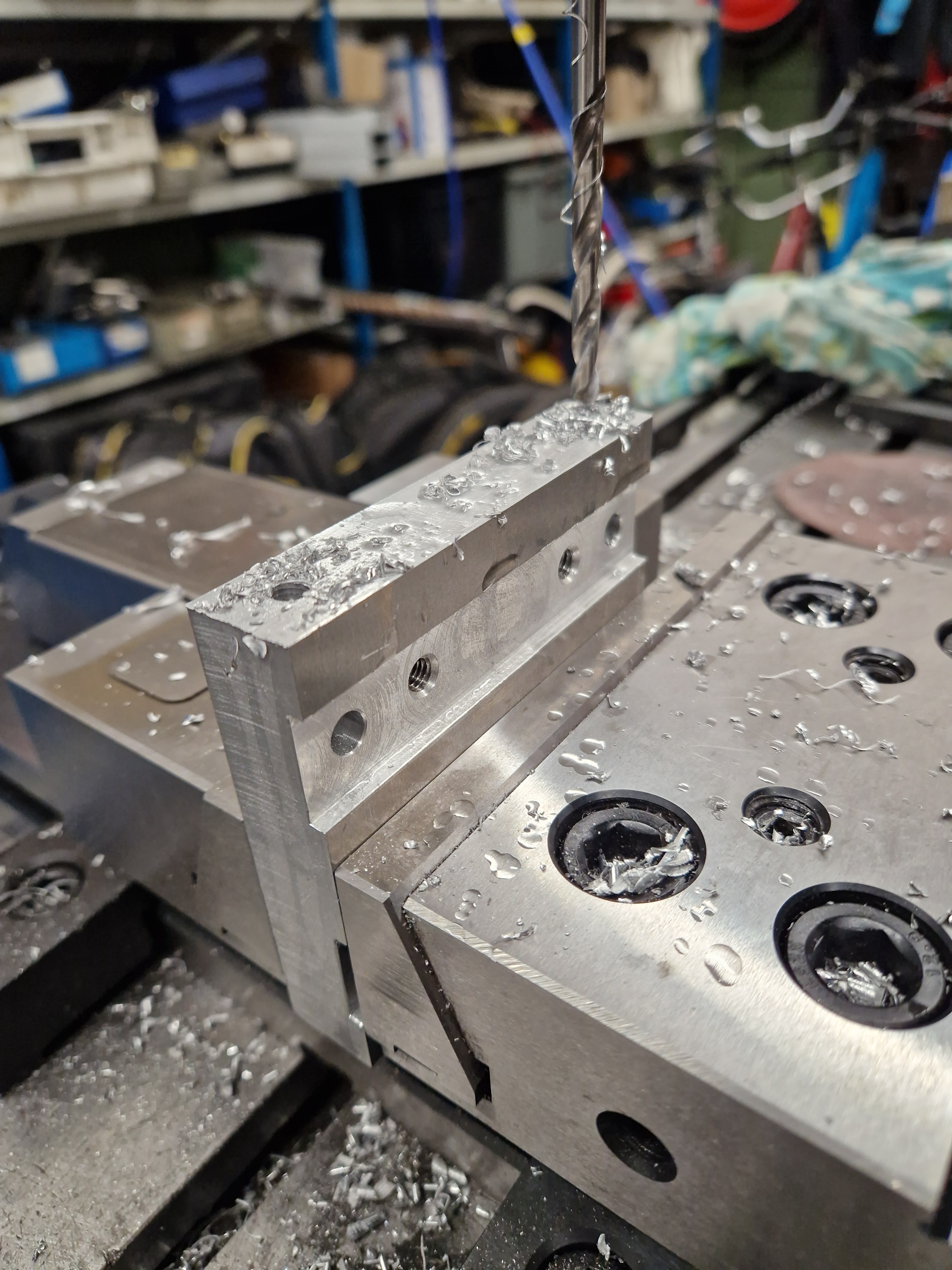
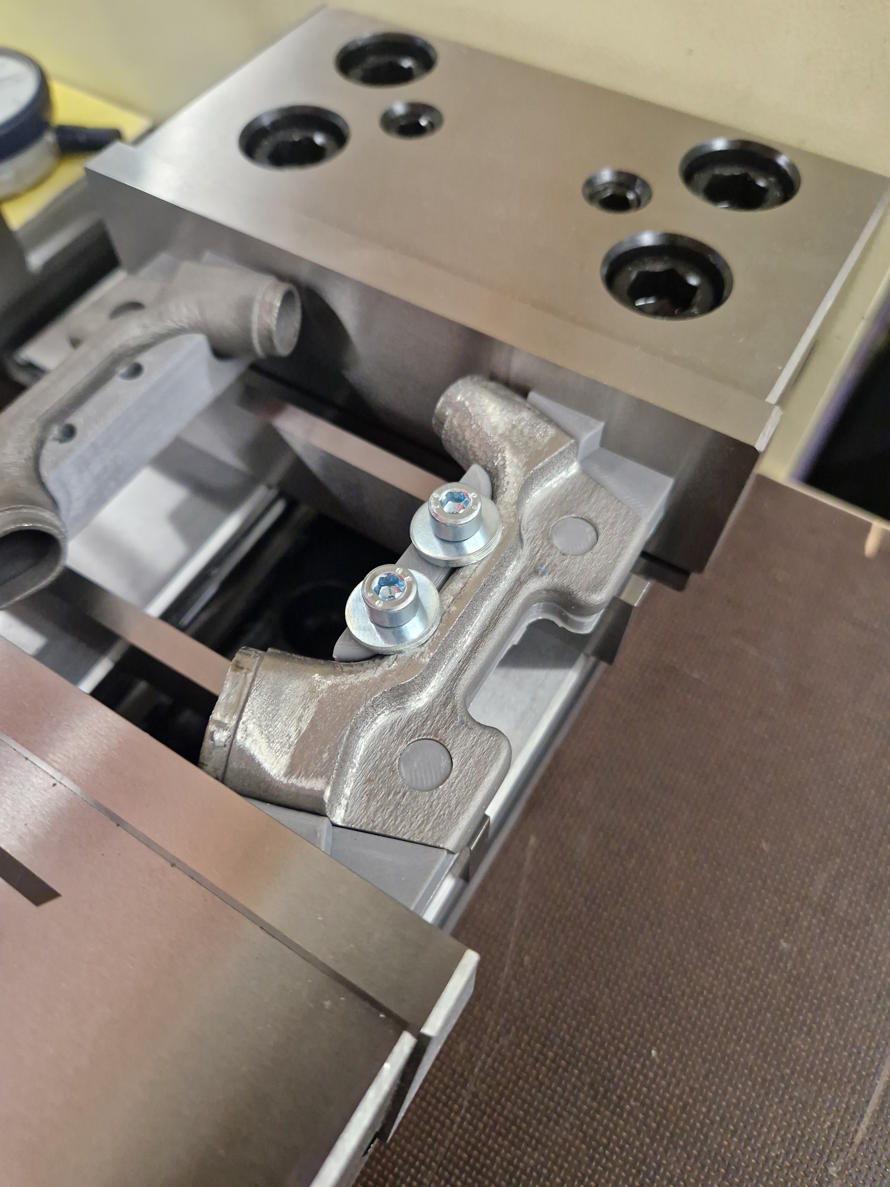
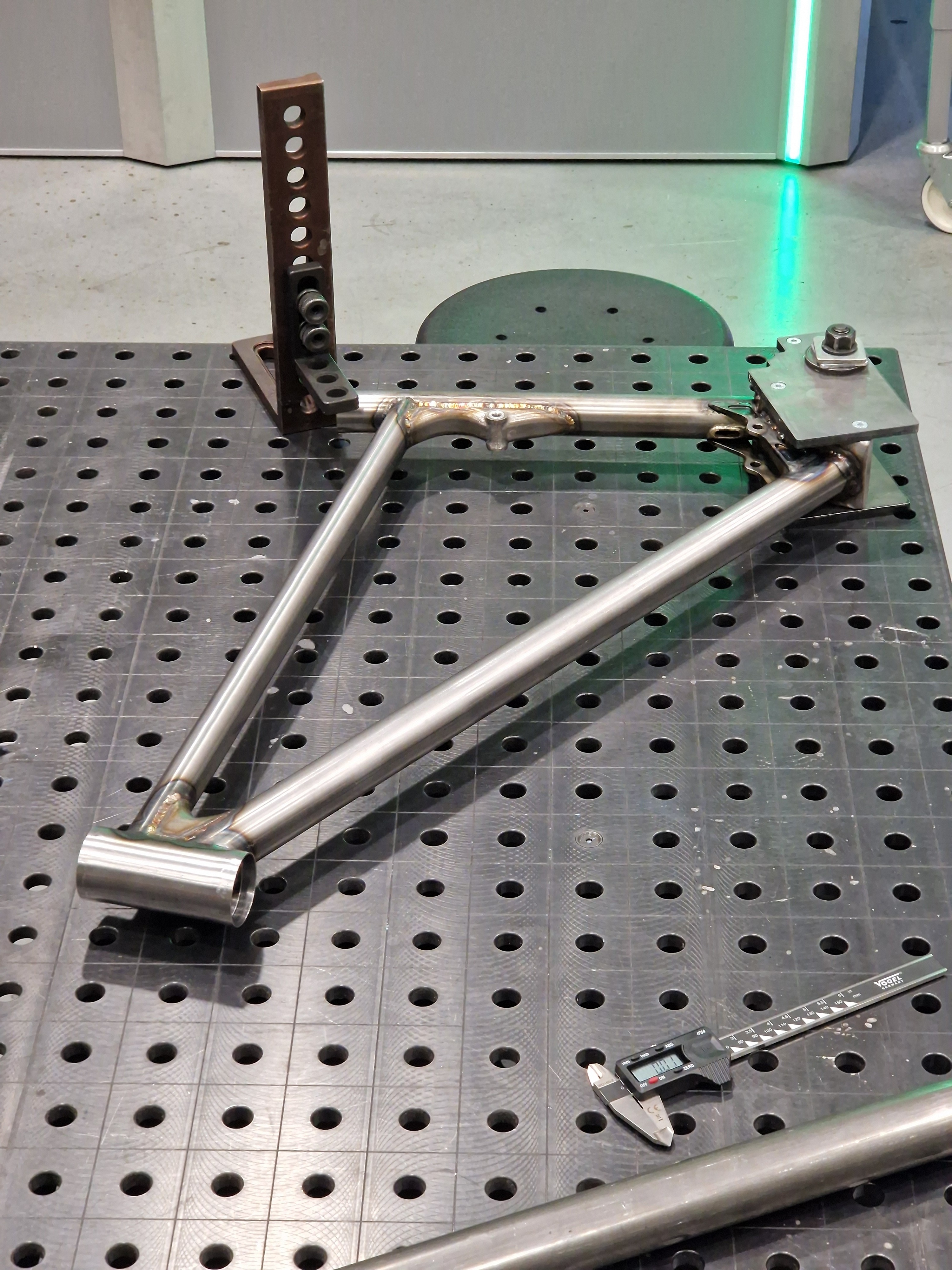
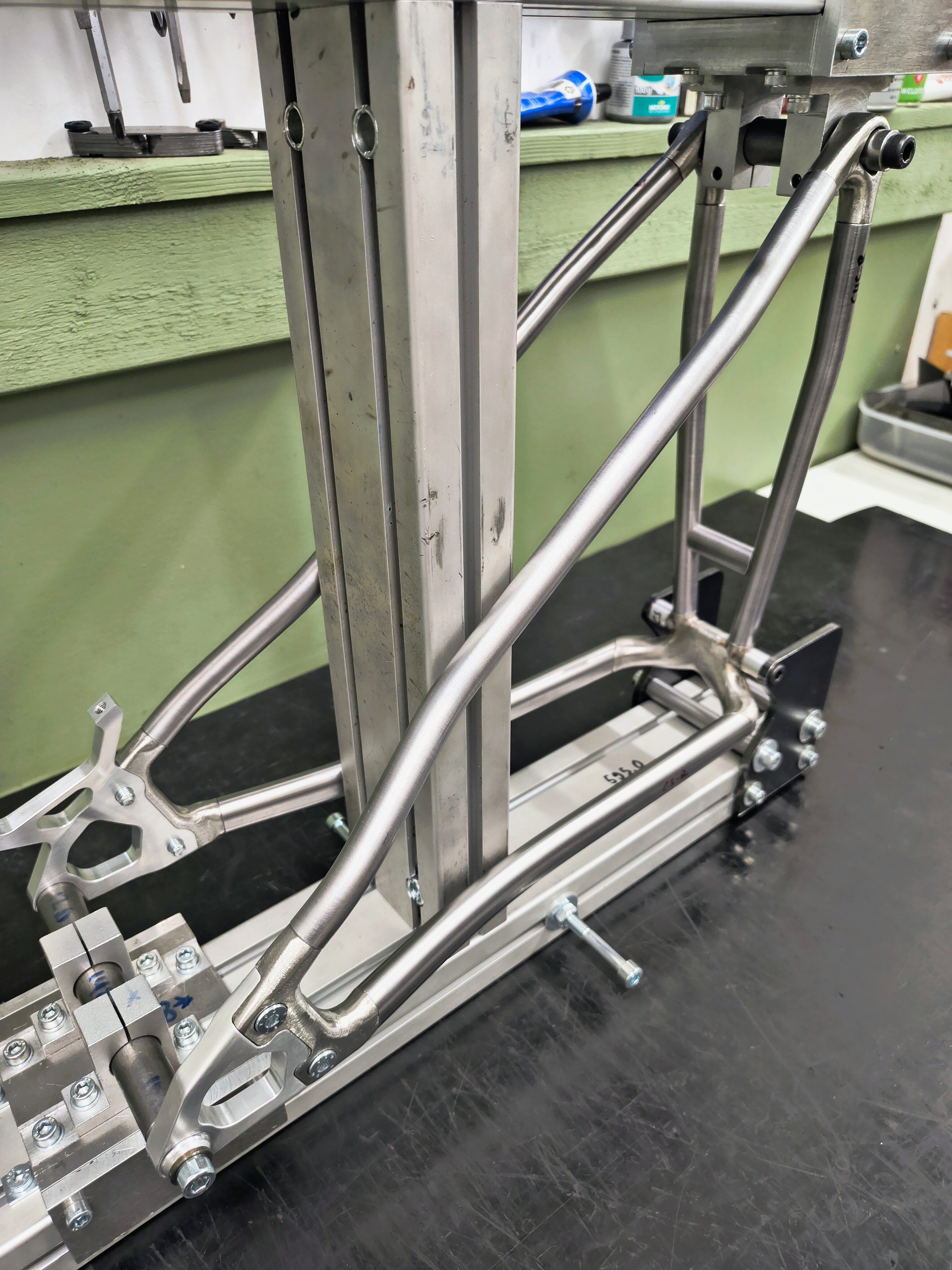
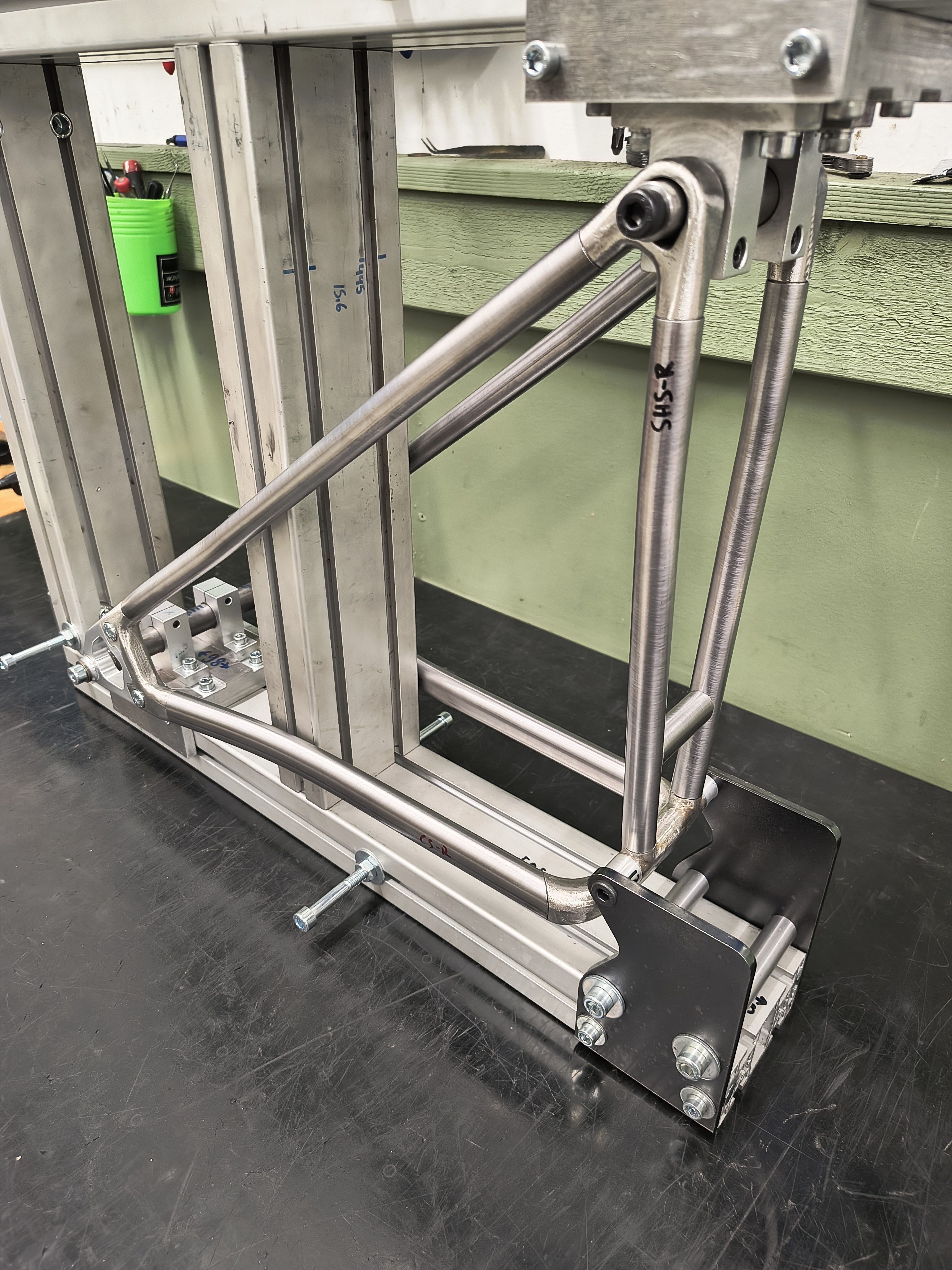
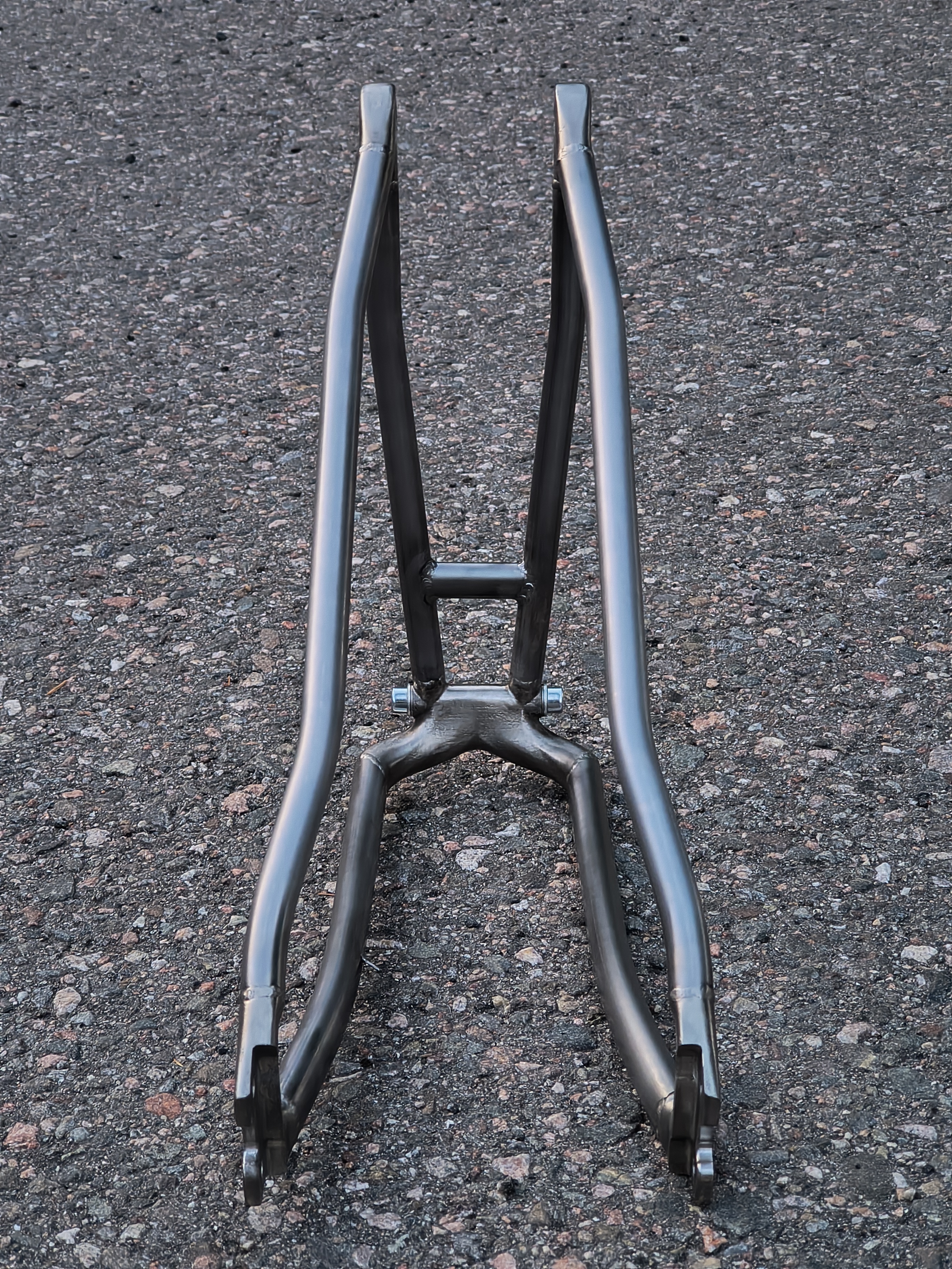
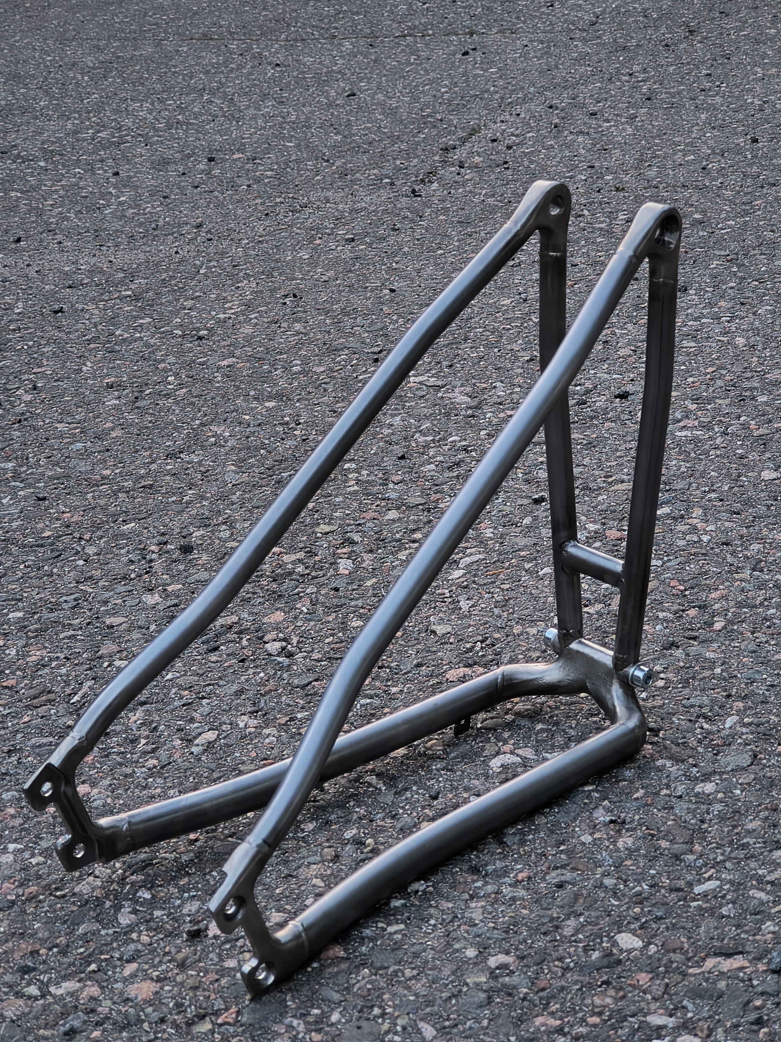
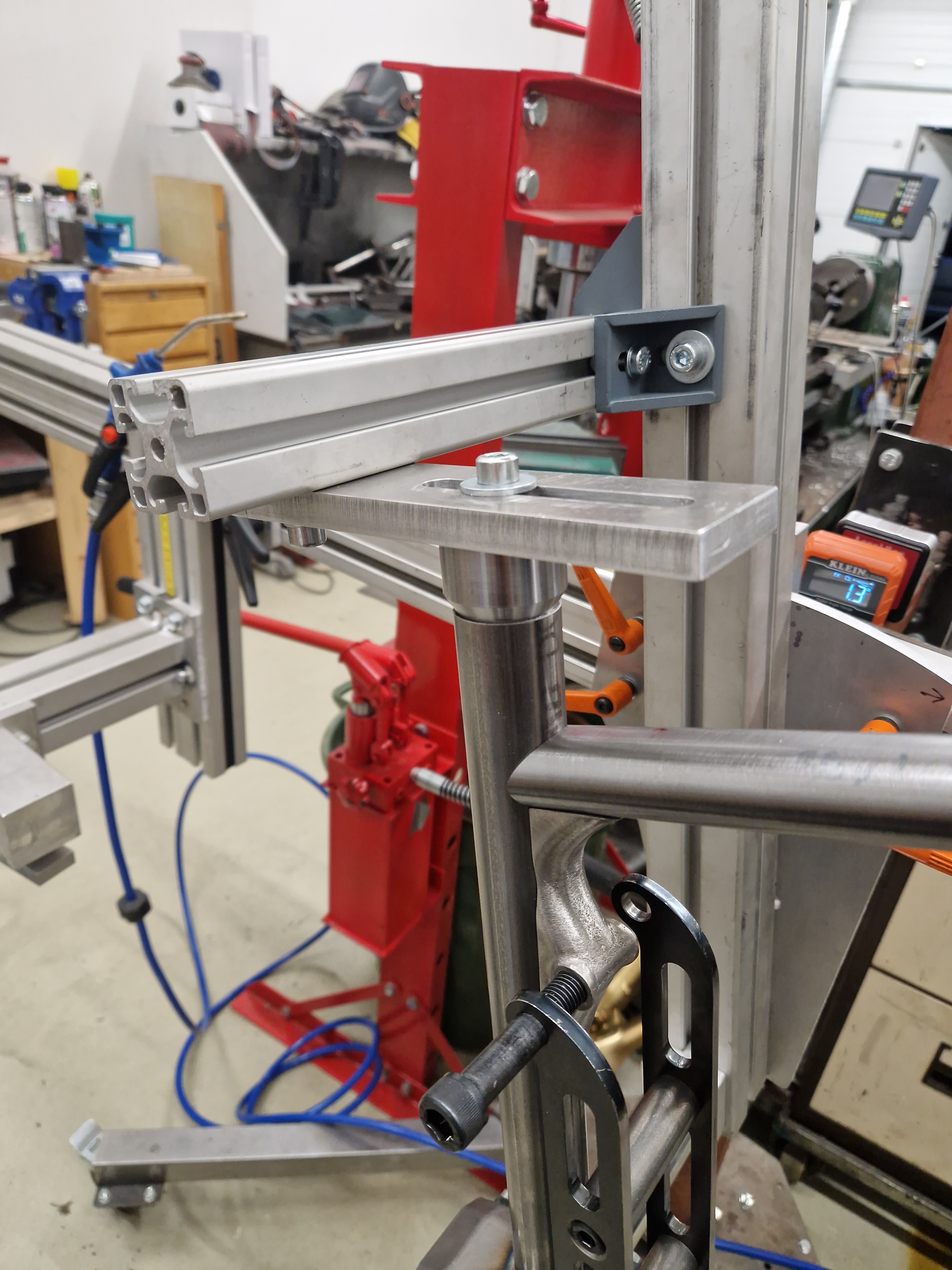
Made somewhat adjustable rear triangle fixture.

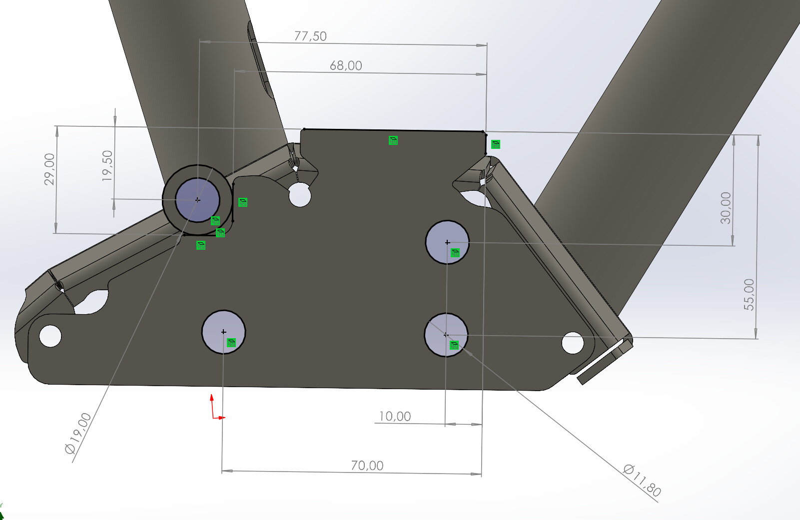
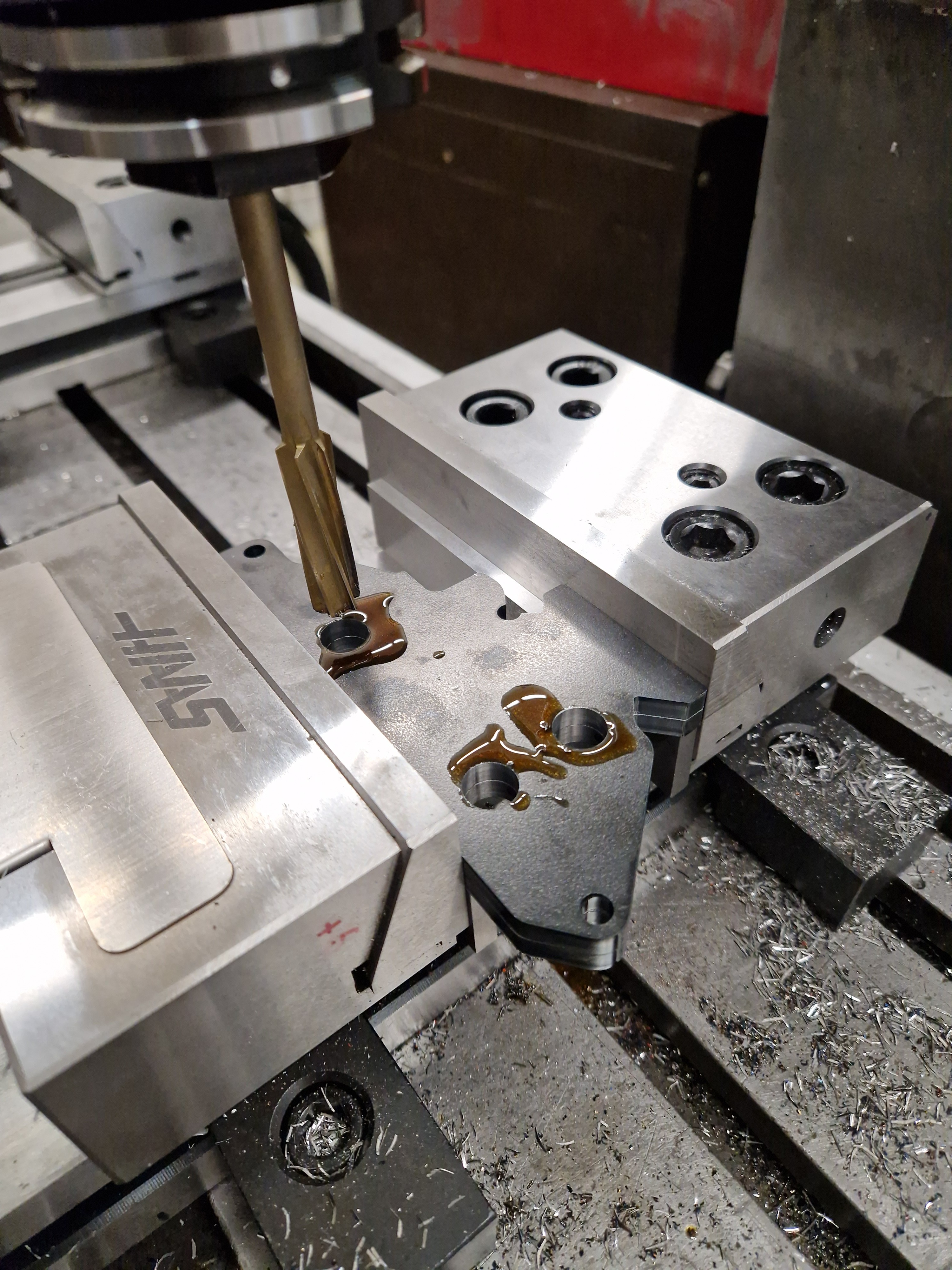
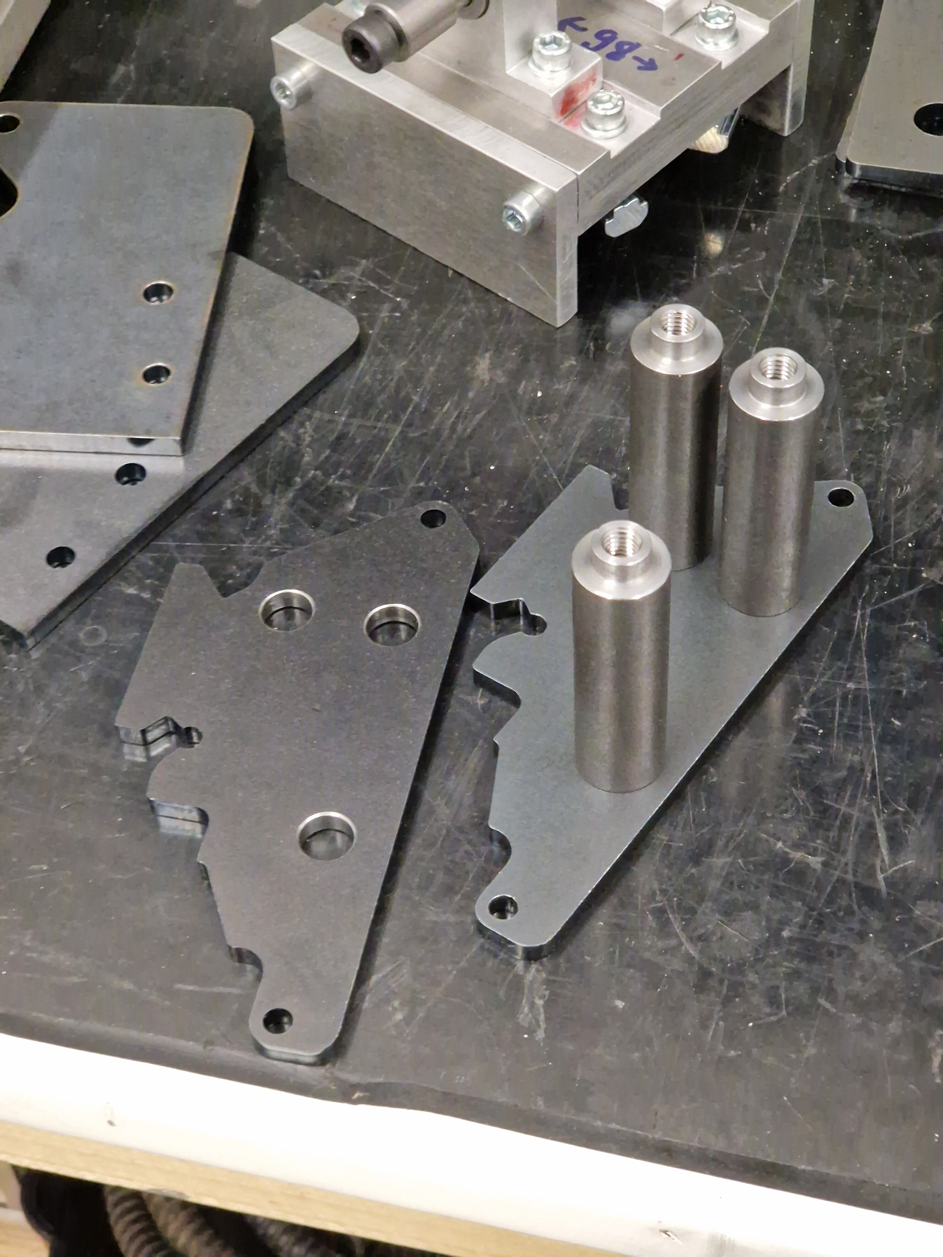
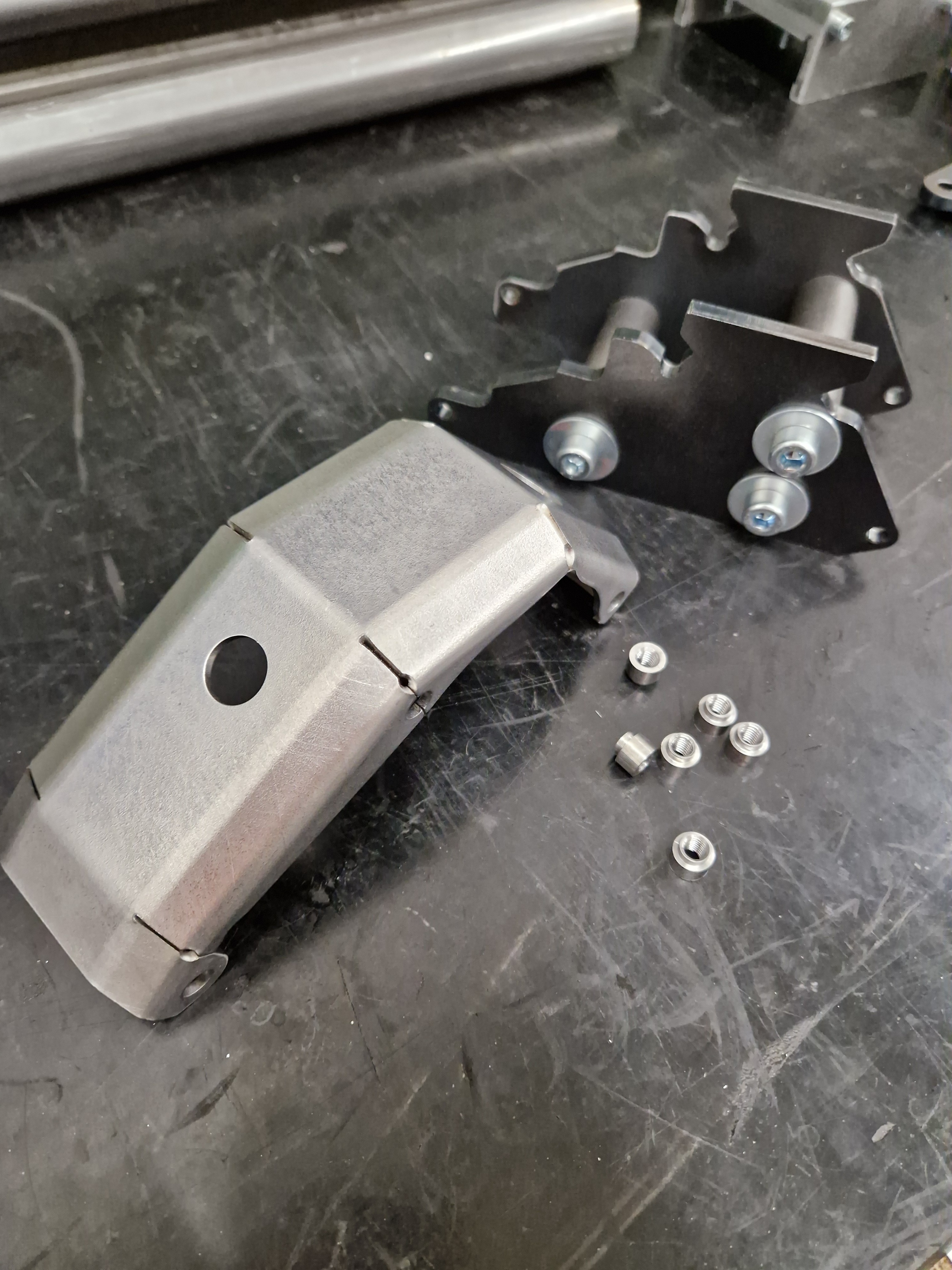
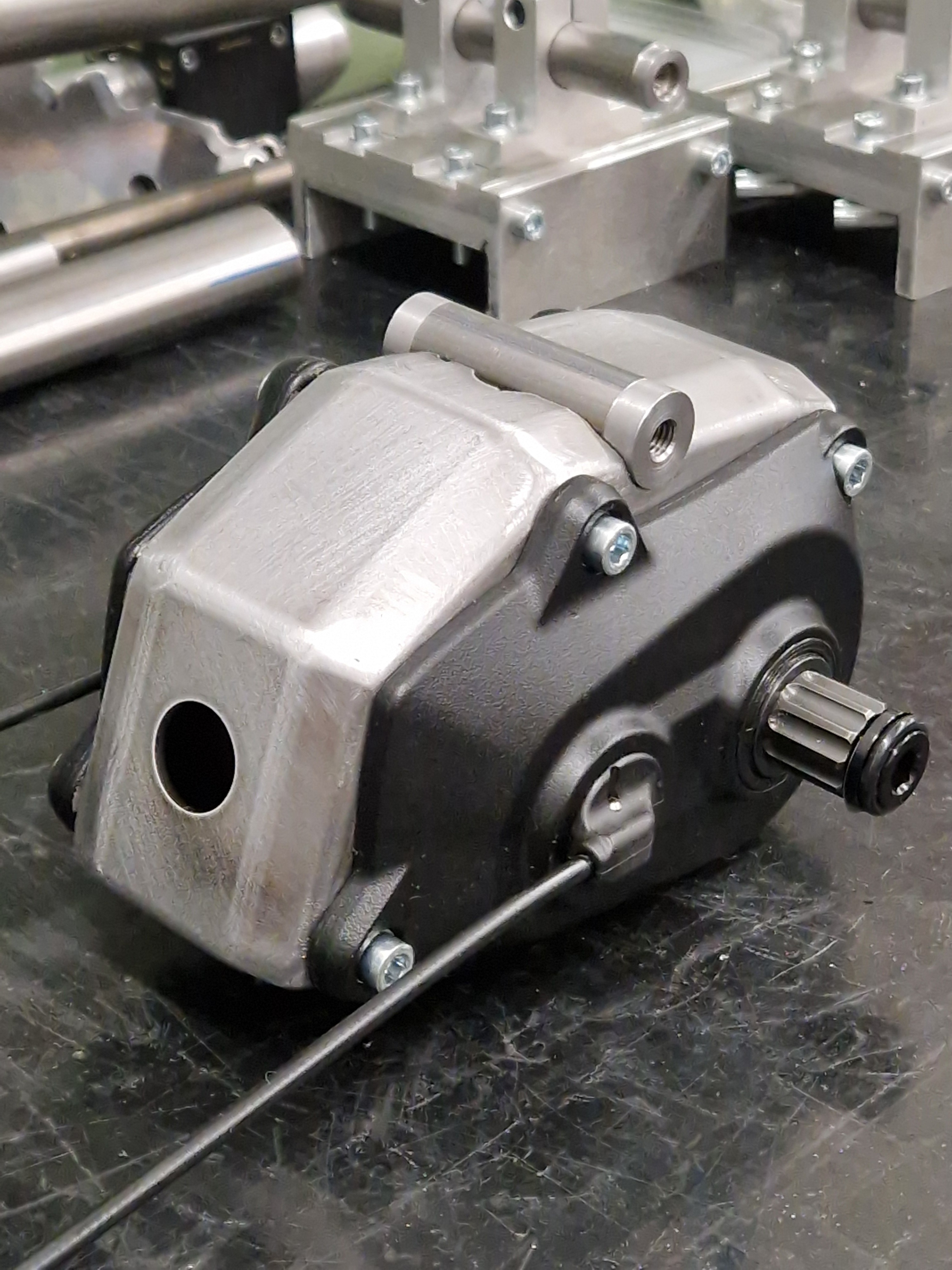
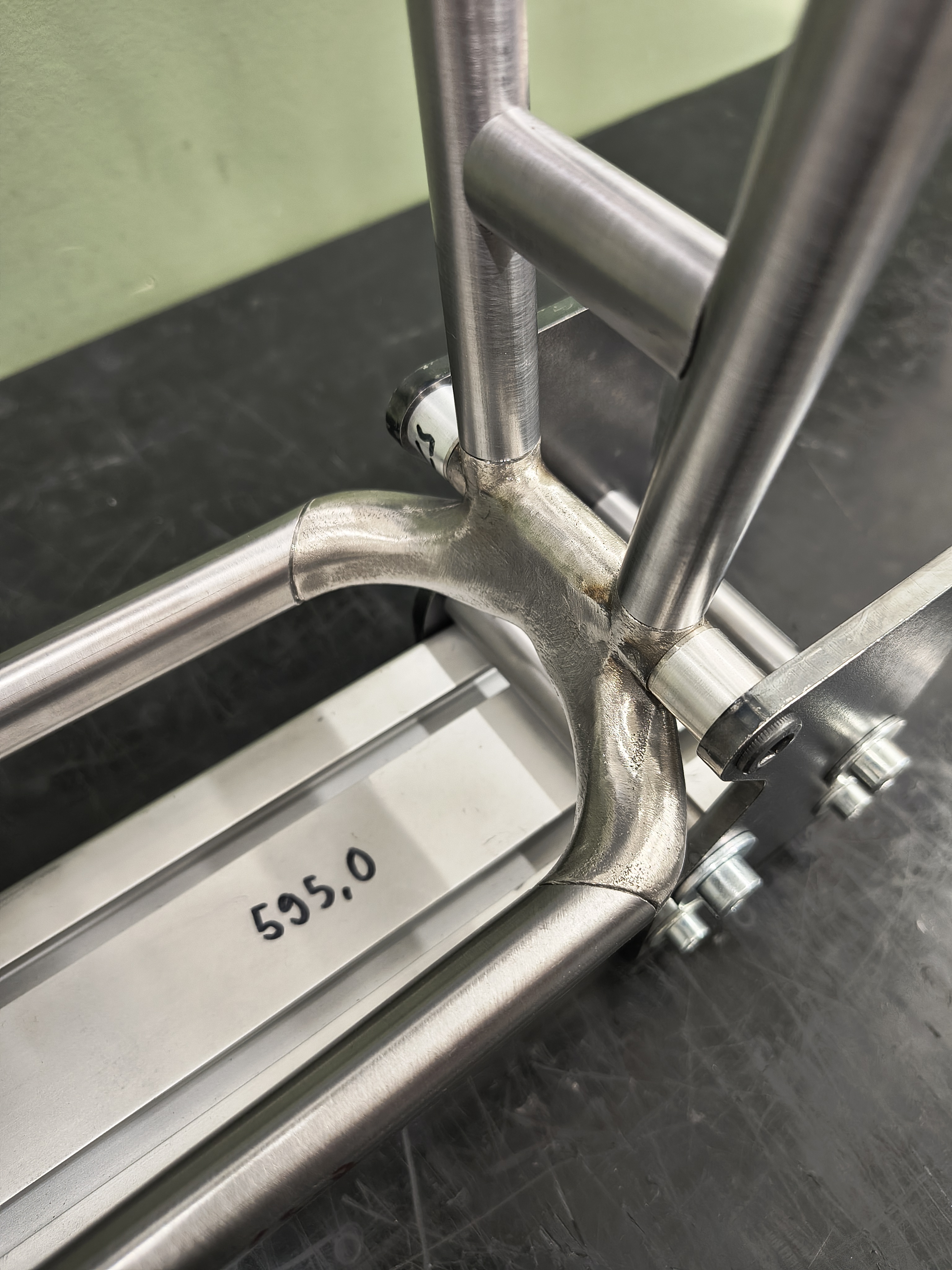
Fixtures for gearbox bridge.

Lasercut and brake pressed bridge going for the welding fixture.

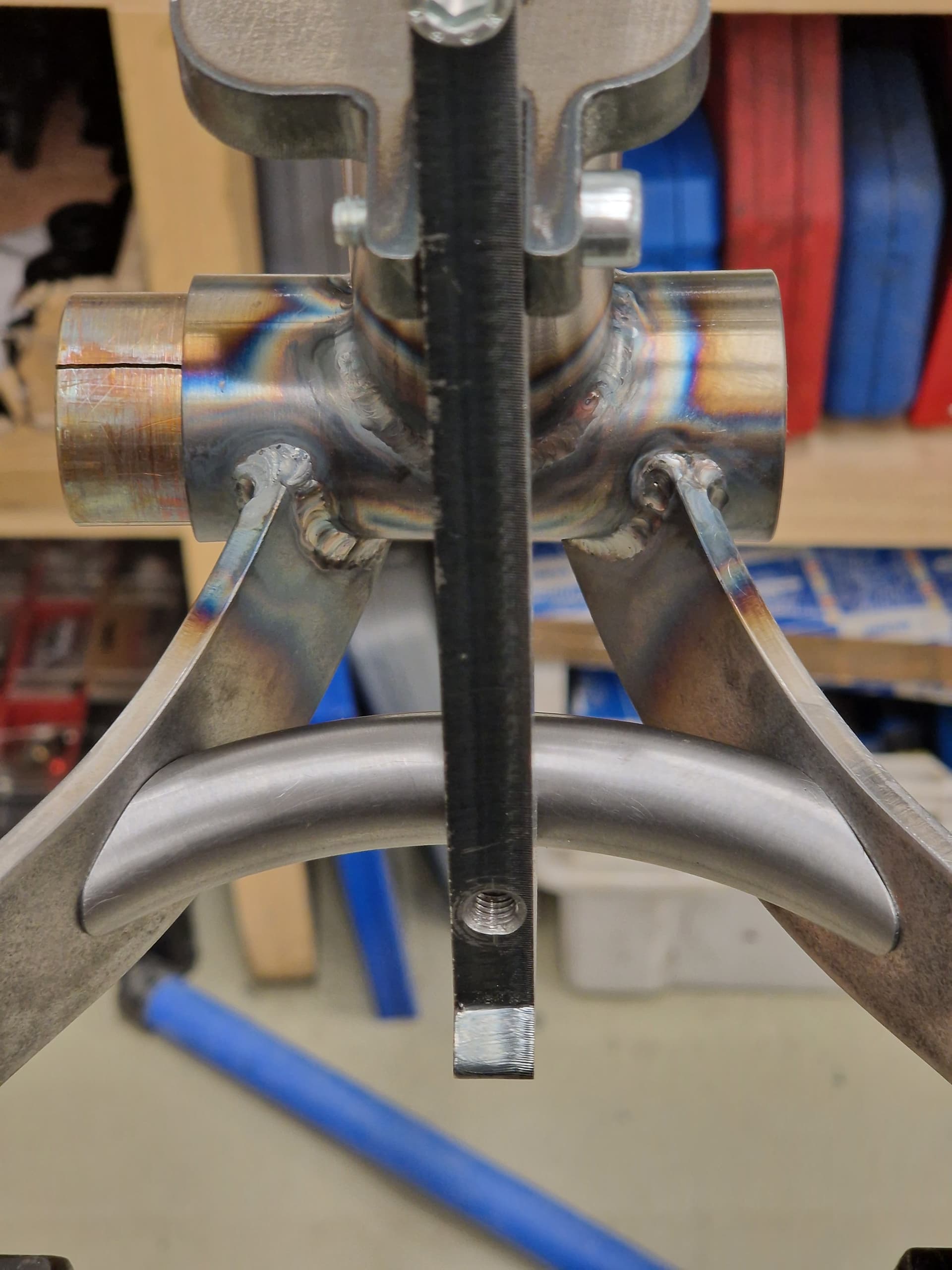
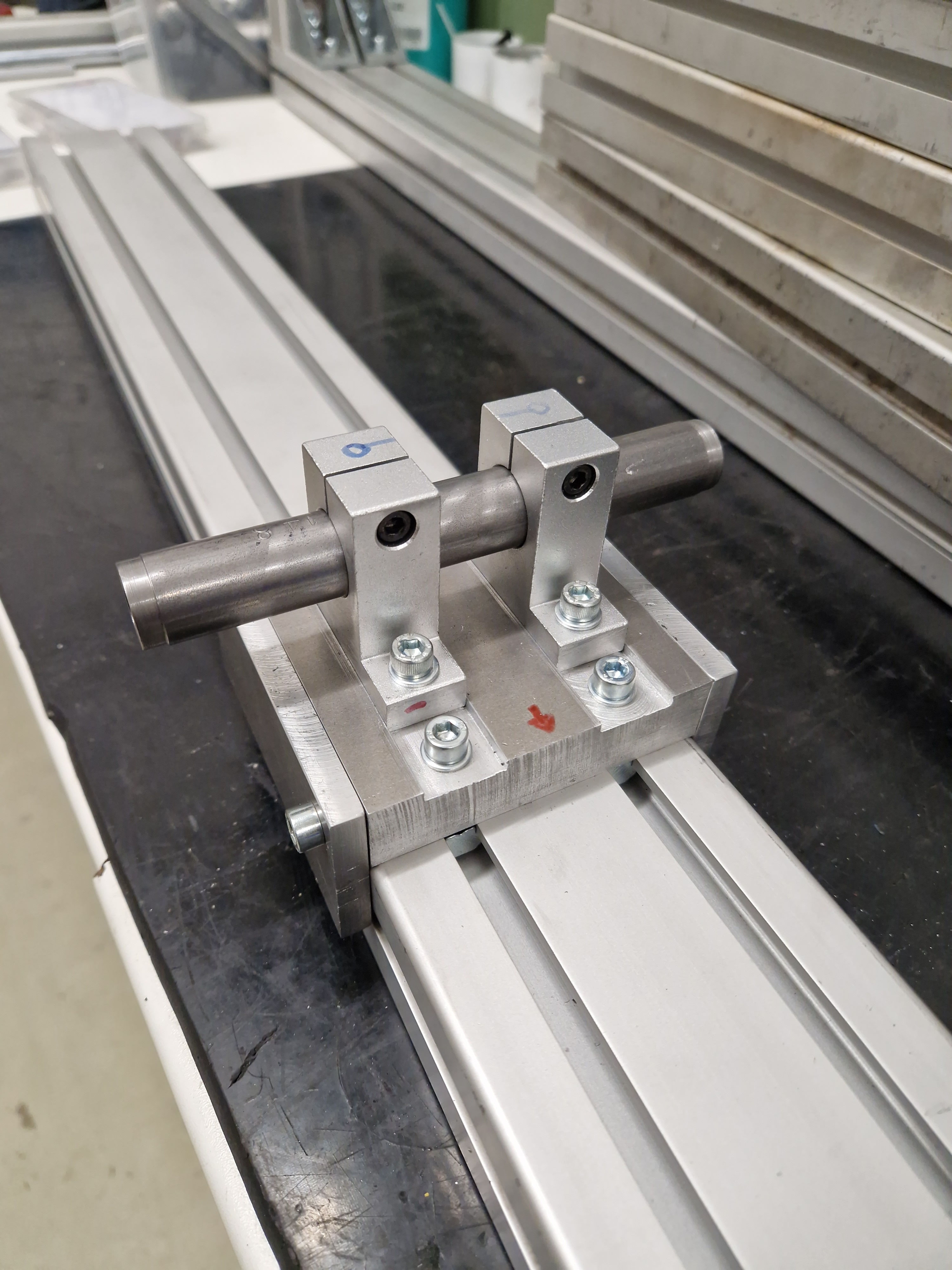
Fixture for locating pivot points.

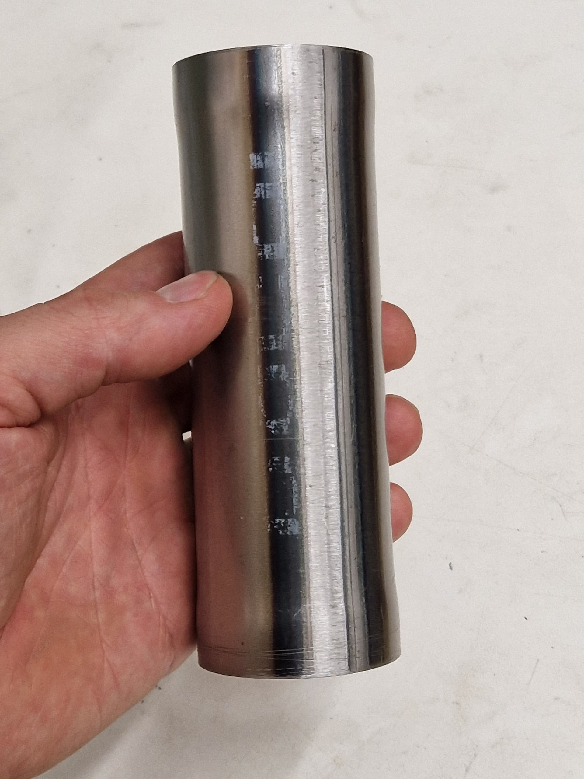
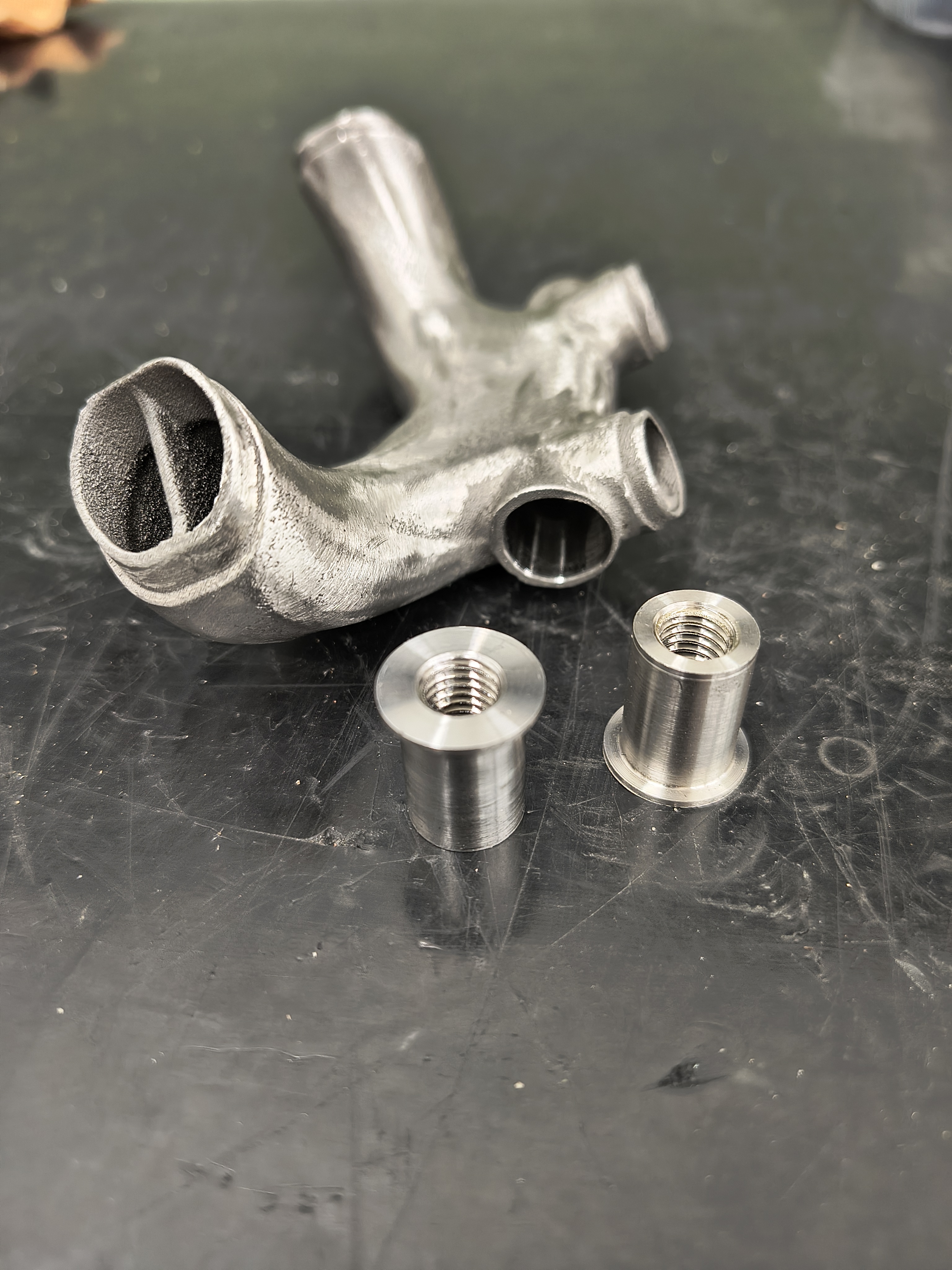
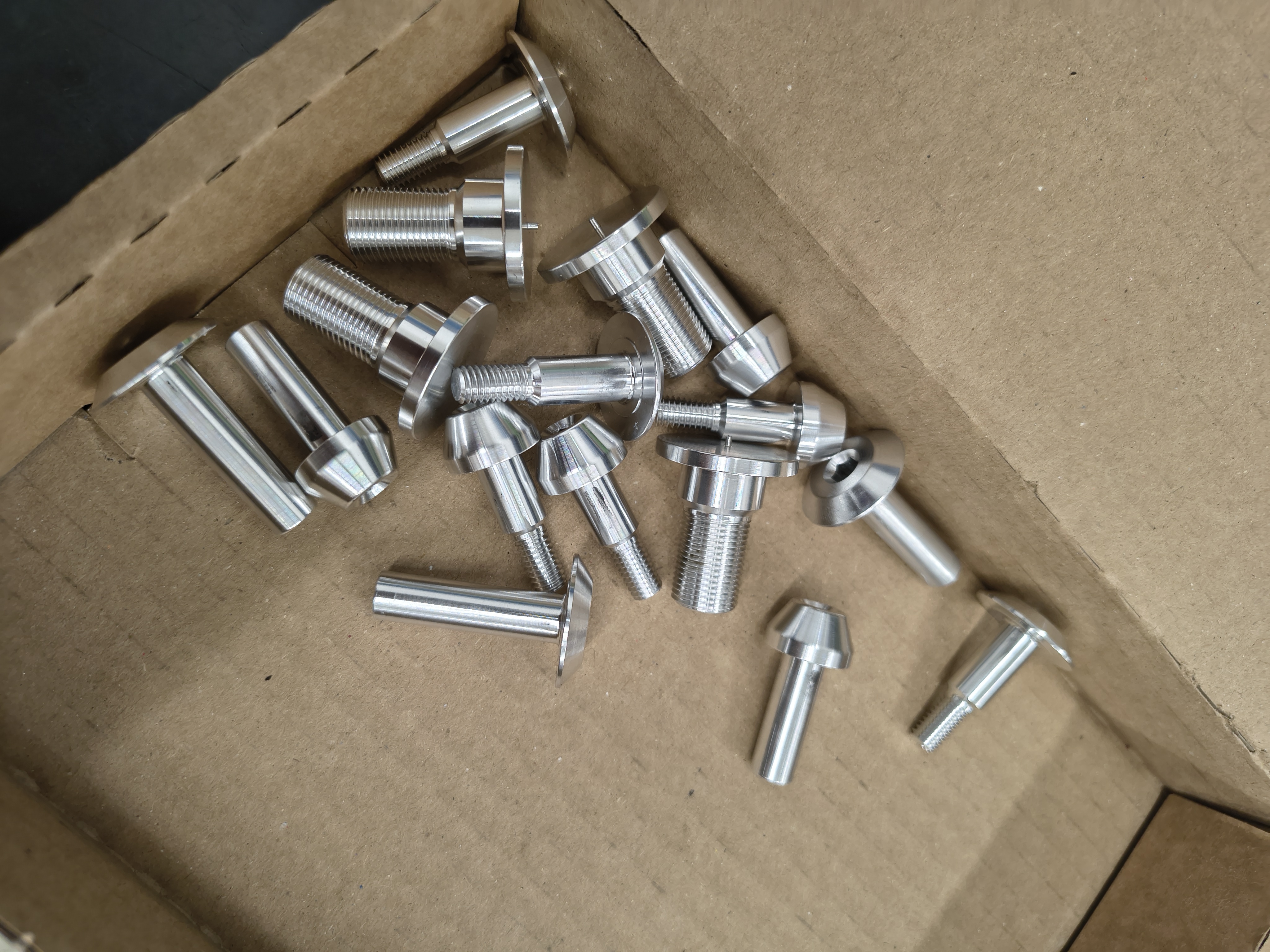
Turned these screws to locate the pivot points more precisely.


Almost ready to cut some tubes :smiley: :smiley: :smiley:


9 Likes

That’s amazing!

1 Like

400-500 MPa seems like a lot… How much do you trust your FEA, what kind of load and constraint assumptions did you use here?

Apart from that, super nice design work! I love the sheet metal pinion bridge!

1 Like

Thanks!

Well I have to trust, don’t I :laughing:

Actually, now that I think of it, I did change the seat tube from 35 x 1 to 34,92 x 1,24 at some point. So, the stress on the seat tube probably went down from that…

I’m on a different SW license now with a different laptop, and going through the archives is a bit of guess work at this point for me also :smiley:


For now I have aimed for the maximum stresses to be max. 400MPa, it has worked so far… But also, I’m 65kg, I ride rather “springy” through the feet, and let’s face it, Finland is not quite the Alps :rofl: So, for some people in another part of the world, this might have failed.

And also, I kind of wanted to leave some point which would fail to see if it fails where the FEA predicts…


In the simulation I have 6000N of vertical force on the BB. Rear axle is a fixed hinge.

Actually, while simulating the v3, I discovered I previously had the front axle supported the wrong way, and the headtube was not able to rotate freely (it was able move freely horizontally though). With the v3 simulations, there is definitely more stress on the HT/DT junction.
So yes, FEA is very easy to get wrong.
But still, I haven’t had any HT/DT fails, without gussets and with straight gauge tubing.

Haha, definitely! I usually look at the displacement first (with a scale factor) to see if the structure deforms the way I would expect it to. If it doesn’t, I try and find if there is an error in the constraining or if just my expectation was wrong. Usually it’s the constraining :wink:

A “rule-of-thumb” number from professional bike designers for impact/bottom-out would be to take the max spring force (let’s say 350lbs/in → 61N/mm) at full compression (60mm stroke length for example) and multiply by 2.5. In this case, that would be 9.15kN. It takes into account the “clonk” of hitting the bump stop in the shock… This would then be fed into the shock mount and rocker link of course.

The 6kN you are using on the BB is probably well on the safe side of that, depending on your motion ratio, so the 400MPa would be an absolute worst case scenario :wink:

Do you know if the SolidWorks simulation package allows you to inspect/influence the meshing?

1 Like

Well, I’m glad the bike industry has settled for a measly 2.5 safety factor instead of 3.14 :smiley:

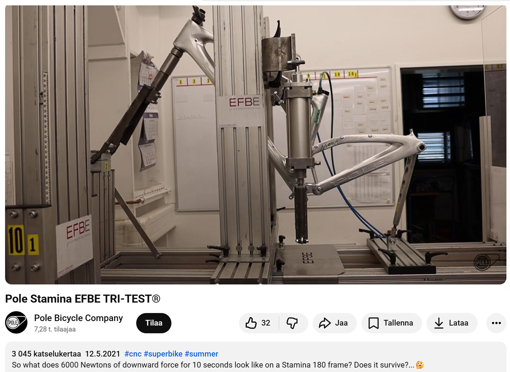
I did some calculations back when, and got a bit smaller number, but the EFBE-test is done with 6kN, so that is what I have used also.

But still, I don’t think the FEA at this point is about the absolute values, but rather smoothing out the high stress points.

We also know that a few 400MPa events does not do anything permanent to a tube that has yield strength of 690MPa (Docol R8). But some amount does result in a fatigue crack (which we see in aluminium bikes all the time :rofl: ).

A better solution would have been to leave the middle section “open” and weld only the sides. But then again, I did not want to leave a pocket which would rust… Maybe the good ol’ sheet metal style rocker mount is actually the best solution, for a steel bike at least.

So, the vertical shock does induce a lot of force and stress to the seat tube, no matter how the rocker mount is made. A horizontal shock would be a lot better because then the rocker / frame would not have to change the direction of the force from seatstay to shock.

And yes, the mesh is one big factor and of course it is adjustable in SW. For me, it is a battle between being precise enough for the mesh to actually mesh, and at the same not being too precise that brings the laptop to its knees and having to calculate for any more than a few minutes. I don’t have a picture taken, but I will take one the next time.

Thanks for the input!!!

2 Likes

That’s probably the smartest way to use FEA in our context anyways… :grin:

fatigue’s a b*tch…

2 Likes