I’m designing a 20mm delta adjustable dropout (e.g., 415mm and 435mm chainstay length) where the thru axle passes through a permanent hole integrated into the frame for maximum ruggedness. I’m designing a steel ATB to be built. 20mm delta is basically “Go big or go home.”
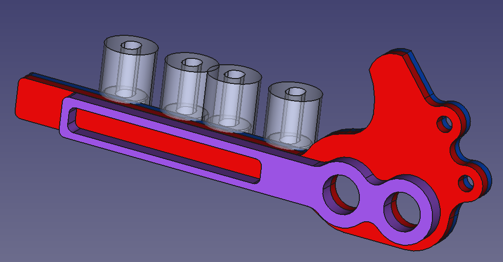
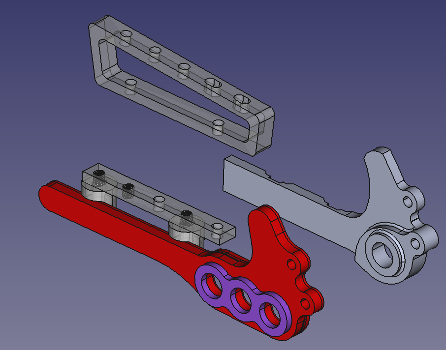
There are two sets of 34mm c-c flat mounts (brazed to the main body in this rendition), each set of two are offset from each other. When you shift the axle location you also shift the disk caliper location. The drive side is not shown since it is much simpler. It follows the UDH standard, but the inner most option (say 415mm) would not work with a “full UDH” derailleur because there is no clearance for it to swing.
Right now I’m playing with options. For $230 I can have this non-drive side dropout body CNC’ed from 4130, and would make it look prettier if so. For $90 I can have the purple, red, and blue segments laser cut from 4130 sheet metal, then brazed as one. Can the segments be brazed without comprising strength vs one CNC body in the hands of an experienced builder?
Here is 6.9K Views and 119 Likes worth of answers. When combined with a 10mm change in the fork rake affecting steering trail, I’d say allot in terms of road riding versus gravel, 32mm tires versus 57mm tires. The ability to change total wheel base say 30mm, trail, and CS length on the same bike would be fun for some.
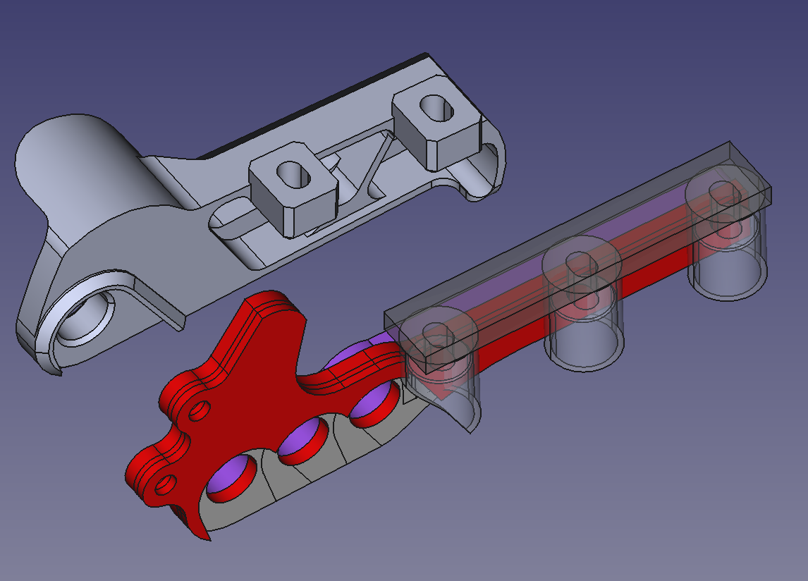
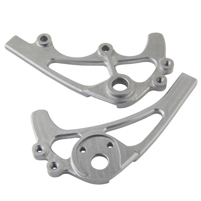
Lemmy asked if 20mm really matters. Here is the concept taken to a 34mm extreme with an option for 17mm as well. I’ve attached a Paragon dropout to emphasize my blocky rendition could look pretty. This version would use an adaptor shown to allow for the 17mm option.
Does anyone want a bike that morphs from a 440mm CS down to 403 for example? I’m more interested in a drop bar bike that morphs from 435mm CS gravel to 415mm CS road. Maybe 34mm is useful for swapping between 29er to 32er?
Brazing three slices together will not be as strong as if it were one piece of steel as steel is stronger than brass. But it will be perfectly strong enough. The metal at a dropout is very thick because you’re bolting things to it and don’t want it to bend or get crushed too easily. There is already way more metal there than in the stay just in front of it. You don’t even need to use 4130. Just regular mild steel would be more than strong enough.
Innovative design! On my fixed gear with track dropouts the wheel can probably move by 20mm just taking up chain tension. I’ve never noticed a difference in how the bike feels. But I always ride sitting down, where it is probably less noticeable.
Idk why you’re confused, I’m literally using your own language
Correct me if I’m wrong but this forum is generally for folks making things that are measured in fractions of a mm, 20mm in any direction is going to change your bike and riding experience quite a bit…..
You didn’t “touch a nerve”. I’m making it clear that negativity for the sake of……nothing…..isn’t cool and if you feel that an idea doesn’t have merit maybe tell us WHY you feel that way insted of simply saying it’s a nothingburger and contributing nothing else to the conversation.
I think having the options to change geo and associated ride characteristics is a great idea for gravel. Its been going on for a while in the mountain bike world. I have paragon rocker on my HT to switch between 27.5 and 29 rear wheels.
One thing you could consider is something like the double decker from Cotic? Effectively you play with multiple elements of geo and how it rides. RAAW have an axle similar to your design, but with interchangeable ‘chips’ to move the axle position and associated brake mount (RAAW Rear Wheel Axle Kit - Complete – RAAW Mountain Bikes).
One thing to note though, outside the geek cycles, most people seem to just leave adjustments where they came
This holds very true. It’s rare that customers change the adjustments. However, it is useful from a manufacturing standpoint if you want one bike to appeal to more than one type of customer. Done right, it can reduce SKUs, and potentially increase the potential buying pool. The key here is that you have to be making enough of that product to justify the marketing spend to explain the differences sufficiently for the customer to understand that’s what they want, or to get it in front of the eyeballs of those two different potential buyers.
It’s an interesting concept.
The 29" to 32" swap aspect is valid - the difference in diameter between is approx. 70mm (rounded up) - Ø814mm for a 32" Maxxis Aspen, and Ø747mm for a 29 x 2.4" Vittoria Syerra. So that means a 34mm change would work well from that perspective.
But you may also want to consider the BB height/drop as well when swapping wheel sizes.
Instead of having 3 or 4 separate FM lugs, maybe you could make the dropout as a 2-part design where you have a movable flat mount piece. Should help take some bulk out of the design.
I’ll just leave this here for you.
Literally the first definition when looking up the word “piddling”.
Accuracy matters. And so do manners.
No sexism there? We all just need to wear more panties irrespective of gender?
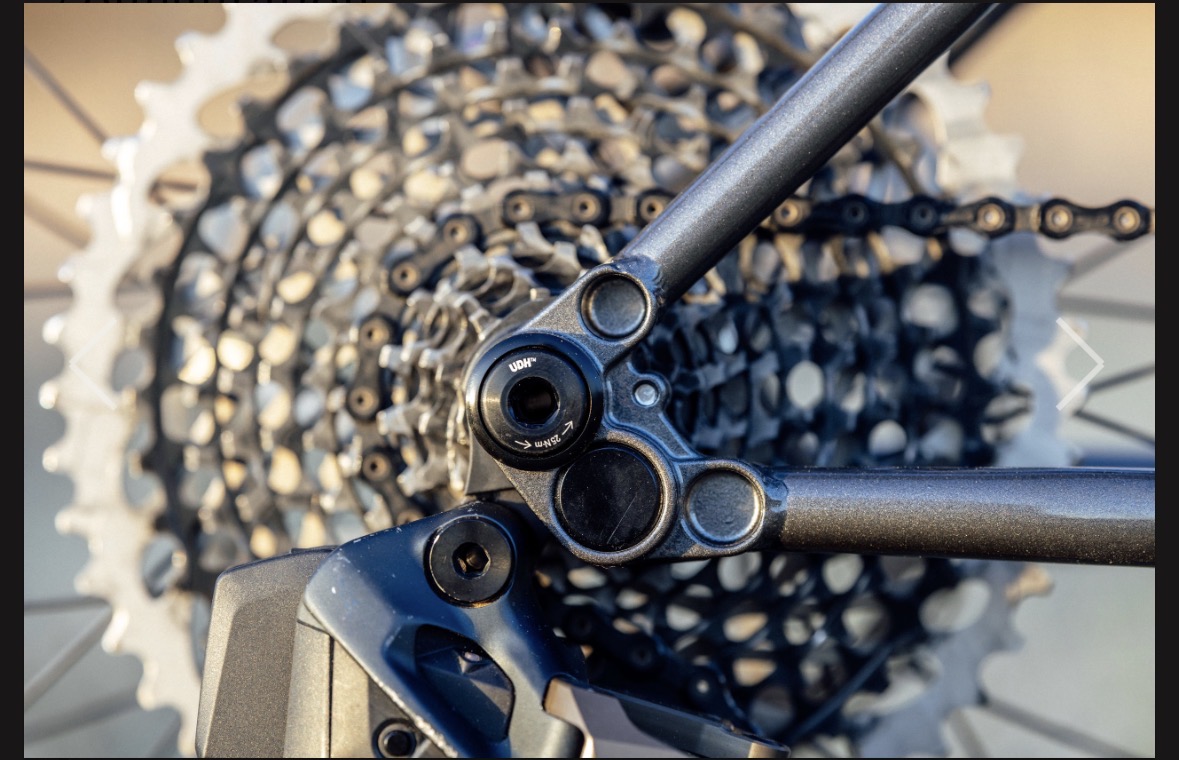
But to to point about on design and customer usage. My brother-in-law was showing off his new fancy TREK gravel bike. And i was like ‘hey, that’s cool! It have an adjustable dropout and brake mount’. His response was ‘ wants that for? Never noticed it’
Yup! The audience appears to be just geeks, so far anyway. I really like JMY’s argument for the ‘go big’ option of 34mm delta, and to me makes sense to also have a 17mm in-between. Working on his suggestion for moveable flat mounts, and I’m playing with two fixed FMs and let the adaptor do all the work. So far it works for a 160mm rotor, but making it also work for a 180mm rotor has me stumped at the moment. There is just not enough real estate to accommodate what would be six caliper locations (3 for 160, and 3 for 180).
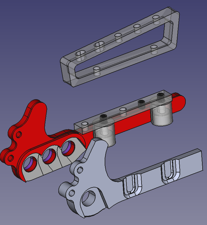
Based on feedback from from Guy153 I’m still showing a design using laser cut sheet metal brazed together. Based on feedback from JMY the max delta is 34mm, with 17mm also. Based on other posts in this forum I focused on 160mm and 180mm rotors. The dropout body (w/o the braze-on flat mounts) is 154g, vs a Paragon offering at 115g for comparison.
The 160mm adaptor’s threaded and non-threaded holes are deliberate. Via shifting the adaptor 17mm the caliper is shifted 17mm. Via then rotating the adaptor 180 degrees the caliper can be shifted to the final 34mm. The hex screws’ position and direction is like a puzzle, but I think I got it correct.
I needed the 180 adaptor to have height to allow room for the hex bolts to be threaded into the caliper. Two of the upper holes are slotted to help wiggle the hex bolts into place, but at least one caliper bolt is always in a non-slotted hole.
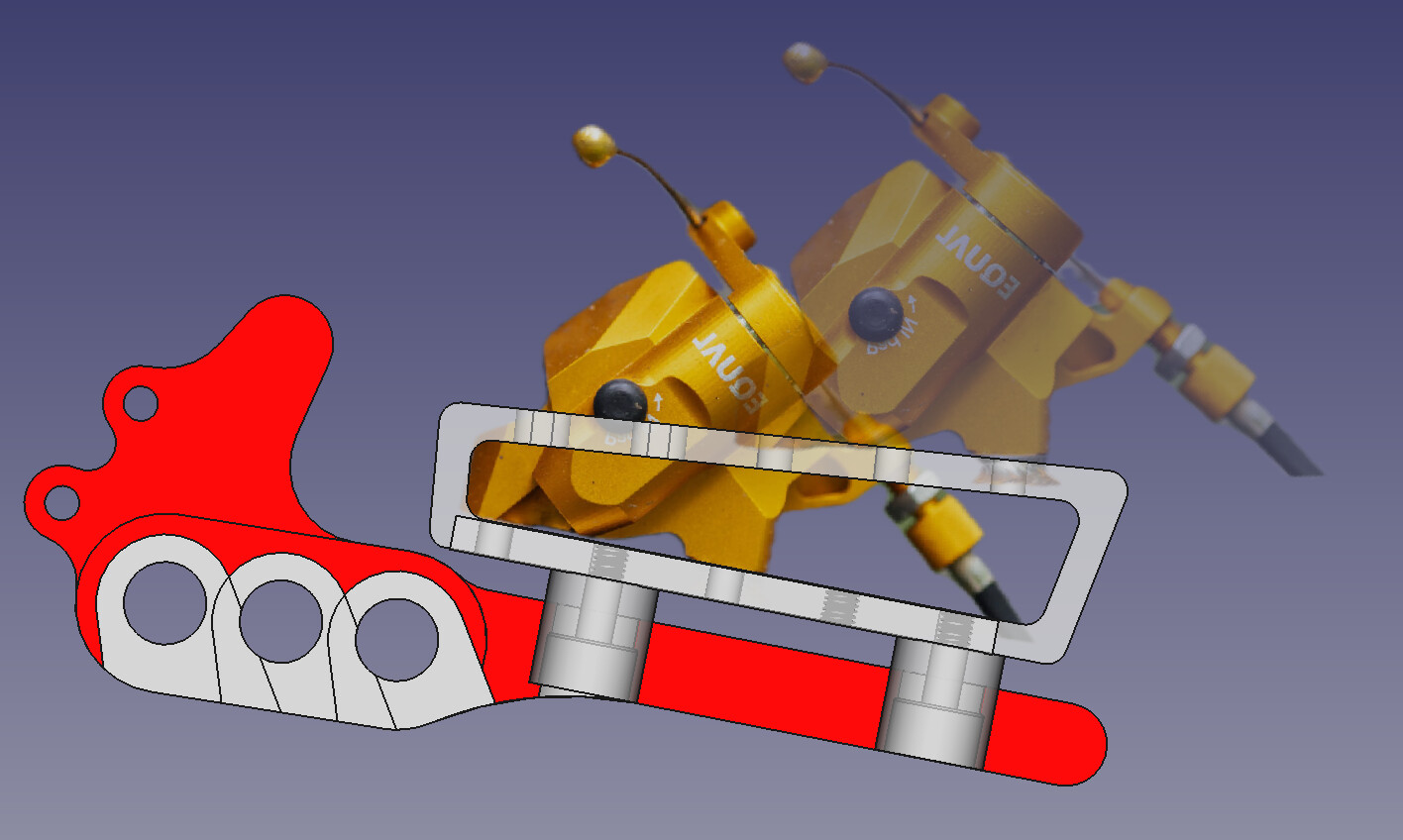
The bottom image demonstrates a rotor at the longest effective CS for a 160mm rotor, and the shortest effective CS for a 180mm rotor. Not at once…just showing spatially the two extremes that the rotor translates. The math says the derailleur would need an extra 6 links of capacity to accommodate the two extremes (34X2 / 25.4 X 2 [links per inch] rounded up to 6).
This meets my goal of the rear axle passing through an actual 12mm hole integrated into the frame for robustness, vs a flip chip or sliding dropouts. I otherwise cast no doubt on those designs. I really do now like the “go big” option of 34mm, and now think of 17mm as more fine tuning road/gravel, which was and remains my motivation. It’s sort of the dropper post of CSs, if you know what I mean.
Awesome work on developing this! the 34 mm triple option is most appealing to me
I’ve been looking for something exactly like this. I remember the Evil Imperial which was built with three vertical quick release drop outs.
I was actually interested in the prototype potential. But I could totally see selling bikes with this fitted. The Paragon adjustable only provides 15mm I believe.
I don’t like adjustable drops anyway cause as a mechanic I’ve seen too many come loose or be misaligned
I’m currently using the Paragon low mount with rack eyelets