My main supplier of head tubes had a shipment go walkabout leaving me slightly fuqed.
I’ve only been 3D printing parts for a short time but I’m already hooked. The freedom and accessibility just makes so much sense to me and the way I like to work.
I’ve considered printing head tubes but so far avoided it as I try to stick to the ‘must solve an actual problem’ rule.
I hate keeping stock of things, putting down relatively large sums on MoQs, etc doesn’t really gel with the way my business works. And it can restrict what is feasible. Printing specific parts for each frame order that comes in means almost anything is possible and that’s what I’ve always felt is the trump card of the frame builder - custom shit.
Tl:dr I really like 3D printing.
So who’s printing head tubes. What have you learned? Anything to avoid, etc, etc?
I know of a few larger brands who are already doing this but I’m interested in your experiences.
I had to google that as I’m fully immersed in mtb land. I would imagine that’d be pretty easy to model and print and also add your own flair - all things printing is great for, creating weird shapes etc.
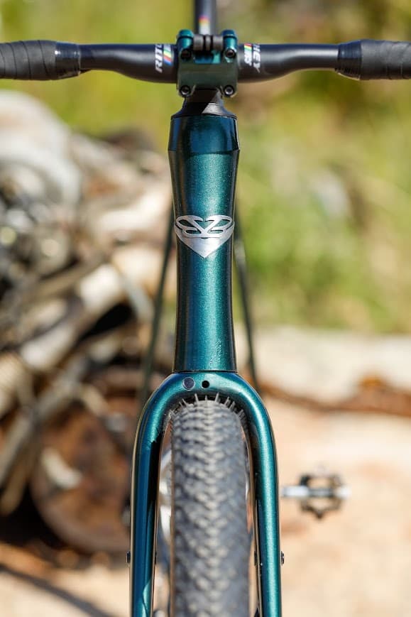
FWIW I would be printing a 44/56 tapered headtube with stepped tube interfaces. Perhaps with hose/ cable ports situated to reduce cable rub.
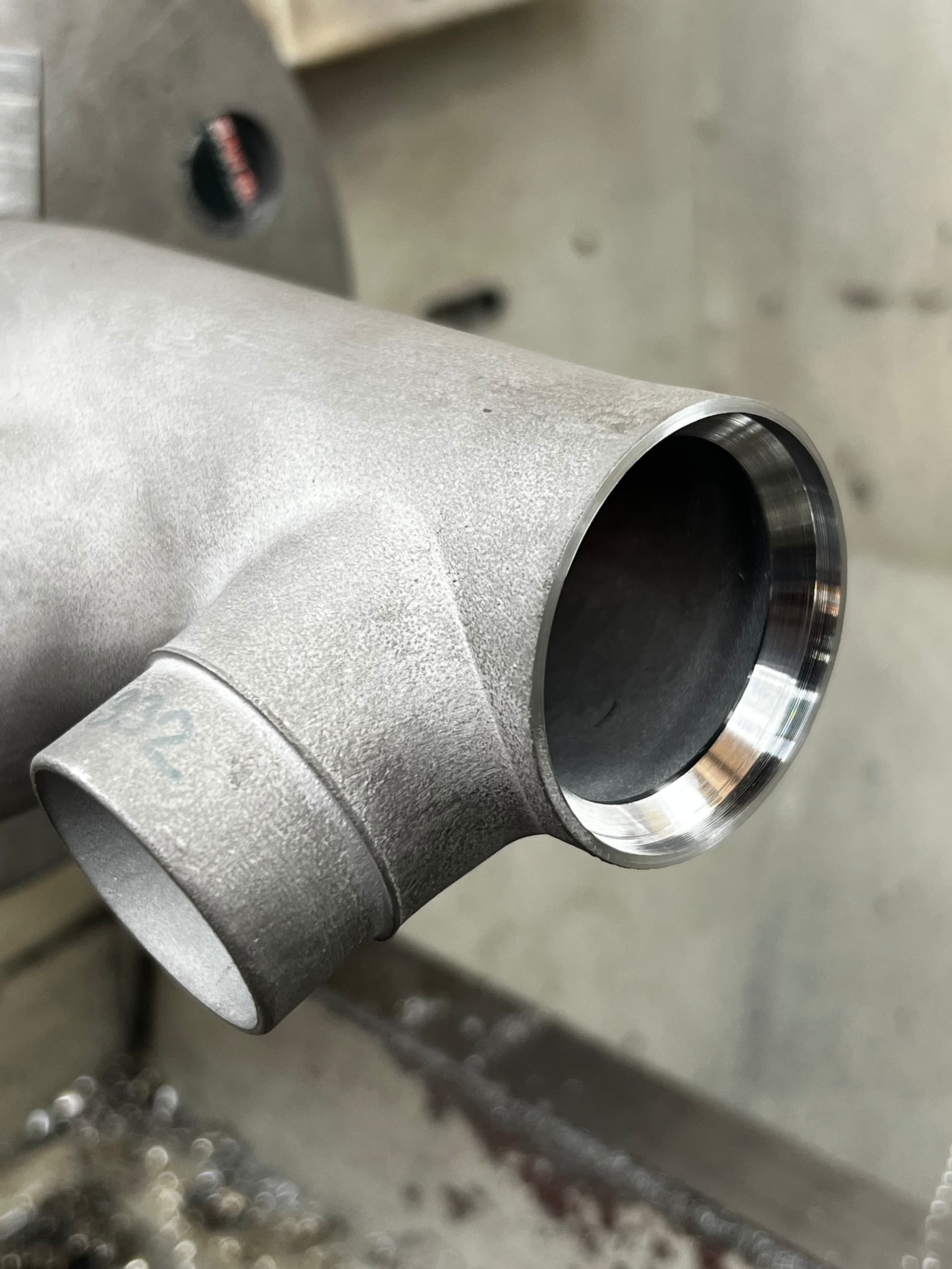
I print my head tubes- I’m using IS52/IS52 configuration. I print them 0.5mm undersized and ream them to size. Reaming the taper at the bottom is a real bear with hand tools(the pressure you need to actually remove material is way higher than the spring tension provides), so I’m planning on making an arbor for my hand reamer to chuck it in the mill.
I love the ability to print my logo into the head tube as well as create fun geometry, and I get a way to move the welding away from the bearing surfaces and only have to cut my tubes flat.
All my prints are heat treated 17-4PH. It ain’t cheap. I just looked and with heat treat, duties, shipping etc it was a $200 part on it’s own. Worth it? depends on how much you like swoopiness! I think it’s worth it for me.
One thing I ran into on the last one- make sure you do a thickness analysis before you pull the trigger. I had neglected to consider that after reaming the part to size including deepening the race, I was getting scary thin where the scalloped design on the outside runs into the straight wall on the inside. I decided to scrap the part and redo it because of the risk- ack!
I got a price on a 110mm long 44/56 tapered head tube in 17-4. Super simple, just the head tube section, no DT or TT fitments. 2mm wall throughout (anyone got notes on the wall thickness?)
~100usd
Not cheap. A quote from last year from a Taiwanese vendor came in at 750usd for 100x head tubes in mixed sizes up to 150mm or $7.50 per part of course. I pay double for the same parts via a supplier currently but there’s still a gulf between them - 85usd.
I can save 40 on tubing because I’d no longer be forced to use the only tubes available in longer lengths (because printing in the TT/ DT connection fitments would shorten the C-C).
I don’t think I’d save any time on mitring, at this point putting a mitre in takes no longer than putting in a nice clean perpendicular cut with a chamfer for welding. It could help avoid brain farts when pulling numbers from the computer for each custom frame, I score zen (not meaningless).
I don’t think I’d save any meaningful weld time either. I would avoid tricky, annoying joints - more zen.
So I’m looking at ~45 increase in materials in return for decreased admin (consolidating suppliers), increased chill, further customisations (cable ports, head badge/ logo) and its pay as you go, I can change anything at any point and not be tied to 100x stock sitting in my workshop.
Just speaking for myself who is a full-on hobbyist who doesn’t have to think about lawsuits or building for worst-worst cases, IMO 2mm is overly aggressive through the whole part. If it’s a drop bar bike, we’re subjecting the head tube to the same forces an EC34 headtube can handle no problem while increasing the diameter significantly. I use localized thick areas at the bearing races so there’s no issues there and can get nice generous fillets internally, but I thin mine down to ~1.4mm through the majority of the body. I also always spec heat treat because for the slight increase in price the peace of mind is worth it to me that i’m working with the strongest possible configuration. Additionally since I build the TT/DT transitions into the part I have huge radii/surface blends that should significantly help with joint stress at the HT compared to simple fillet weld to a tube.
Please don’t sue me if this doesn’t work for you .
Agree with your take and similar approach to Dustin. I’m down to 1.2mm wall will localised thickening and I machine the bearing seats on the lathe. The last head tube had everything in it for a 510 reach frame, 140mm long. US$160 heat treated 17-4. On this one I printed a plate to hold it in the lather but that was a pain to remove in the end. Going back to an internal arbor style setup.
Yes, all parts in 17-4. It is freakin shite for drilling and tapping with HSS and even cobalt drill bits but ok with the carbide tips in the lathe. If I got some drill bits specifically for hard materials and Guering spiral taps it would be much better. The top is for IS42 with a 46 OD bottom IS52 with 56OD
I’m in two minds about printing the tube interfaces. Are you silver brazing yours? I think that could be a good way to do it. I’m wary about doing a welded lap joint on a part of the frame that has a ~1000mm lever on it. Seems to me that forces will all come back to that joint and maybe fatigue will kill it quicker than a mitred joint with more surface area. Less of an issue on road bikes of course.
I may just print the head tube itself with some nice cable ports and an integrated logo/ badge.
Another potential win would be the possibility to target a specific stack number and not be tied down by 10mm increments in HT length.
Bike novice but metal printing (LPBF aka DMLS/SLM/DMLM) expert here.
Thickness:
I wouldn’t print anything under 1.2mm thickness if structural. You can machine it down thinner- but I would print minimum of 1.2mm to ensure consistent mechanical properties.This is a rule of thumb with LPBF. Below 1.2mm net-shape things start to get brittle in most setups/alloys.
Alloy:
Alot of bike folks are printing 17-4 and I advise AGAINST this. 17-4 is a complex alloy when it comes to heat treatment and heat-affected zones. You can end up with some weak and brittle stuff depending on its thermal history. This is dangerous to weld without a post-heat treatment AFTER welding. I realize a bunch of reputable bike makers have been using 17-4 without known issues, I still think its a bad idea.
I recommend staying away from 17-4 and using 316L instead. 316L is weaker but far more predictable. ‘Bad’ 316L is safer than ‘bad’ 17-4. Also note that LPBF 316 is often STRONGER than ‘traditional’ 316, so you can more or less expect >450MPa, even though traditional datasheets may list something like 200MPa
If you want max strength… get alloy 718. 718 is weldable to steel using the correct settings. It may seem odd to move to a ‘super-alloy’ like 718, but its common in the LPBF world. 718 in its ‘worst case’ condition will still have >550MPa yield strength combined with very high ductility. Don’t bother age hardening the 718. Same problem as 17-4 here- you really need to do a final HT AFTER welding. However, 718 is still pretty badass even in its worst-case condition, unlike 17-4, which might be garbage.
headtubes:
I am not an expert here, but my current hobby project uses a printed headtube made of AlSi10Mg bonded to carbon tubing. I went with a 44mm ID to use an IS44/EC44 setup. I left ~0.5mm stock on the diameters to ream and its worked out well so far… I went with something like a 4mm thickness at the max stress spots, and tapered to ~1.4mm in low stress areas. This is aluminum though, a weak one at that.
Venders and cost:
I do my own printing. I work for an industrialized supplier.
If I were ‘independent’ I’d probably use Cloudcraft to do quotes. That means it’ll probably come from china, and the quality makes me nervous. However, I am beginning to suspect this is just my own bias for ‘domestic’ manufacturing. I’d build a bit more margin into the design and maybe also have them produce some test coupons.
So far all my prints have been in 316 but I was looking at 17-4 as a stronger alternative for a critical area of the frame. Perhaps it would be best to stick with 316 and not be shy with the wall thickness. I’m using 316 at ~2mm elsewhere (that’s where my 2mm wall further up the thread came from).
Either way this part won’t make it anywhere near customers frames until it’s been properly tested. This is more of a hobby part for my own personal frames right now and a way to explore more printed parts.
@hank if I could pick your brains a little further while you’re here? There has been some discussion about whether heat treating 316L printed parts is worth while/ sensible to increase strength - since the material can’t be ‘hardened’. Would you say it’s always a good idea to heat treat printed parts regardless?
I live and breath LPBF and am a bike geek. I’ll help however I can.
Even though 316 isn’t a ‘age hardening’ it is helpful to do a stress relief heat treatment on LPBF 316.
Reasons you want to run a stress relief cycle on printed 316:
it will make mechanical properties more consistent and increase ductility
it will increase fatigue life
it will decrease part distortion, especially if its done before the parts are removed from the print platform. Any good printing service should be doing a stress relief on 316 before platform removal.
Downsides:
cost
small decrease in ultimate tensile strength. The highest tensile strength will be ‘as-printed’. before any heat treatment.
A few years back I did some digging to try and find a balance of strength and fatigue life in 316. I settled in a stress relief cycle as follows:
heat to 650C in air, argon or vacuum, hold 2 hours, rapid cool in air or faster.
This is lower temp than many recommendations you’ll find. It has worked for me. It retains a bit more strength than if you use a high temp, but seems to be enough to remove all ‘residual stress’ you get in the printing process.
Appreciate you supplying the info about the materials. Definitely good to get some experienced advice. If I was silver brazing the 17-4 do you see similar issues to welding? If not, is there a way of NDT to the parts to be be able to ascertain if there were some ‘bad’ sections? I did go to 17-4 purely for that stated strength and have used 1mm wall at in the BB area with no failures so far. Not to say I am not right on the edge of failure there though.
Thom,
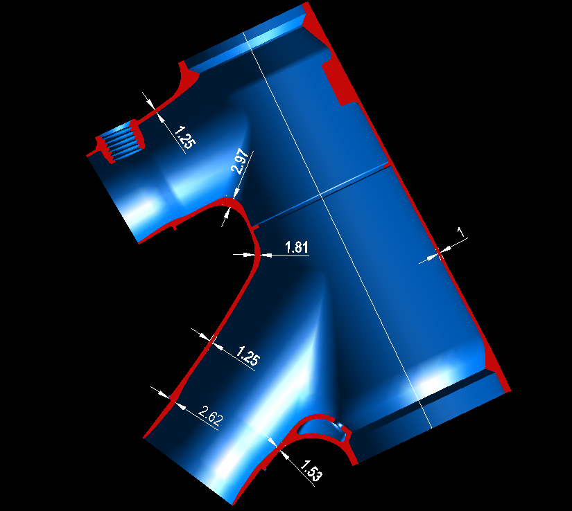
I went back through my models an marked up where I varied wall thickness and shape. Some would argue to not give away my ‘secrets’ but there are no secrets here and the benefit to the broader group having a better understanding of this is worth it. We don’t need failures and people being hurt. There are plenty of refinements to be had but I feel I am in a good spot with it.
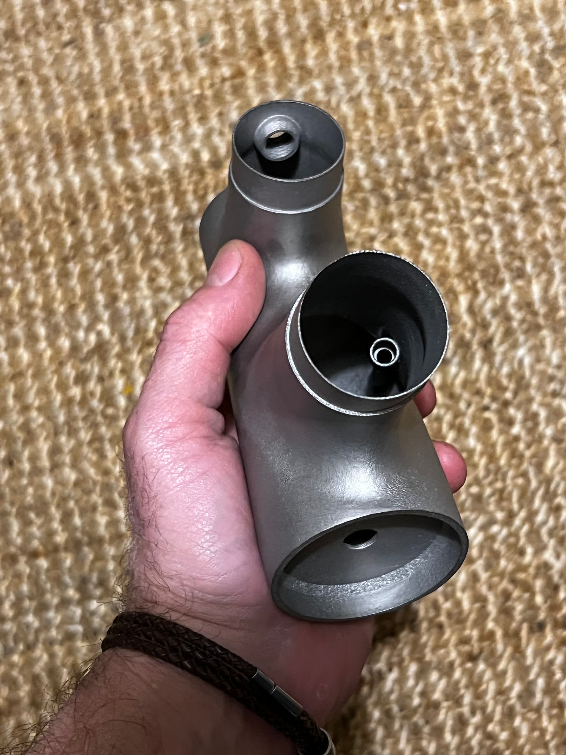
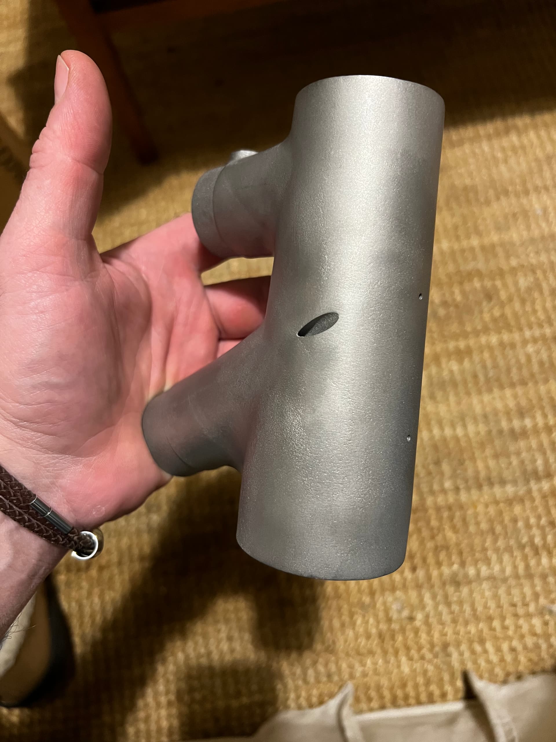
This is the latest head tube for a 510 reach frame. It has the internal shoulder for work holding in the lathe as well as a stiffenrr of limited effect. It also has a boss for the integrated Pademelon steering damper and a rotation stop at 90 deg to protect the damper.
I did notice the slightly thinner section at the bottom of the DT between the radius and the socket, 1.53mm, and will be removing that in the next print.
Delvin CC and TBD, I need to eat my words a little bit. I think there are circumstances where you can safely weld/braze17-4 and then NOT do a post weld-HT, but it comes with caveats.
I did some reading and refreshing
Welding heat treated 17-4 (H900, H1150, ect) likely WILL reduce the properties in the areas that got hot. Both strength and ductility will go down, but it’ll probably still retain quite a bit of strength and be significantly stronger than 316. The ductility is the scary bit. You may end up with something like 5% ‘elongation at break’ in the heat zone, whereas 316 will be super high, well over 30% worst case. I think the properties of ‘heat affected’ 17-4 will be similar to ‘condition A’ 17-4 (annealed). That’s a bit of a guess and I haven’t data that prove this completely.
So if you want MAX STRENGTH 17-4 will be superior, but it’ll be less forgiving at the extreme cases and it’ll crack instead of bending/denting.
718 is the best of all worlds, but it may be tricky to weld compared to the stainless alloys (is absolutely possible though). Perhaps brazed 718 is the magic ticket?
About brazing vs welding and which will have more problems from ‘heat affected zone’. I dont really know. Not my area of expertise. Whichever one has a lower temp, and less time at that temp, will be ‘better’ at reducing these issues.
Sean, of all the joining methods I would imagine that silver brazing has the least effect on 17-4 mechanical properties. In other studies it’s been found to have had only very minor impact. But those were concerning joining of 4130. My own opinion/ guess is that at silver brazing temps it’s unlikely to change much.