Rear suspension bearing arrangements, sizes and other info

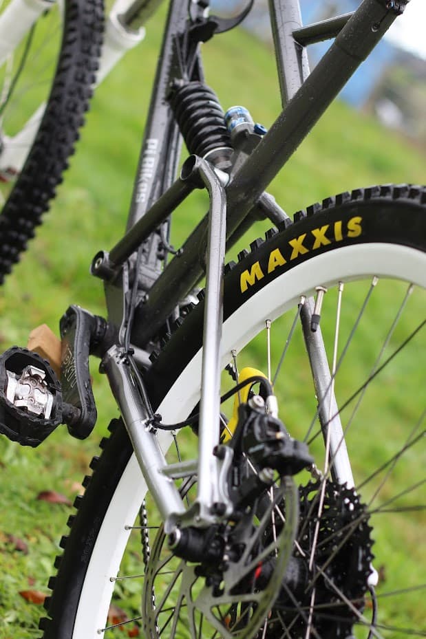
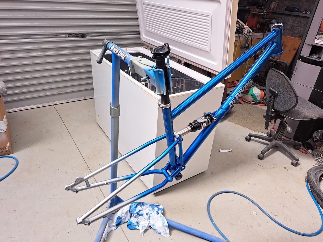
I have made a couple of single pivot bikes and have plans for some slightly more complicated bikes in the not distant future. It took me a long while to decide on how to lay out my bearings and preload them etc. I don’t know if the way I have done it is the best, or even good. But I have had zero issues so far with either bike so I figured I would open a discussion on how I have done it and maybe others could share how they do it and build up a bit more knowledge.

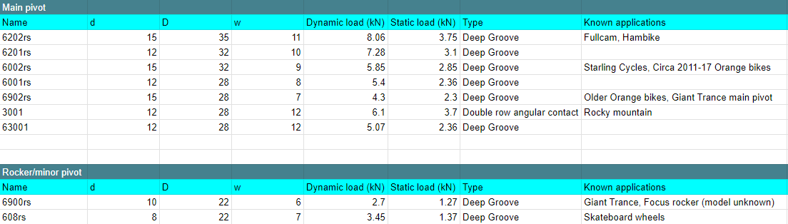
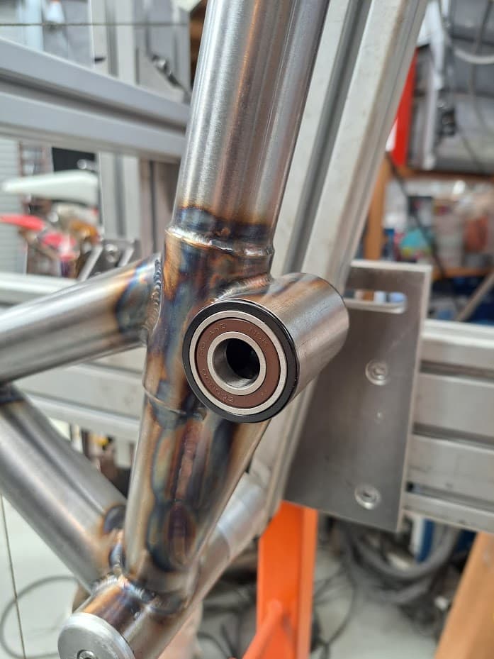
I started off by picking a bearing size, this took a while to decide on but I settled on 6202 because I wanted to use a 38mm tube for my bearing housing and at 35mm that would leave me with 1.5mm of wall thickness. Since then I have done a bit of hunting around a noted down some common bearing sizes that other manufacturers use and their load ratings and made a spreadsheet

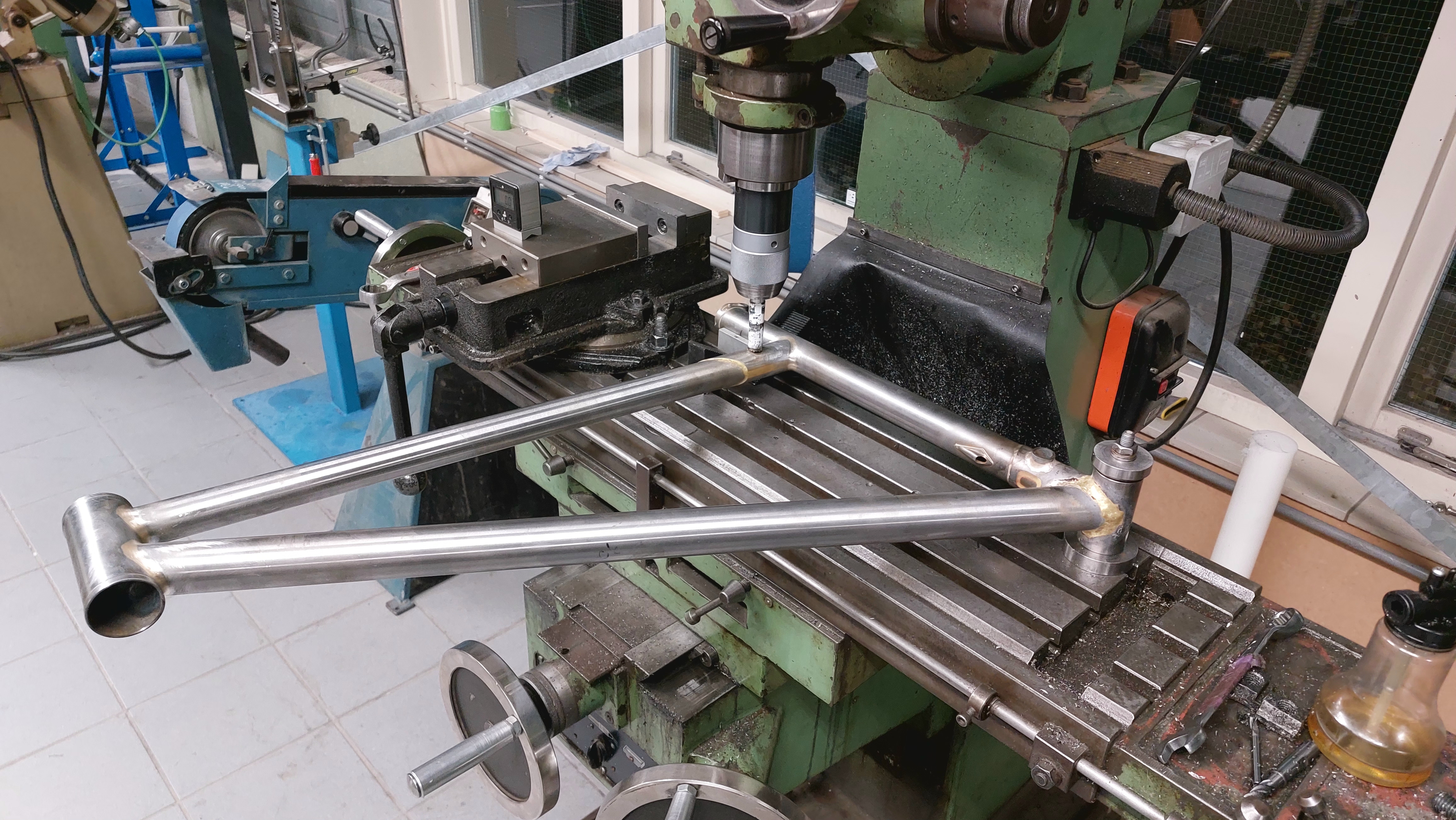
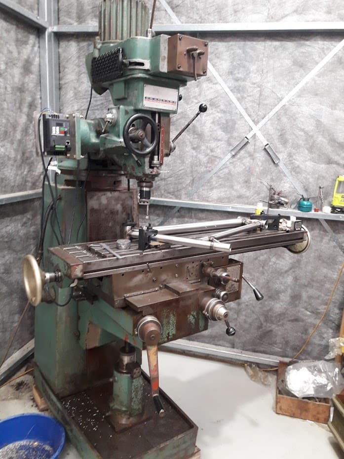
For my existing 2 full sus bikes I used the mill to bore out the bearing pockets with a boring head. This isn’t ideal, because I am not terribly talented at machining things and usually end up with some chatter going on. Its a pretty stressful operation with some pretty tight tolerances for an amateur.

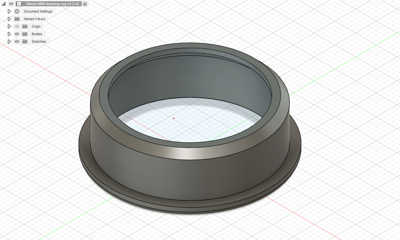
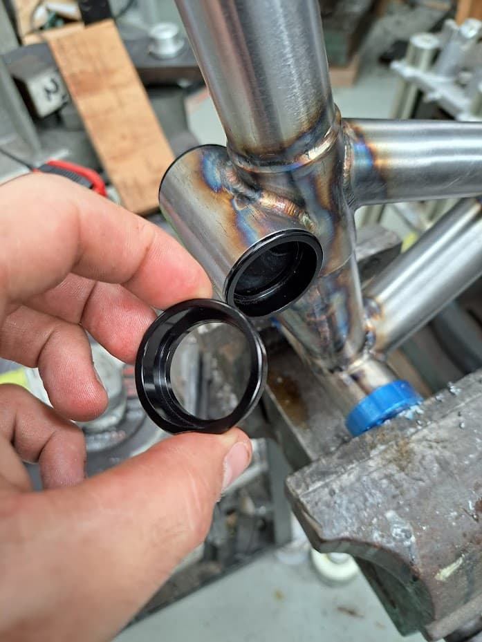
I got them both done ok, bike 1 is a little bit loose and bike 2 is a little bit tight but its fine. I am currently working on full squish #3 and decided that I needed to find a better way. So I drew up a 34mm press fit cup much like a headset that takes a 32mm (6002rs) bearing and got 20 cups machined in china from an Aliexpress cnc shop. Turnaround was 3 weeks and it cost me $150usd including postage so that was pretty sweet and I am sorted for the next 10 bikes. If anyone wants the model send me a PM.

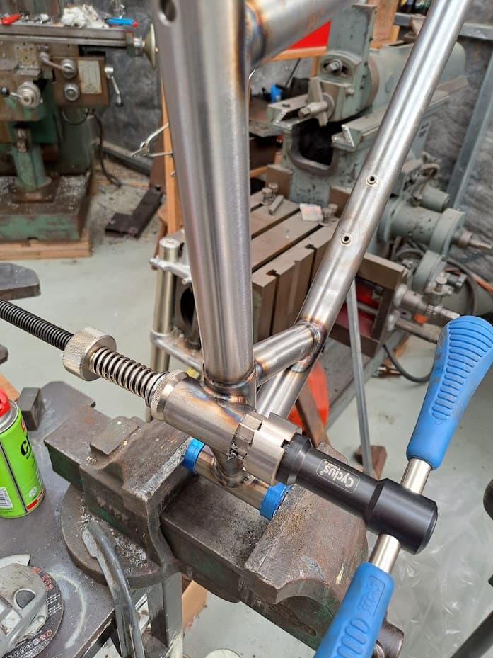
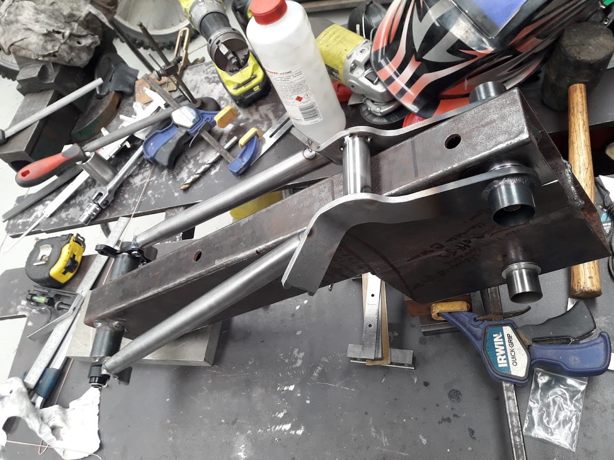
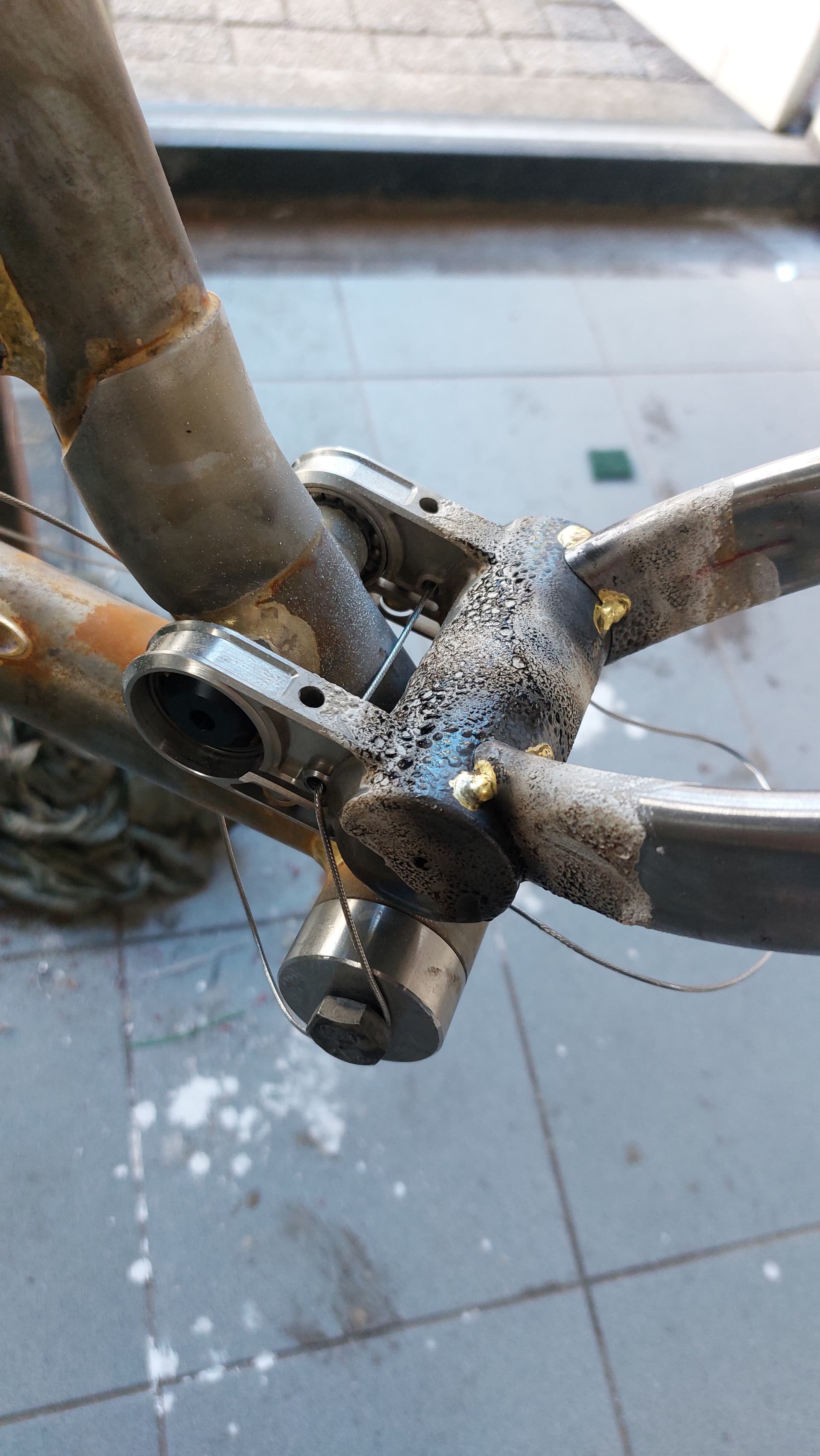
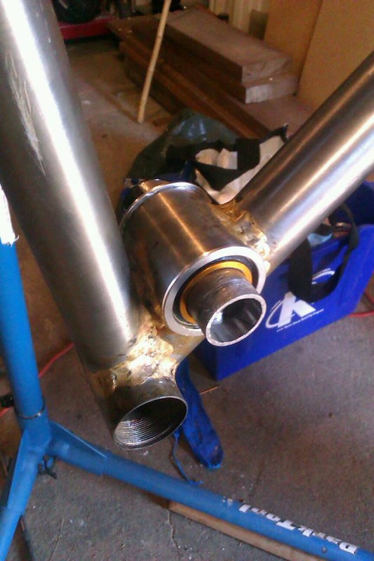
For preload I made the swingarm parts interface with the inner race of the bearings and made a shaft that went all the way through the swingarm and the bearing housing. I put M8 internal threads on either end of the shaft and faced it in the lathe so that when fully tightened it preloads the bearings by a set ammount. I have not been able to find good info on how to correctly chose a preload/tension ammount in a more scientific way than just doing it by feel so if anyone has any info on that the please share!


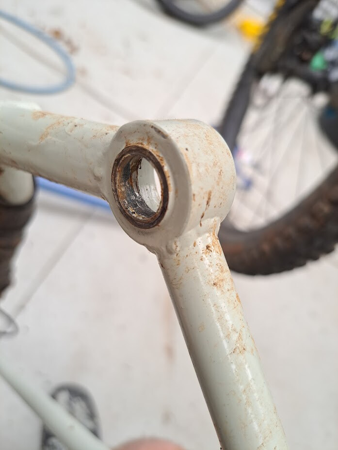
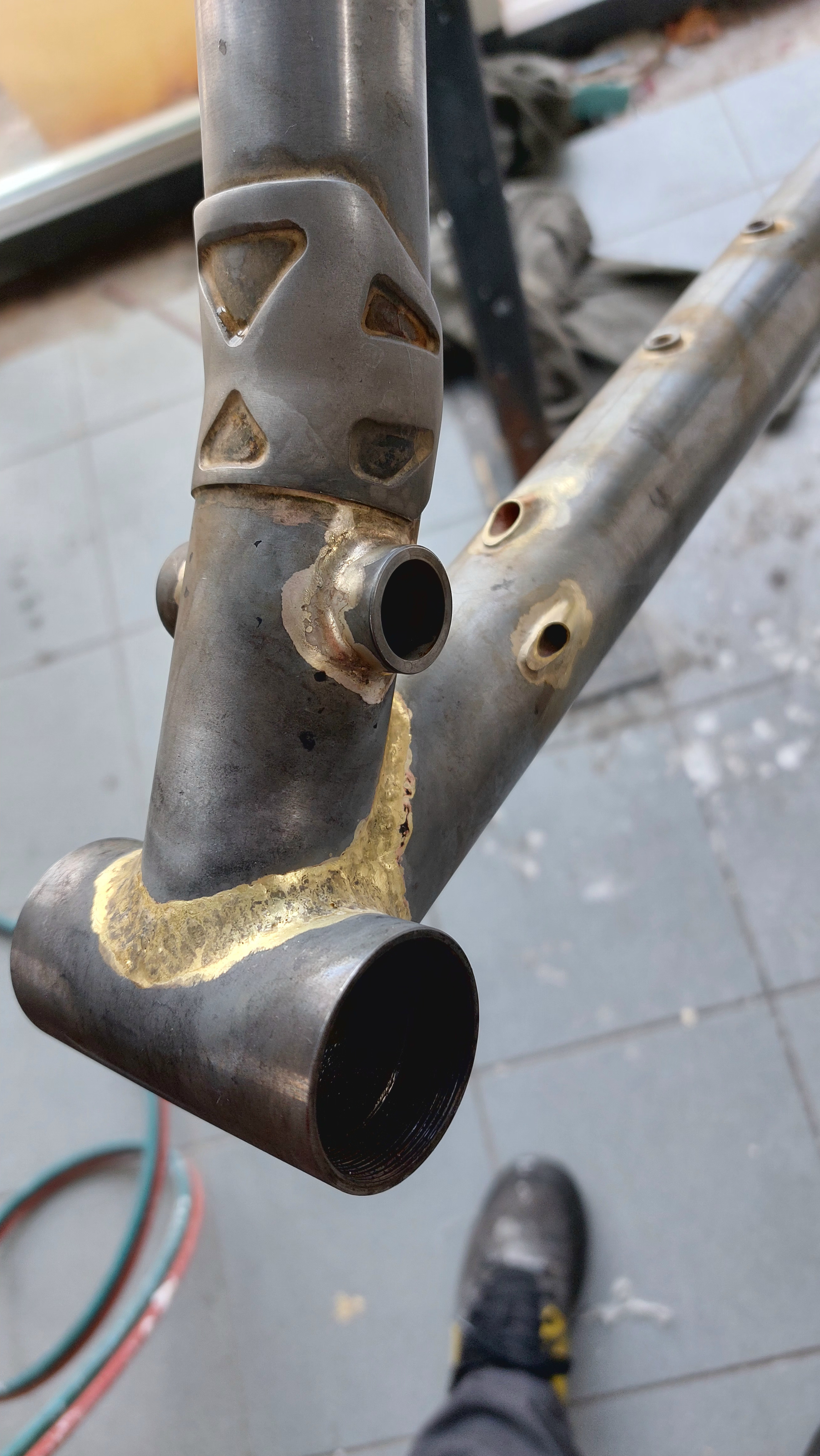
Bearing inner race butts against this (excuse the dirty frame!)

Anyway that’s about all I can think of at the moment, I would like to know how other people have been doing things in more detail so please share!

3 Likes

ive only built three full suspension frames, and the first two failed, so take from that what you will :sweat_smile:, however;

I use replacement bearings from yeti cycles, which have a lip, so I can press them into a bottomless (faced) hole, without needing an interior step, as I don’t have a mill, or a boring head. so I can ream this hole to size and face it with simpler tools, similar to what you’ve done above. I think honestly, getting competent and confident with the mill and boring head is the way to go. I like the idea of cutting both bores from one side, like was specified for BB30, for maximum concentricity.

on my current frame, rather than a preload-length-shaft with a fastener in each end, I push a preload-length hollow shaft (more like a sleeve) through the bearings, and then run one long fastener (pivot bolt) right through the whole assembly.

on a previous frame, I had an internal spacer which was machined ever so slightly smaller than the gap between bearings, which the pivot bolt slipped through, this pressed on the “inside” of the inner races when the bolt was tight (I hope/presume).

I think the oversize bearing with the hollow sleeve is the way to go for me for now, it feels the simplest to make and the cleanest to deal with. ive got a personal full suspension frame third on the list right now, which probably needs a bigger bearing than ive been using, so ill be watching this thread closely.

do you think a similar system to yours could work well with a 44mm bore, and 44mm headset tools?

I also don’t know how much preload is appropriate in a bike suspension system, i’ve always gone with “an absolutely minuscule amount” something around the 0.02mm mark, a basically immeasurable amount.

do I feel like im experiencing excessive bearing wear? not really? but also interested to hear from someone who’s in the know.

Yep I recon you could do the same thing in 44mm. Not sure if the cups will have any issues at the moment though its still an unproven concept!

I think I may have damaged the insert seat in my boring bar once upon a time when I crashed it so step 1 to regaining confidence with the boring head would be a new boring bar I think. It just breaks the insert at the start of the cut at the moment. I think there’s some play in the quill head as it gets further down too which would probably be enough to cause the tiny insert issues.

Would you mind sharing how your frames failed? Might help me/others avoid the same issues. I do wonder if different tube sizing to the standard hardtail rear triangles might be in order. My first bike has 22.2x0.9mm chainstays and 16x1.2mm seatstays, so pretty beefy. It has a springy feel to it that I haven’t felt in other bikes, but it might be because it has some longish sections of plate in the chainstays that could be loading up and springing back under hard corning. The second full squish has 19x0.9mm and 16x0.9mm and it is a bit more flexy, its my wifes bike so I don’t think it will get pushed terribly hard. Its not necessarily bad though either, so long as it lasts fine.

For reference:

Number 1 plate stays:

Number 2

1 Like

I started my fullies with a similar layout as yours, so cups pressed into a housing in the frame. This works pretty OK, and I have 1 fully still making serious milage and working great after 3 years. But I did find it a bit fussy and changing bearings and preloading them was not as good as I wanted. So I moved to a system like BTR and Swarf, where the bearings are clamped in the swingarm. I then just need to cut a hole in the frame and mill a snuggly fitting stainless axle housing that I braze in. Preloading the bearings is very easy as I slide them in the housing, tighten the axle and then tighten the clampbolts on the bearings. OI had a bunch of stainless parts machined through 3dhubs which made them pretty affordable (I think €80,- for a pair)
I have built around 15 full suspension around this system and it works great. I am currently not using any seals on the bearings, but I have made the bearingclamparea wide enough so I could add them. But black oxide bearings from Enduro seem to be pretty durable and weatherproof so far.

I am using 15mm axle for the main pivot and 12 for the rocker, and 6902 28x15x7 bearings. I have room to put in 2 bearings at each side, but I still need to do this to see how it affects the ride.

8 Likes

I have seen a few do it that way, the clamp implementation on those is super tidy. Is there a step on the inside for locating outer race or is it 100% clamping force and its bored all the way through?

There is no step, it just the clamping force that keeps them in place. It was a bit of a gamble, but I didn’t want to add a separate ring on the inside, and I found a couple of examples of other bikes doing it like this. And so far

2 Likes

the first one was a stainless steel front triangle built to accept the yeti infinity link suspension parts and swingarm from a SB5.5,

I was recently not a student, and still as broke as one, and build it out of stainless because I thought it would be cool, and 304 hand rail tube was cheap. I got sick of chasing cracks around all the fittings and weld corners and then I retired it when a crack around the top tube (at the head tube gusset) got really quite big before I saw it. I decided it was dangerous to keep riding it, and id moved on from the geometry anyway.

the second one failed catastrophically. I wasn’t there but by all accounts, a buddy of mine cased a big jump, and ;

a) snapped the downtube where id mounted the upper eye of the shock using a doubler plate on a 38mm x 0.7mm section of a butted 4130 downtube.

b) buckled the seat tube, between the main pivot and the BB shell, iirc, it had a dropper post in it down to the mount so that no great surprise. seat tube would’ve been ~0.8mm wall at that point, 31.6 ID 4130

c) tore the top tube in half, just behind the tt/ht/dt gusset. that would’ve been 32mm ~0.8mm

it was pretty gnarly looking, my buddy was fine, If I had to guess, id say not enough downtube by a long shot for that kind of riding (it had a fox 40) , ESPECECIALLY not to have the shock mounted to the middle of the downtube, that’s now a no-no for me I think. .

I learnt a lot from seeing that bike go,

Ive since used a 44.45mm OD X 0.9mm straight gauge downtube, and didn’t mount anything to it, on my long and rowdy 140mm trail bike. id do this again, or mount the shock eye just in the corner by the BB shell.

5 Likes

In 2014 I built my first full suspension frame using a 44mm headtube and two upper cups as the main pivot. I’ve build several frames using this method.


This works well. I split the clamps that clamp onto the old stub of steer tube that I used as the main shaft. The shaft as a starnut pressed into each end and I used headseat top caps on each end to tighten preload.

11 Likes

awesome, that’s exactly what I wanted to see.

1 Like