I’ve been interested in making a partially-carbon frame as a bit of a learning experiment. It seems like the simplest way to dip my toes in would be to use metal-lugged construction with off-the-shelf round carbon tubing. I’d keep the head tube, down tube, and chainstays metal but use carbon for the top tube, seat mast, and seat stays.
Big questions I have are:
What sort of gap should I design for with the “lugs”?
What tubing diameters/wall thickness to use?
Is there a good place to source this tubing?
What sort of weave/layup is best for these tubes?
What is a good epoxy to use? Do I need additives to address potential corrosion issues?
Is it feasible to powder coat the metal part of the frame before installing the carbon?
Is there substantial difference between bonding to 4130 steel, 316 stainless, or 6-4 titanium?
I’m off to do my own research and will post what I find here!
What sort of gap should I design for with the “lugs”?
From my research, it looks like folks recommend 0.008” to 0.013" [0.20-0.33mm] per side. It’s recommended to prep the metals and composites with ~120grit sand paper prior to bonding. I also didn’t think about bond length - I’ve seen recommendations for 2-3x the ID which seems quite long for bicycle tubing.
What tubing diameters/wall thickness to use?
Rock West has some suggestions on their site:
Top Tube
Ø1.248 x 0.123in (Ø31.70 x 3.12mm)
Ø1.3 x 0.12in (Ø33.02 x 3.0mm)
Ø1.4 x 0.136in (Ø35.56 x 3.45mm)
Seat Mast
Ø1.374 x 0.131in (Ø34.90 x 3.33mm)
Seat Stays
Ø0.647 x 0.096in (Ø16.43 x 2.44mm)
Ø0.551 x 0.091in (Ø14.00 x 2.31mm)
There’s also a large table of options that don’t appear on their site.
Is there a good place to source this tubing?
A lot of folks recommend Rock West Composites. I’ve also seen people who like M-Carbo. DragonPlate has a number of good options but doesn’t seem to have much direct industry usage.
What is a good epoxy to use? Do I need additives to address potential corrosion issues?
3M DP420 seems to be the most recommended. Additives act as “bond line controllers” so it’s less about corrosion prevention and more making sure the parts don’t actually touch.
I think the general consensus is that wrapped mitred tubes is the simplest method for carbon. I too would be interested to pool some resources and info, both for pure carbon frames and carbon/metal hybrids. Presumably you can wrap carbon to metal the same way you would carbon to carbon, once you’ve dealt with the whole corrosion issue.
Just yesterday I came across Coll Carbonworks, who offer(ed) ready-to-use chainstays, seatstays, dropouts and main tubes. Sadly they seem to be sold out of everything, their FB page is dead and their instagram hasn’t seen a new post in 3 years. Edit: as of 2/11/23, Coll’s website no longer works either.
I’ve played around with this topic during my time at university, here are a few things I remember having found out (sometimes the hard way…):
The gap required really depends on the type of adhesive you use. It has to do with the relationship between the adhesive’s capability to adhere to the substrate’s surfaces vs. its internal strength.
some adhesives come with particles suspended in them to ensure a minimum bond thickness is achieved (Araldite has a few of those)
the technique to prep and execute the bond needs to be practised. I did some joints and tensile tested them afterwards and was quite surprised by the variation of the results in the beginning. It got better with practise.
the viscosity of the adhesive in its uncured state is quite important for your curing situation (standing upright, laying flat…). Too thick and you will push some of the adhesive away while inserting the tube resulting in insufficient bonding surface, too thin and it will run away before it cures properly. Thickness can be adjusted by adding some filler material like micro balloons powder.
sticking a tube into a hole is not the ideal way to connect two surfaces to be bonded, since it “shears” the uncured adhesive and can result in areas where the adhesive is scraped away. It helps to apply the adhesive to both surfaces. I had more consistent results doing it this way.
bond length can be roughly calculated by the shear strength of the adhesive and the bonding surface area. This should obviously be larger than the tensile strength of your tube (or the lug, whichever is lower)
That’s all I can remember from the top of my head, I hope it helps you a bit!
Great topic. I actually just started playing around and started to design a tube set including dropouts that looks good and could be manufactured at a reasonable cost. For now it is not much more than a thought experiment, but I’d be excited to see more carbon builds.
I agree with the statements from @Luniz82 and would like to add another important factor, which is thermal expansion. The longer your bonded joint between disimilar materials the more of a distance the bond line has to compensate. This can result in very high shear forces. With a double lap joint you can improve this a lot, but on the other hand you will have a more aprubt transition in stiffness, which is not desirable either.
So all in all it is a fairly complex topic and while I’m lusting after an Atherton or Bastion bike, I’d also consider a tube to tube construction with overwrapped joints like my road bike i built in the past.
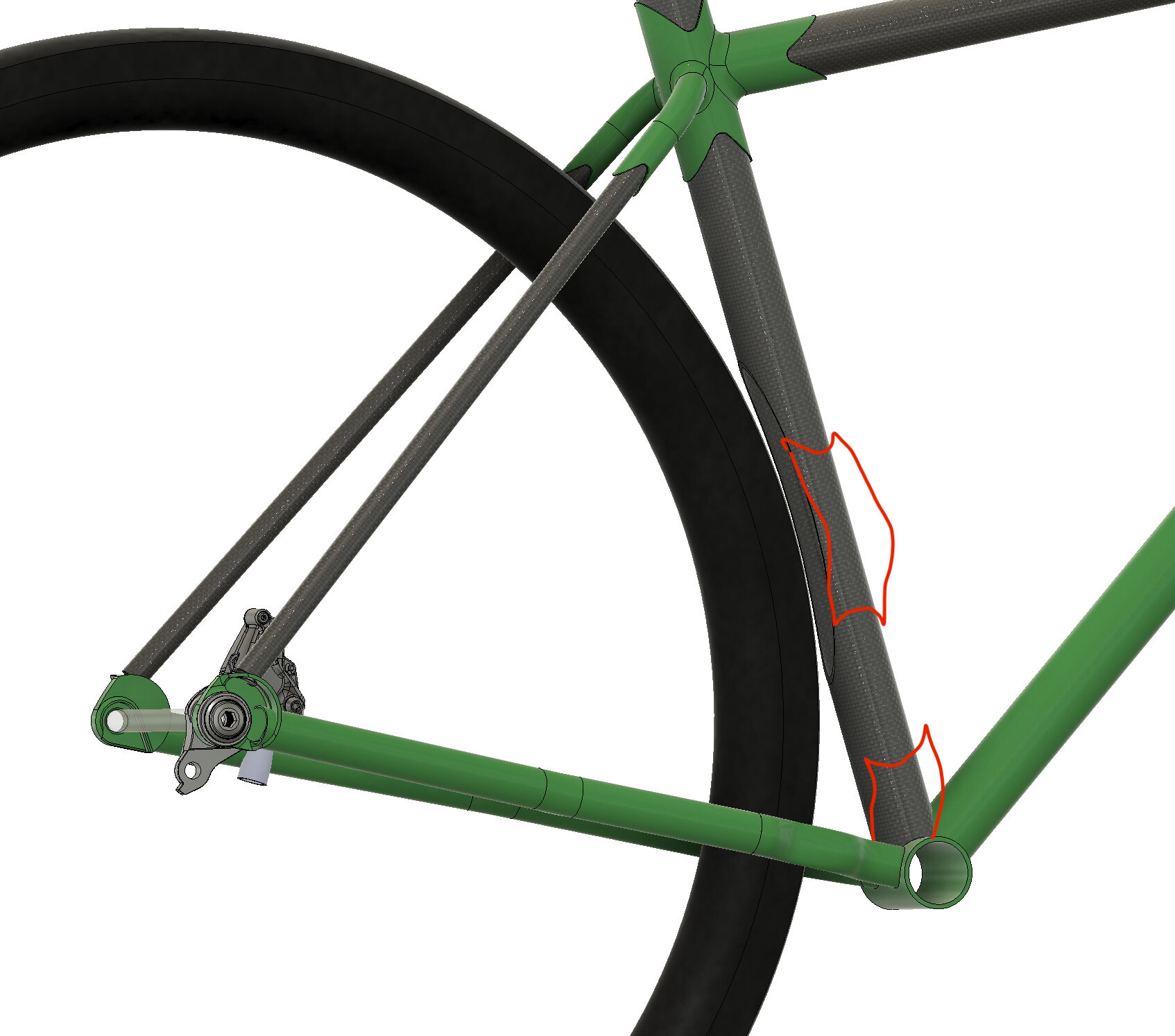
One issue I ran into on designing this bike is clearance between the seat mast and the rear tire. I’d like to keep the chainstays < 435mm with 29x2.1" tires and unfortunately that means issues with tire clearance. I’m curious what folks think the best way to remedy this would be. My thoughts so far:
Cut out a section of the seat mast (as shown above) and hand-wrap reinforcing fiber around the cutout
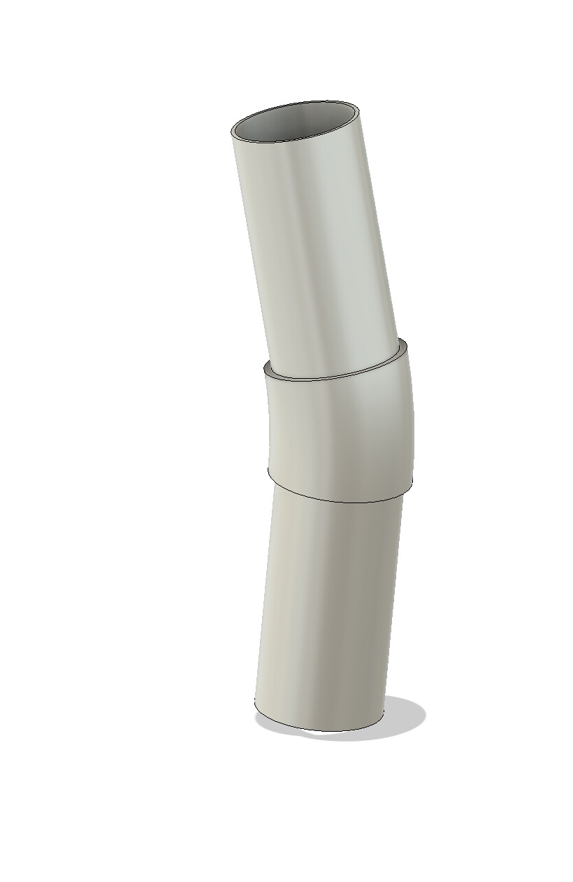
Cut the seat mast in two and do an angled butt joint for a bend
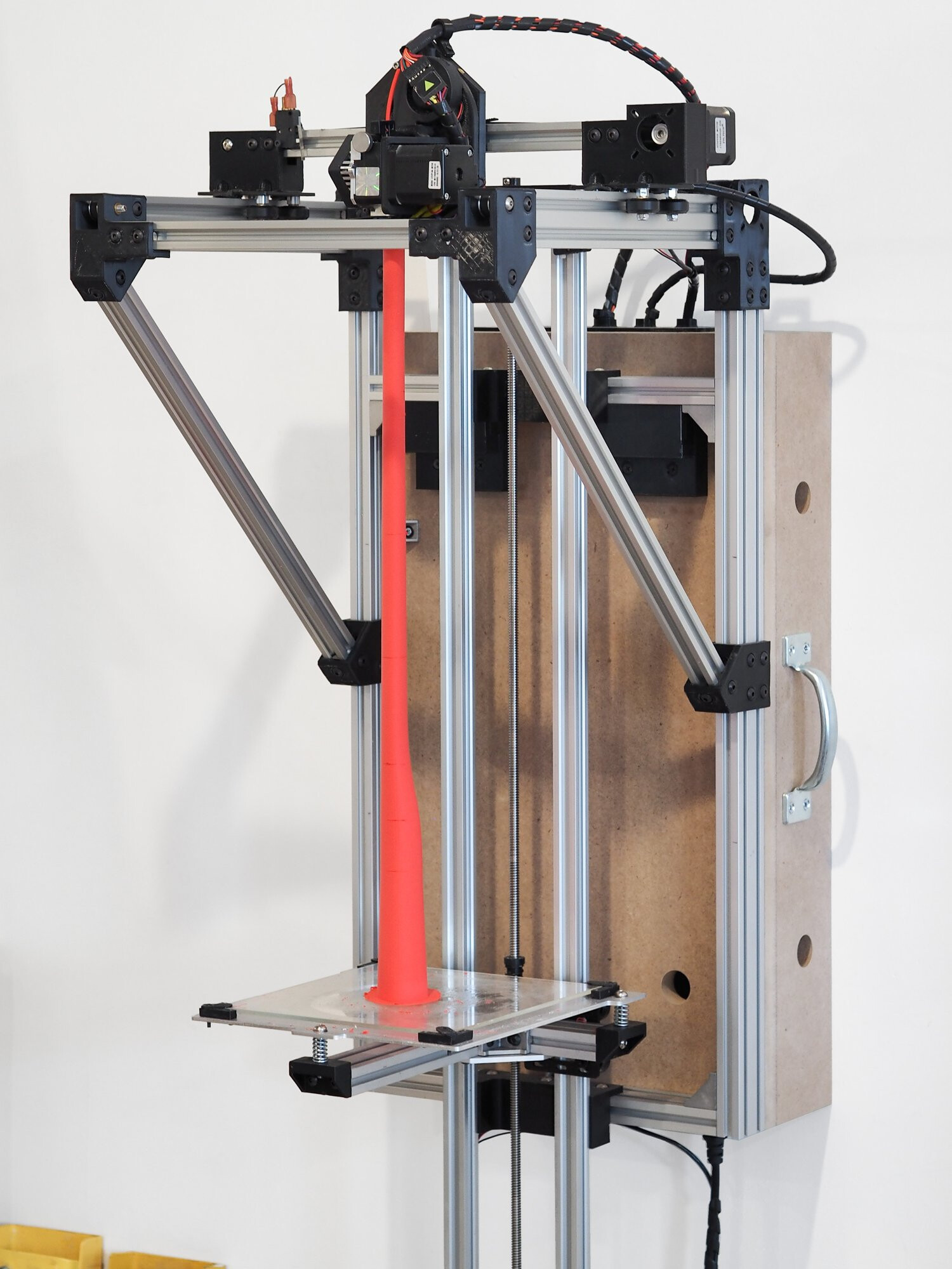
If you want to learn a bit more about making complex tubes, check out Easy Composites on Youtube. They have videos on split-moulded tubes and also melt-out mandrel tubes. Both are a bit beyond a simple DIY job but it you have a decent workspace and some knowhow you could do either. You could also consider chopping a suitable tube out of an existing frame, but obviously you’d need to find a frame that could be sacrificed.
as long as you are 3D printing stuff, why not 3D print a bend lug. Either placed up in the middle of the tube, or placed at the BB joint to kind of offset the seat tube forward?
That’s definitely an option! I’m trying to minimize the lug-age (and resultant weight) but a little angle bracket could be an elegant solution to this problem.
That’s a great point! There won’t be a dropper on this frame since I’m using a seat mast, but it would be a quick and easy way to offset the seat tube. I think it’ll come down to material cost as the BB lug would have to be Ti and the mid-seat mast lug could be aluminum.
Ben from July Cycles: Process — July Bicycles has a really novel way of using 3D printed mandrels to form complex tube shapes. I think he bolts them together somehow so they can be pulled apart once the tube is cured.
He was open to collaborating. A seat tube with a cutout would probably enable some new designs. Seat tube - front derailleur - tire clearance is already getting pushed to the limit. The new trends of 700x32 and 700x50 have trouble clearing with short chainstays (415 and 425 respectively)
A carbon ST with a cutout and “braze-on style” front derailleur mount would solve the interference issues.
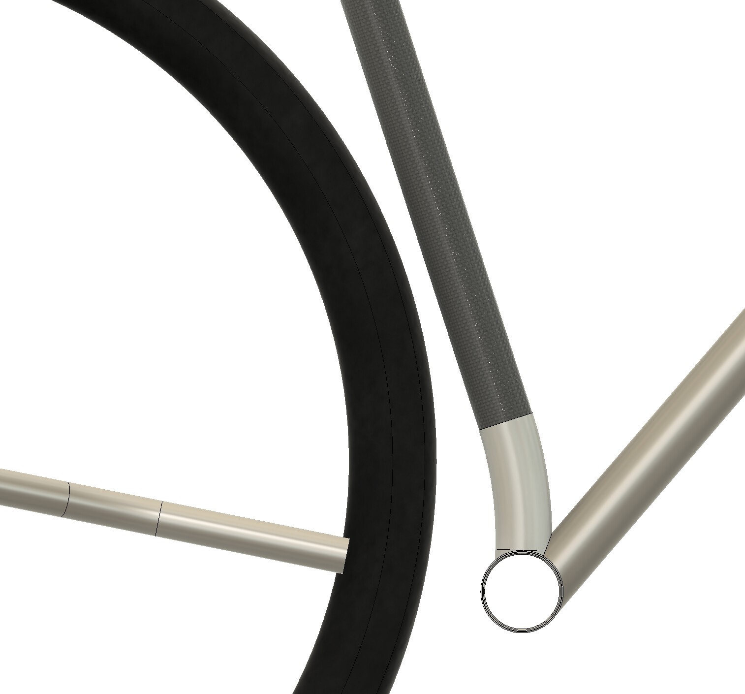
That would be slick! Maybe next iteration of this frame I’ll try that but I’m hoping to keep it pretty simple this go-around. In the spirit of simplicity, I think a low bend would ultimately be the easiest way to get the desired offset and without the added cost of 3D printing - it can just be a stock tube with its end turned down.
I finally found a bit of research on lugged metal-CF construction in this paper (PDF attached below).
Key takeaways seem to be:
Bond gap is very important, shear strength will decrease if larger or smaller than ideal
Surface texture should be rough (400-600 grit), but shouldn’t be overly coarse (eg knurled finish)
Breaking tensile force has an approximate linear relationship with bond length (and thus surface area)
Nothing too earth-shattering, but it was interesting to me to see the linear relationship between bond length and ultimate tensile force.
Going off of the DP420 datasheet, the shear strength is listed as 4500psi (= 31N/mm^2). As an example, the seat mast in the above photo has an ID of 31.57mm so a 50mm bond length would have a surface area of π*31.57*50 = 4960mm^2. That would ostensibly support a force of 154kN which is huge! To put that in perspective, I’m about 75kg so sitting statically on the seatmast with no other tubes involved would put about 740N of force on that joint. That’s about 1/200 of the rated force.
Now if you dive deeper into the tech data for any epoxy, it’s clear that the “headline” shear strength is not necessarily applicable to every material. The DP420 tech sheet for example lists fiber-reinforced plastic at 1100psi if prepared properly, so about 25% of the ideal shear strength for aluminum, but still quite good for bicycle applications!
I chatted a bit about this with Johnathan at Framework Bikes who specializes in lugged carbon construction. He recommended this YouTube video for a primer on adhesive construction with composites. I’ve already learned a ton from it!
Perhaps most interesting was the bit around 1:09 that dove into why increasing bond length does not linearly increase joint strength. So my above statement about extrapolating the given shear strength for an epoxy to a larger surface area might not hold up.
The next most interesting bit is around 1:48 where he goes into detail about joint design with that above constraint in mind. There’s no real “answer” for how to design an ideal overlap, but some good data for sure!
It was also interesting to hear just how crucial the surface prep, environment, and dispensing/application process is to success of the joint. Now obviously we’re out here building bicycles and not aircraft fuselages, but it could be argued that we likely work with thinner margins than Boeing.
This got me thinking about additively manufactured parts, especially as I consider whether single- or double-lap joints make more sense. From most sources I’ve been able to find, a post-processed titanium printed part will have an Ra (average roughness) of 5-9µm and an Rz (peak-to-peak roughness) of 20-50µm. Compared to the standard recommendation of 400 grit joint preparation which corresponds to ~0.23µm, that’s quite rough.
You are going so hard on this! I’m so glad you’re sharing what you learn along the way. I might not use carbon in my next build, (or the next 5-10 after that) but I want to try using it. This is supremely helpful.