Roast my travel bike design inspired by the English FGC/FRC

For my frame #2 I want to build a foldable “travel” bike. Since I could not come up with a design for splitting the shift cable/brake hose that I fully love, I’m thinking about something more in the direction of Rob English’s Folding Bike Concept.

I’ve come up with this design so far - everything yellow is attached to the front triangle, everything grey to the rear:
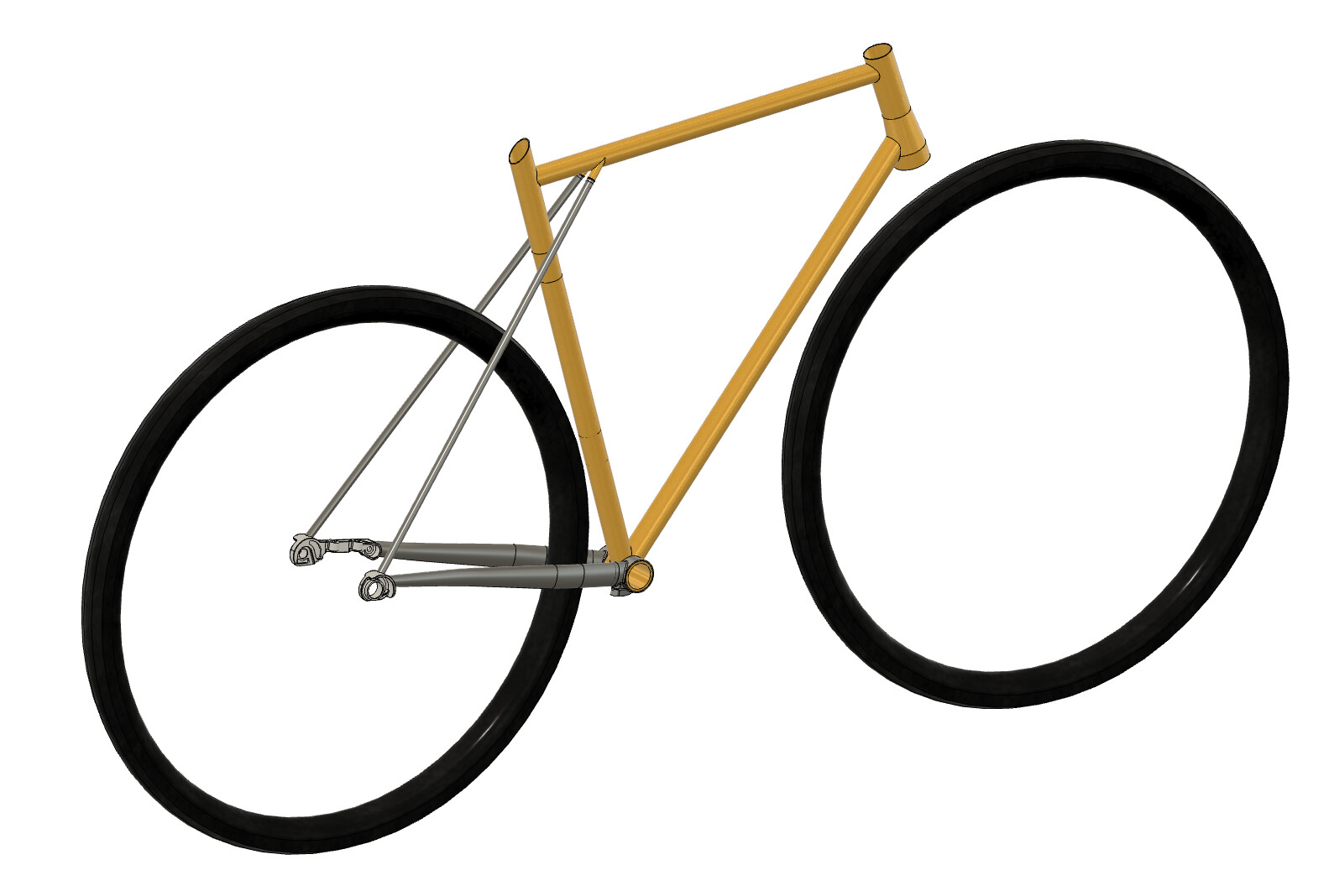
Since I would like to minimise how much the cables need to bend, the rear triangle would fold up-and-forward, instead of down-and-forward. That also allows to seat stays to be brazed to the dropouts instead of needing another bolted joint or pivot there. I’m counting on the flex of the stays to maneuver them around the little nubs on the top tube.

The shift cable/brake hose would run semi-internally, coming out of the DT and entering the CSs after the BB, similar to what I did on my first frame:
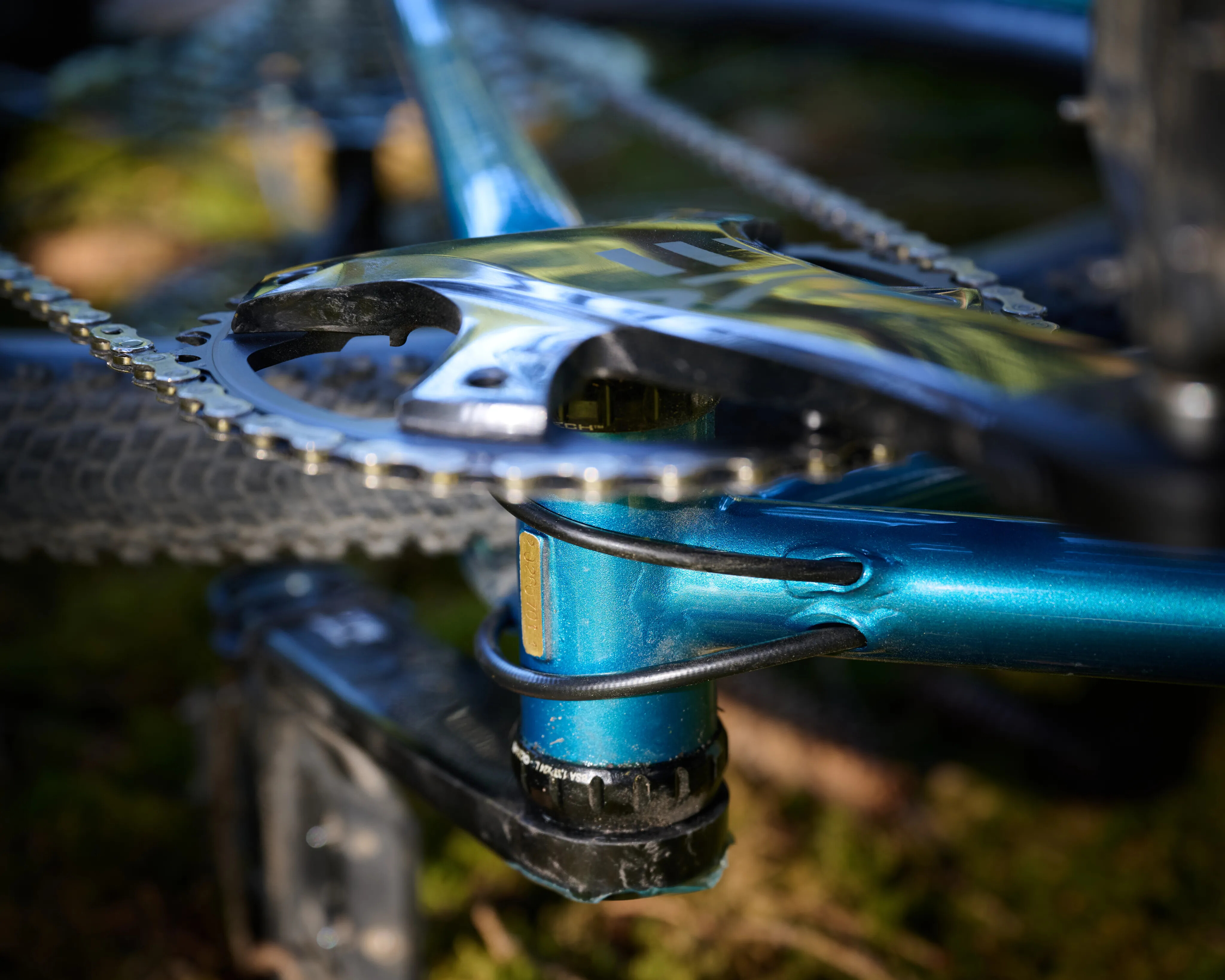
I’ll need to use wider guide tubes so the cable and hose can slide more easily (and also do a better job getting the braze to flow onto the DT and BB^^), but I’m reasonably confident that this would work out.

Now the parts I’m doubtful about:

1: The hinge around the BB

So far, I’ve modeled the hinge as a 3D-printed lug that clamps directly to the BB:
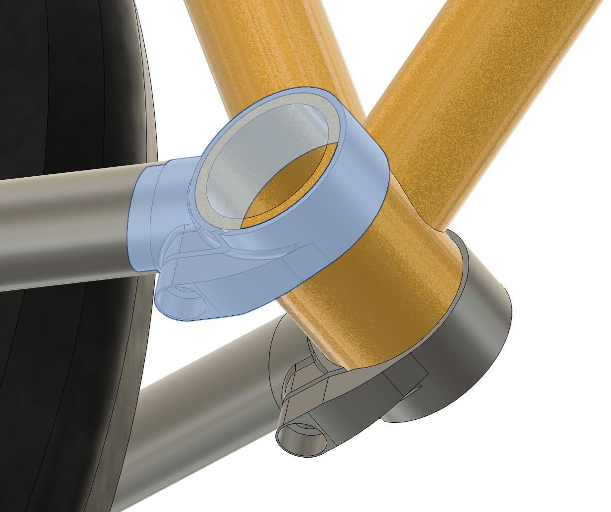
This is what I’m wondering about down there:

  • Do I need a bearing surface in-between the lug and the BB?
  • Should I add a bolt that runs in a slot in the lug to keep in from sliding left and right?
  • My clamping slot is not perpendicular to the tangent where it meets the BB - is that a terrible idea?
  • Is using a 316L stainless 3D print as a clamp a bad idea in general?

2: The SS-TT connectors

The connection between SS and TT is made by a pair of cup/cone inserts (for want of a lathe also 3D printed) that are brazed into the stays (highlighted in the rear) and into short, mitred sections of tube that are then brazed to the TT (highlighted in front). The bottom cone is threaded for an M5 bolt and the TT would be slotted so that bolt could be reached with an Allen key (the slot is currently not modelled).

Here’s what I’m scratching my head about with this part of the design:

  • The SSs meet the TT within its butted region. Should I add a reinforcing sleeve there nevertheless?
  • Is the access-slot from the top a terrible idea?
  • Does this order of operations for brazing seem reasonable?
    • bolt the cup/cone connectors together
    • insert them into the tubes, but don’t braze them in
    • tack the stay to the dropout and the short tube section to the TT
    • remove the cup/cone assembly, drill a breather hole and the access slot into the TT through the short section of tube
    • silver-braze the cup/cone into their place
    • braze the stay to the dropout and the short tube to the TT (with or without the bolt connecting cup/cone?)

What do you think about this design? Is there anything that stands out as a particularly bone-headed idea (incl. things I haven’t mentioned)? Anything I could do to make my life easier while building the thing?

Thanks in advance for your time and help!

6 Likes

Nice design but still a few details to figure out. I don’t have much to add but maybe take a look at this blog post by @drwelby. He seems to have tackled a very similar project recently and came up with some clever solutions. Good luck!

2 Likes

I cannot answer all of your questions. Never done a folder.

I’d be tempted to braze on some stainless sleeves to the shoulders of the bb shell that the clamp rings can rotate on without marring the paint.

I’m not an expert, but I believe it’s challenging to include threads in a 3d-printed part. If you’re dedicated to the idea of 3d printing this part, I’d look into a bolt and barrel nut solution.

Another idea would be to ditch the 3d printed clamp rings and fab something yourself from steel. You might be able to find an off-the-shelf tube size with an inner diameter that slips perfectly over the above-mentioned stainless sleeve. Then braze on some M6 binders on the opposite side of where you attach the chainstays. Maybe two binders per side for a wider clamping surface. Could be overkill though.

I personally wouldn’t run the chainstays directly into the top tube unless you reinforce the top tube. You could use a really thick butted top tube instead but a reinforcing ring integrated into the 3d printed part would be lighter.

For the SS/TT connection you could make some 3d printed nubs that stick out from the top tube with a shoulder on the nubs that’s the diameter of the seat stays. Then add small binders and slots to the stays like the top of a seat tube clamps a seat post. The stays can slip over the nubs and bottom out on the shoulders and then you tighten the binder bolts. Seat stays are really only ever compressed, so I doubt you’d need to go too large for the binders there.

3 Likes

Thanks for sharing that post!

Having the seat tube pivot with the rear triangle is a neat idea :star_struck:. That particular design would have the added benefit of allowing me to use a short down tube that I ordered by mistake. I’ll have to riddle out how I can disguise the hinge, though - I’m just really tickled by the idea of rocking up at the train station, packing my bike and hearing someone whisper “oh it folds!” (real mature motivation, I know^^).
Also, if I can make the dropouts meet the seat post binder, that’s another potential easter egg I love (albeit maybe slightly less useful with through axles than it would be with skewers).

1 Like

Thanks a lot for your thoughts!

If I decide to paint the frame, I suppose you’re right that the stainless sleeves will be a must. I was toying with the idea of a cold-blued + Multi Film (or beeswax) finish, but haven’t decided yet. Even then, the stainless sleeves would help - the folding would rub off the protective coat and since it’s not meant to move while riding, I don’t want to grease the pivot, so I might end up with a very rusty BB.

For the threaded 3D printed parts, I forgot to mention that I’d have the parts printed with holes that I would then tap the old-fashioned way.

A collar made from a tube section and a binder is most certainly the more reasonable (and probably lighter) design. I came up with the one I have above in the quest to hide the binder a bit more, but I don’t fully love it. Yesterday I modelled the CS bridge (which has to be bent to clear the ST when folded) and with that in, I thought that regular binders would look less out of place than my design.

I appreciate you reinforcing the sensible voice in my head that says to sleeve the TT at the SS/TT joint. It would probably also help with the cutout on the top being less of an issue.

I thought about having binders on outside of the SSs, but find that less elegant than the hidden bolts in my design above. If I were comfortable with the bend in the cables when folding the rear triangle downwards, I would just go with a wishbone stay design that has the bolt inside the “stem” of the wishbone-Y (i.e. what @englishcycles does on many frames).

I have never made a folder. Heck i haven’t even made a metal bike at all, so take my advice with a pinch of salt…

The top tube seat tube connection sees a lot of sweat dripping over it, so if you have holes there and bolt heads i would make sure nothing can pool anywhere, as i think that could get crusty rusty quickly.

Then another thing I honestly have no idea if it is an issue or not, but i think better to raise: your seat stays are very long and you cannot have any sort of bridge in them, and i would calculate the buckling failure load on them. Especially as there is also a pivot on the BB instead of a ridgid connection that would potentially reduce the compression load on this frame member, and the brake torque that also wants to bend things.

1 Like

Oh, I didn’t think to account for rider-supplied salt water ingress. For the bolts and threads I’d hope that should be fine since they’d be stainless, but having the sweat run down the inside of the tube and collecting near the BB sounds less good. Should be mitigated by having the cones pointing upwards, though.

I also wondered about the buckling stress (even more so since I am toying with the thought of using ridiculously thin 10x0.8 mm tubes for seat stays), but forgot to add that to the post. I’ll have to research how to calculate a sensible number there.

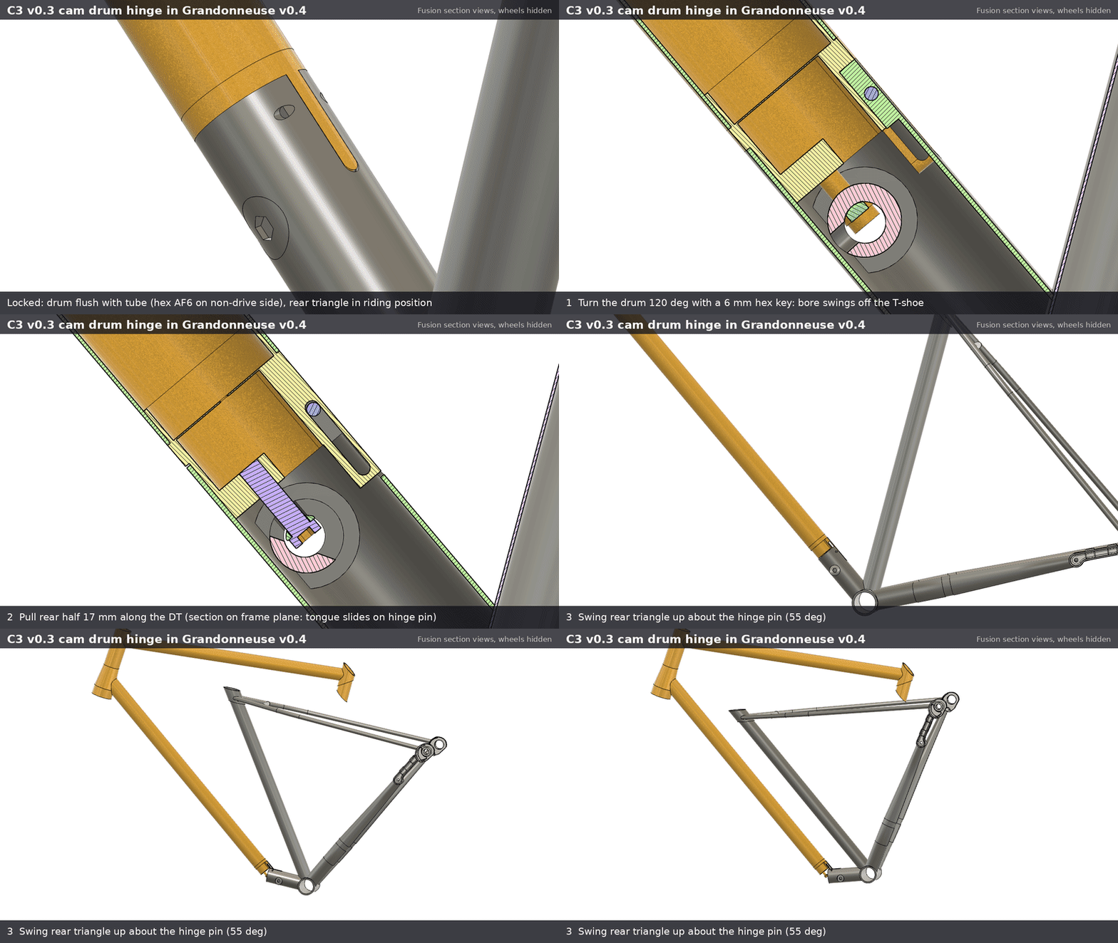
I liked the joint on the DT in @drwelby’s design that @bushtrucker shared, but completely ignored the laudable practicality-first ethos of that blog post and came up with this idea:

dt_hinge_c3_v03_operation

The preload comes from a cam mechanism, the stiffness from the faces of the two tubes fitting together. Even though in theory, it should stay put once in its locked state, I’d also add a bolt to keep the two halves together once preloaded.

Surprisingly, getting the two connectors machined would cost “only” ~120 EUR, and the cam is something I’d trust myself to make (allowing for a few scrapped parts).

When folded until the SS-connector-sleeve almost touches the DT, the dropouts sit neatly next to the seat post clamp, which might allow for a clever locking mechanism :star_struck:.

If I go for this design, I’ll probably replace the split seat tube with an integrated seat mast that’s removable (carbon tube, clamped at the BB, the SSs and the TT joint).

Now, I realise that’s a completely different question, but is there anything that stands out as a terrible idea in this approach?

1 Like

Yeah with stainless fasteners in stainless you will need an anti fretting compound anyway, which should already help with the crustyness.

1 Like