I am starting on my second full suspension bike build and wanted to get some feedback on 3D printed parts. Through my work I’m somewhat familiar with parts printed in 316L and titanium, but I have a few specific questions that I hope some more experienced and technically minded folks can help me answer.
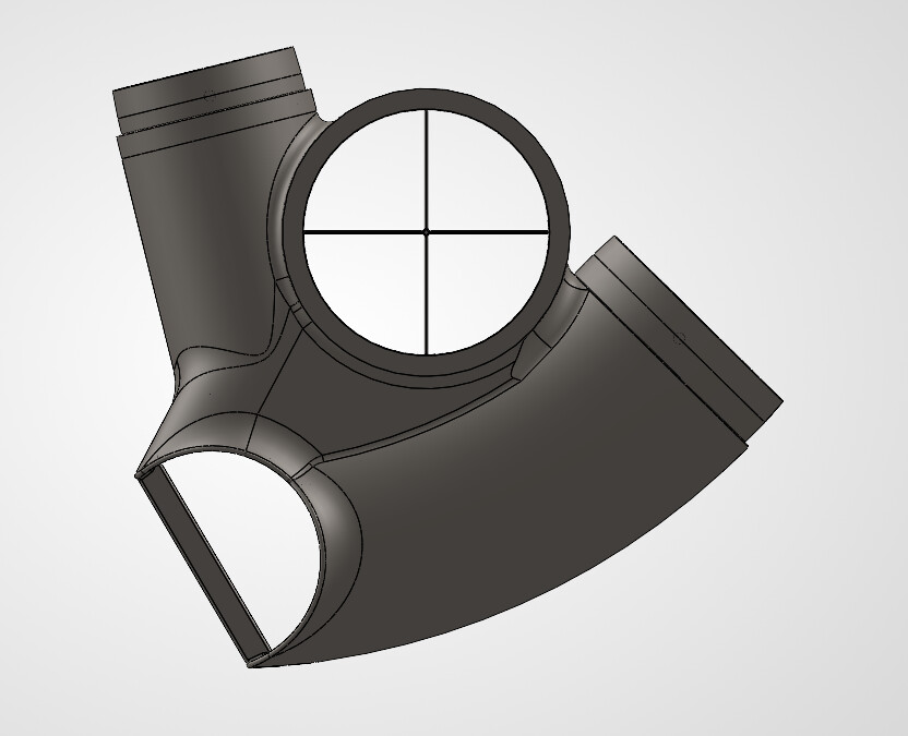
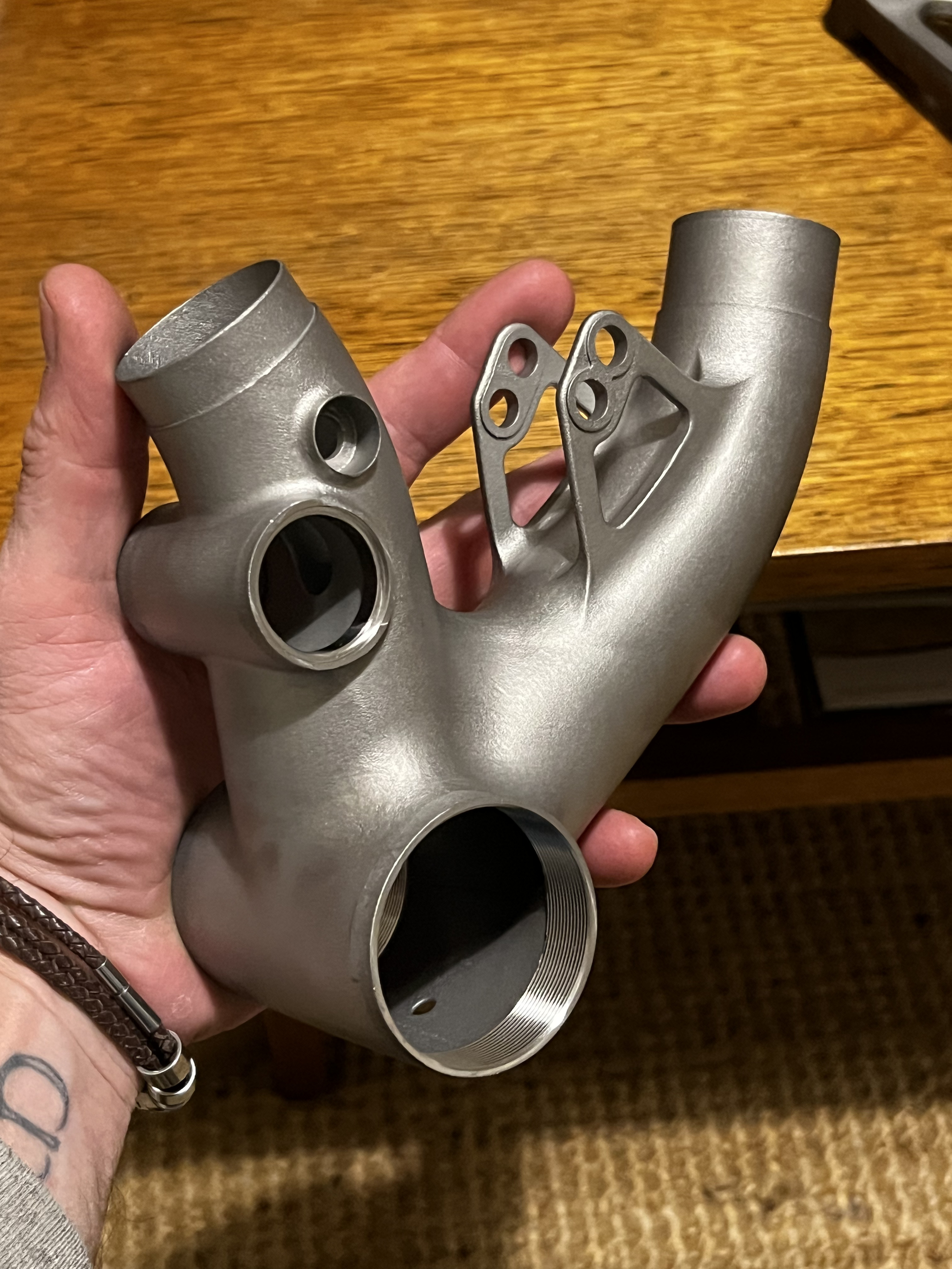
The part I am printing is a BB shell/main pivot cluster, It will be printed in 316 stainless steel with a post print heat treat, a traditional machined BB shell will be welded onto this:
From the parts I’ve seen at work, I know that warping is a factor, and in an attempt to combat this I’ve added some bracing struts that I will cut out after getting the print. My specific questions are:
given that the print has support structures built around it as part of the printing process, are my additional struts actually doing anything to help maintain the intended dimensions?
does most of the warping occur in the printing process, or in the heat treat; and will having the struts in place for the heat treat combat some warpage?
the main pivot uses a ZS44 headset cup, and I plan to machine this surface to exact dimensions later. I’ve undersized the opening in the print to 43.5mm. Will .5mm be enough tolerance here or should I undersize even more?
If the printing supports are anything like what you get with desktop plastic printers, they won’t be attached to the model robustly enough to withstand any warping - I’d leave your extra bracing in place. Plus the manufacturer will likely remove the printing supports before the heat treat, but since the extras are designed into the model they won’t touch them.
I see lots of builders print these types of supports into the part how you have it, but I haven’t done so and haven’t had meaningful warping issues on any surface I’m post machining anyway. I’m sure some warping is occuring, but if the circularity really matters i’m gonna machine it. I print my BB cluster very similarly to what you have here with no braces at the tube joints and the tubes fit perfectly. I think It’s helped by the fact that a thin wall bike tube doesn’t have to be perfectly circular to begin with, so mating up to the part shouldn’t be an issue.
My guess is the heat treat cycle does the real work here. No experience on whether the braces help, but I would imagine they do.
I go .5mm undersized on my 52mm bearing seats and it’s perfect. I don’t think you’ll have any need to go more undersized.
I think the upper of your two holes will be fine - the large rigid structure will support the thin-walled section quite well. The lower half-hole might be more vulnerable as it’s a fish mouth shape and may be prone to the thinner points cooling much faster than the bulk of the lug. [tested with eyeball-FEA v1.0]
Thicker into thin sections will have the thin sections pull out of shape as teh thicker shapes swell and cool with heat on both printing and heat treatment. I would allow machining tollerance in the pivot bore and also some material to remove to fit the BB shell. Putting bracing in will always be an advantage though there is the extra work of removing them.
Another option is to print the BB shell as one part of teh assembly and get the producer to cnc the threads in. I designed the bb shell where the theads are 6mm thick and then left it them to machine it to T47 after heat treatment.. I have never had cups thread in so smooth. It was beautiful. They also machine the pivot bore to take bearings. Cost was Aus$160 to machine on top of the Aus$400 part but worth it in my opinion. Everything was dead square and it was up to my jig being accurate to transfer the alignment to the rear end.
Yes, i should’ve mentioned this, but this is what I ended up with in my process as well. IMO, the cost increase of having it made/machined as one piece is well worth it. You take out the risk of messing up welding your $400 part to a $20 shell, you don’t have to machine the shell for vent holes/cable routing, you gain design flexibility in the shapes, can add generous fillets, etc. If i were looking for every way to reduce cost I’d reconsider but at my volume, it’s a no brainer.
Keep in mind, having them machine it shifts the risk onto them as well- if they bungle the threads, they make you a new part. If you weld the BB shell on backwards once, you just paid for quite a few machining post-ops
Thanks everyone for the feedback. Great info as I’ve come to expect from the forum.
I will look into having threads machined by the printer, but I’m not sure if they will offer that service. As I am a ways off from being able to sell my services as a framebuilder, I may have to take the cheaper/hard way, just to keep the project in my budget. I’ll try to follow up with results when I get the part but timing is dependant on when we place the next order for work
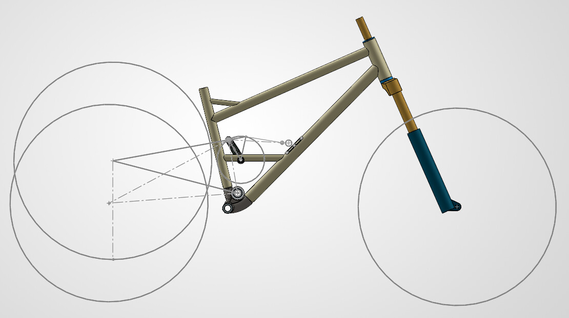
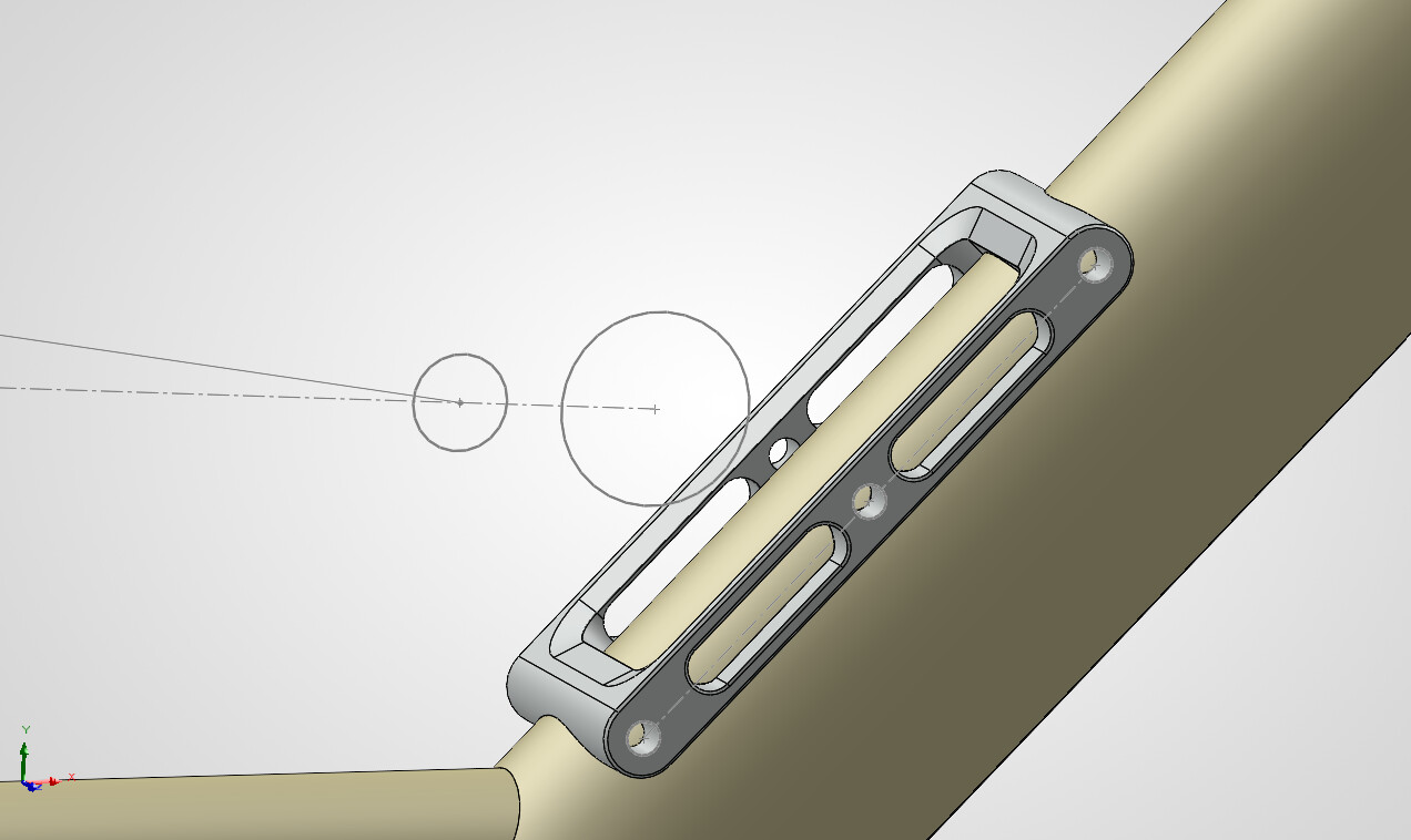
will have 161.24356789~mm rear travel with a 230x65 shock. Another part I am considering printing is a piece to allow swappable bolt on shock mounts on the downtube. That part currently looks like this:
As it is, the mounting plates would attach with 3 M5 bolts per side, but only about 5mm of thread depth in the part. I’m not sure if that is strong enough. I am also wondering what you all think of the large weld patch this piece will create on the tube? Am I risking too much heat into a high stress part of the tube?
I think you’ll be ok with the structure. Rather than weld the full length of the bracket just put a 10mm long weld at each end. You are mostly pushing into the weld rather than tear it apart with the forces. Other option is to braze it on. Bronze or silver with a micro fillet along the whole edge will be plenty strong enough.
I machined out the bore on my main pivot this weekend and had another question regarding 3D parts: Is a printed part of the same material and alloy as a billet machined part harder on your tool?
I avoided using the hand reamer and facer on my part, mainly because of part deformation, I thought I would get a better aligned bore by setting it up and machining it, but partly out of concern for damaging the (expensive) hand tools.
Is this concern unfounded?
Additionally, I have had experience with tapping in 3D printed titanium and 316L steel. While the steel generally taps fine, our shop has broken numerous taps in 3D ti pieces. When asking Emuge support about the best taps to use, they said 3D printed stuff was more difficult to tap, and we’ve since moved to paying the printer to tap ti parts for us.