Asking the hivemind here! I am frequently designing 3D printable parts (dropouts, yokes etc) in Fusion360. My way to do this usuallhy to start from a sketch, loft some shapes together, cut out shapes where I need room (chainrings for instance) and then when I have a nice solid I try to use the Shell command to make it with 1 or 1.2 mm walls. (And after that I usually add extra structures for stifness etc) However, more often than not the frikking shell command gives an error. “could not create a valid result” Even when I think I have a simple shape (rectangle lofted to oval) Fusion just refuses to Shell it with 1mm thickness. It will do it with 0.2mm, but nothing more… My go to plan now is to slice the volume up in parts, shell the parts until I find the parts that won’t shell and then mess around with extrusions and substractions until I have something that is close enough to the desired result.
But I feel there must be a better/easier way to make a simple yoke. What do I do wrong?
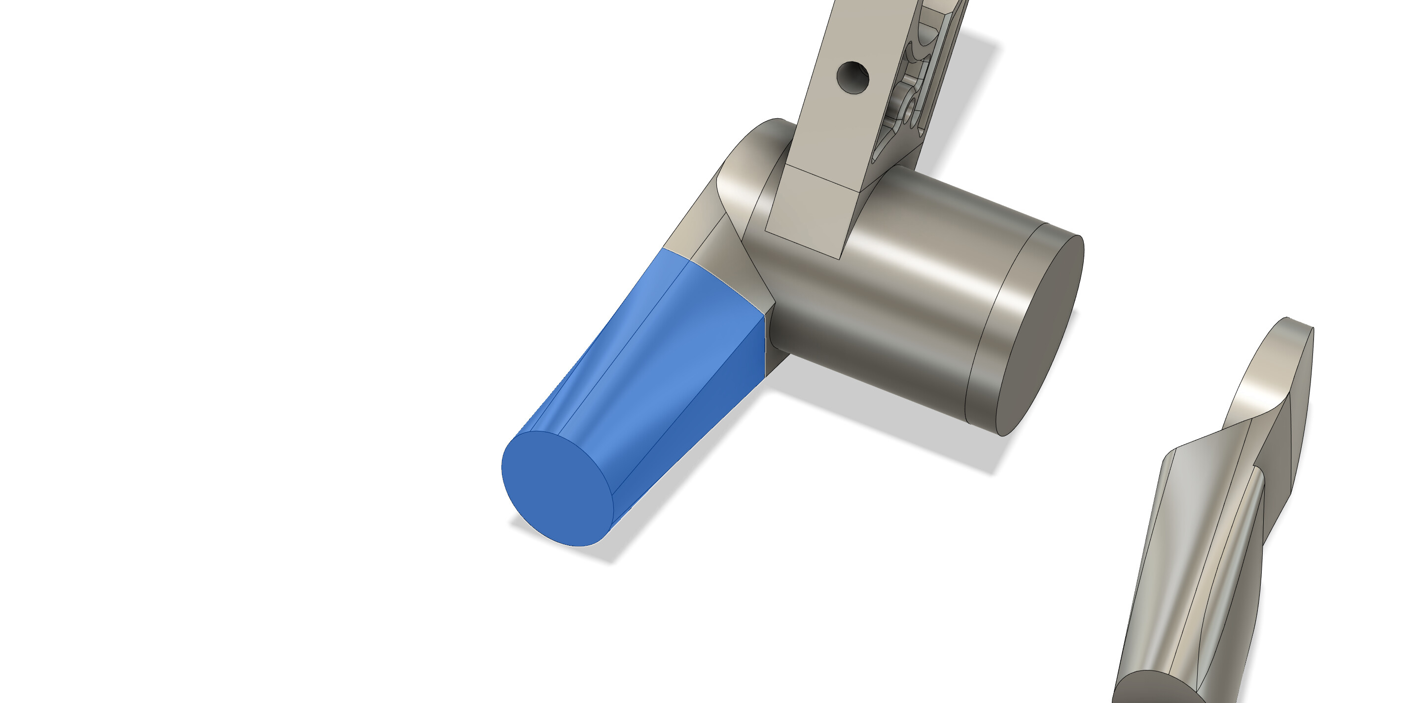
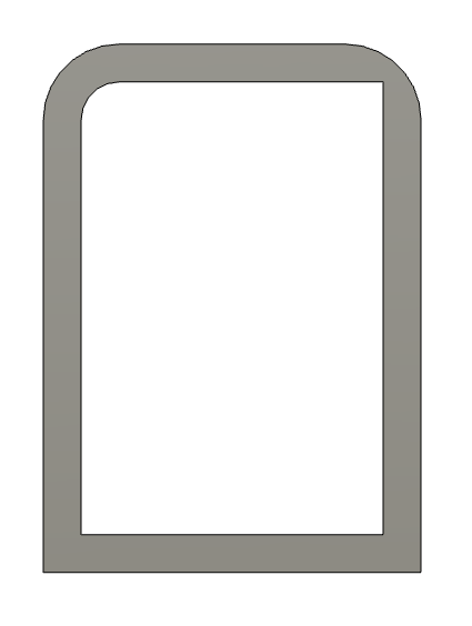
Example of the shape I am currently trying to shell: (only the blue part)
I’m not a Fusion360 user, but I have the same problem every now and then in SolidWorks.
The most common error is when the structure I’m trying to shell has fillets or curvature that would be eliminated or create an ‘inverted’ surface when trying to use the shell command. I tried to make a part and introduce an error so I could give you some screenshots with examples, but of course I couldn’t make it happen…
The workarounds I’ve found to work in SW is to shell before adding fillets, and then manually add fillets to the inside and outside afterwards.
Another solution is to do another loft, using the same shape sketches, but offset by 1 or 1.2mm (whatever wall thickness you want) and then to subract the smaller part.
You can also play around with the variuos tangecy and curvature consistency settings when creating the initial loft that you want to shell.
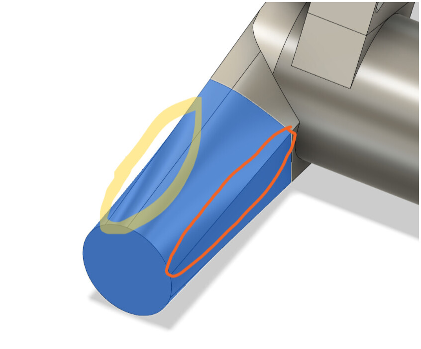
By the looks of it, you have a few surfaces with some uneven curvature as indicated by the shading, and also transitions from a circle to a square and I believe these might be areas where problems may arise.
[Edit]
I was able to trigger an error.
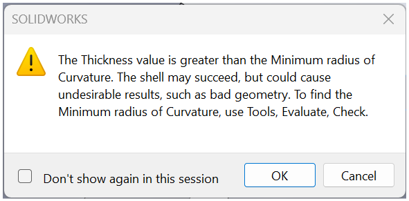
Here’s the message that pops up when the shell command fails (looks like maybe SW gives more info about what has failed).
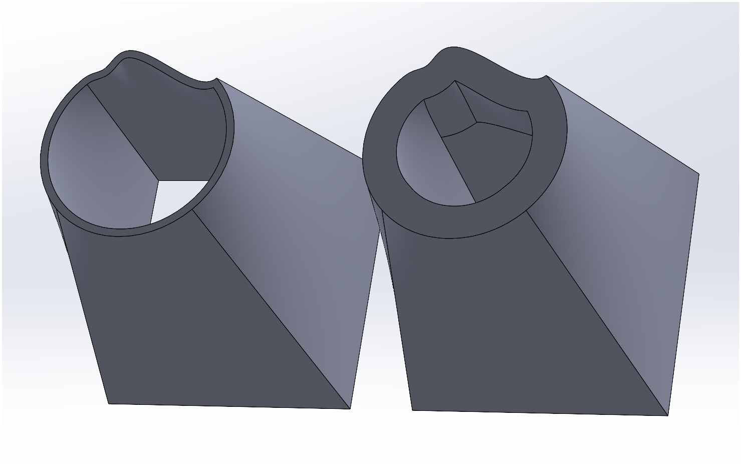
Below is a screenshot of two identical lofted parts. One has been shelled to 1.2mm with no issue, but increasing the thickness to 5mm on the second one made the command break. I could still go ahead and make the shell happen, but as you can see, the inside is not pretty.
I run into this issue all the time, and I think @JMY is correct. I find the error happens when the radii of the fillet is smaller than the wall thickness.
I get around this by adding additional rails and cross sections to my loft to control the geometry. However I think the ultimate solution is surface modeling, because you have more control over the shape.
Thanks for the excellent replies! The fillets were also my first idea. but also without the fillets it doesnt want to fillet. Ive used the making a 1mm bigger loft trick before too, but I figured there has to be a better way to do this. It would be nice if Fusion did the same thing as SW and I can fix the inside of the shell, but alas. This example is pretty simple but Ive had similar problems using rails and multiple profiles, and I havent found a common issue yet.
Time to freshen up my surface modeling skills I guess!
+1 to the other replies here. Frustratingly, some of the issues I’ve had with shelling in Fusion seem arbitrary, i.e. sometimes if shelling a part fails all I need to do is recreate it (using the exact same steps) for it to work. No idea what’s up with that, but now I make sure I shell everything as I go so I don’t sink a bunch of time into a part that isn’t going to work. The zebra analysis tool is useful for highlighting surface areas that don’t have smooth curvature and will present problems to shelling or filleting operations.
I’m sure you’re doing it already, but make sure you add internal fillets if you’re shelling a part before filleting the external edges. You can really thin out the wall thickness if you don’t do this and your printer won’t know the difference. If you want a consistent wall thickness, the radius of the internal fillet is equal to the radius of the external fillet minus the wall thickness.
I get the same error popping up in plain AutoCAD. I suspected disappearing fillets being the error but it also seems random in its error. ie. reopen model and it works. I can’t pin point it down to anything so far.