SolidWork help- Modeling Rear Triangle

My process in SW is assembly based as described above with one significant difference.

I start with a part file that contains all the sketches, axes and reference places to capture all of the geometry and fit information (stem length, fork axle to crown and toe overlap for example). I create a new “configuration” inside this part for each new frame but this is a bit more advanced.

I then create an assembly file and the first part inserted is the geometry/fit file above. Individual tubes are modelled as purchased (or moulded in my case). Theses are then “mated” to the reference geometry in the geometry/fit part insdie this assembly file. From there I edit “in-context” at the assembly level to create the miters required.

As mentioned this allows individual tube and part drawings to be created. By editing the geometry/fit sketch, the assembly model and individual parts and drawing will all automatically update on rebuild of the assembly model.

If you use the configuration method within the geometry/fit part file, one for each frame, you can now quickly flip between individual frame designs inside the assembly with full automatic update of all related files. At one point I had the configurations also swapping between a number of True Temper tubes. It’s a very powerful feature and eliminates a lot of CAD work for each new frame once it’s created.

2 Likes

Can you expand on this?

I am trying this style of design but am stuck on the Top Tube miters. What steps do I need to make the HT and ST cut?

The Down tube was easy because I built the part in the assembly and did an offset extrude up to the BB with a second direction up to the HT. I cannot do that with the TT becasue it is an oval to circle profile so I needed to model it separate.

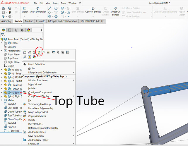
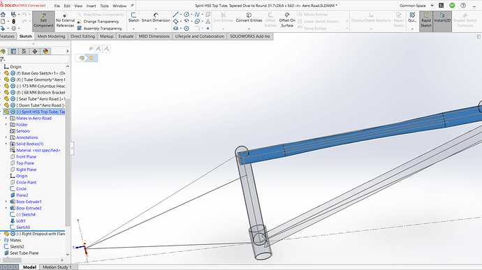
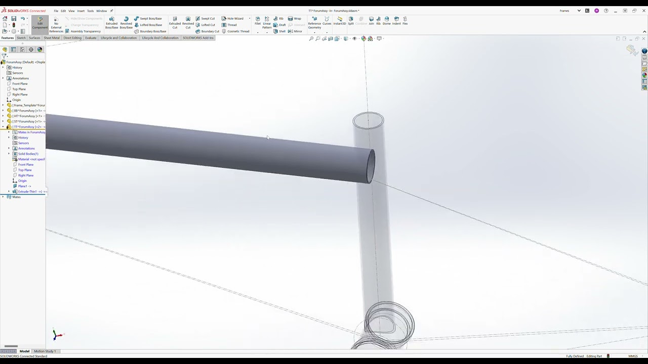
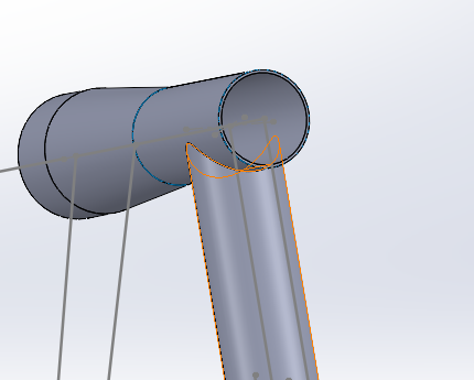
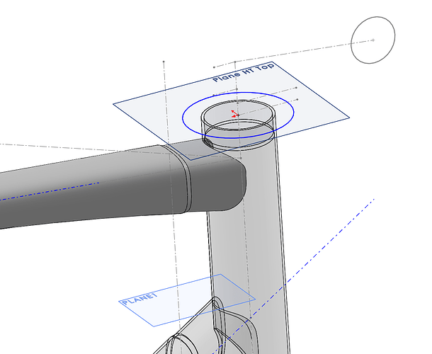
Once you have an assembly file with tubes as parts you can click on a part then “Edit Component”. You are now editing the part within the assembly. You can now add sketches and features to this part while referencing other sketches, reference geometry or parts. In the image below I am editing the top tube in context and using a reference plane to create a sketch (shown in blue). This sketch can then be used to create a cut feature through the top tube. The blue sketch is not dimensioned so you can see it. It should be set as co-radial with the diameter of the head tube (which will fully define the sketch and it will turn black). You can repeat this process for the seat tube miter cut feature.
There are additional steps to ensure you have a stable assembly model. Once you get the hang of editing-in-context I can go over some of these for you.

1 Like

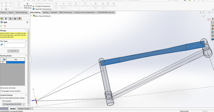
I am trying to learn this because the Extrude Cut would make my miter templates on the ID of the tube. I cannot make Split work in the context of an assembly. I cannot figure out how to make Seat Tube and TT interact for a split

Here at the steps I am trying-
1- “Edit Part”- for the Top Tube

2-Attempt to offset Entities- Greyed out, Is also greyed out if I try when Editing seat tube.

3.If I try to Split, I can only use the TT to make the split which results in the TT being removed. Same if I do the Seat tube.

What am I missing in these steps? I also attempted to make a plane at the top of the ST with a circle for the reference but that did not work either.

NEW INFO FOUND EDIT

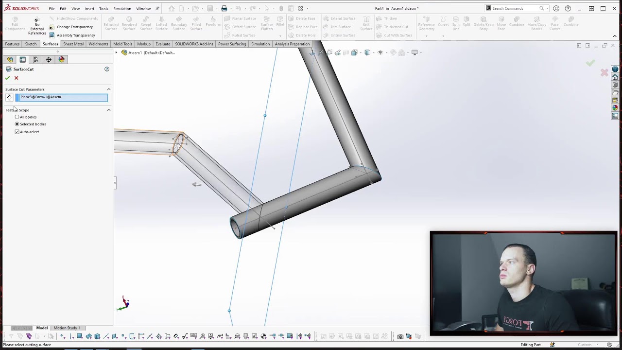
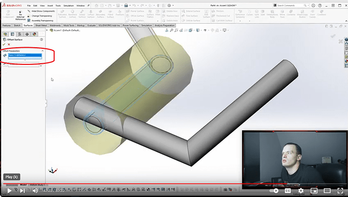
Minute 47:10 of this video is exactly what I need but I am missing the Offset surface selection box.

This is his selection box

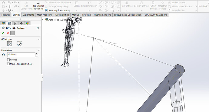
Compare to mine- If I click Offset type, it does not change anything. Also it requires a number greater than zero for offset.

1 Like

Hey Brad,
The command you’re trying to use is “Offset on Surface” which is a sketch command. Check this video here for an explanation of that particular command: https://www.youtube.com/watch?v=fIxBbTII7Gw

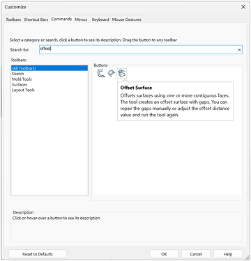
Heaps of useful commands are not part of the standard tool palette, so you may have to enable the Offset Surface command in your toolbar like this:

Right-click in the toolbar, select “customize”, select the “commands” tab and type in “offset” in the search bar. As you see, there are three types of offset commands available. Hover the mouse over each to get a brief description of what the command does.
Drag the command button into the toolbar. Being that this is a surfacing command, I’d suggest dragging it into the surfaces tab of your toolbar.

I’ve spent a lot of time going through commands and figuring out what each can do and I’m still picking up on new things or re-learning stuff I’ve forgotten.

Here’s a video showing two methods to miter the TT to the ST and then the HT.

For simple straight cuts you can draw a sketch on a plane perpendicular to the cut you want to make. In this case, I use the top of the seat tube for the sketch, and I convert the outer edge of the tube. That way if you change the diameter of the seat tube later, the cut will also change along with the tube.

For more complex cuts, that’s when the offset surface & split method comes in handy. As you can see, the HT in the video is not straight, so a straight cut would not give an accurate miter.
So, here I select the “offset surface” command, select the surfaces of the body I want to miter to, then set the distance to zero and accept the command. Then I select the newly created surface and use the split command to select which part of the tube to cut away. In the split command I also enable the option to “consume cut bodies”. That way the cut piece is deleted. Otherrwise it would remain as a separate solid body.
Now that you’ve used the surface for the cut, you can delete the surface body. Or you can hide it in case you think you’ll need to use it later in the process.

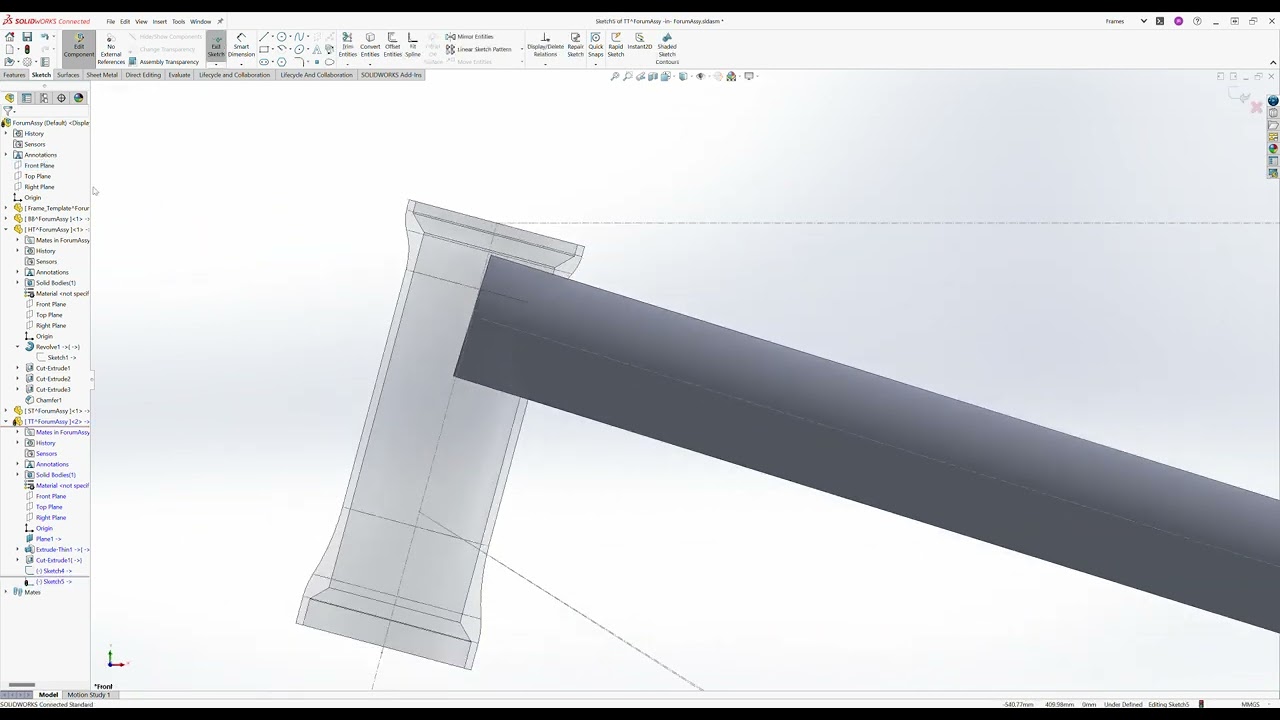
Another way you could trim the TT to the HT in this case would be to create a “revolved cut”.
In the following clip I simply re-use the revolve sketch I used to create the HT shape to begin with by creating a new sketch on the front plane (while editing the TT) and then converting the original sketch for the revolve feature. I then hit “revolved cut” and select the centerline as the axis of revolution.
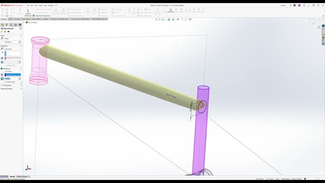
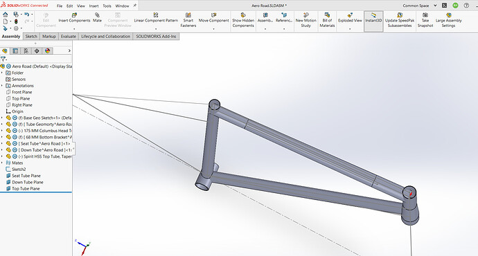
Another way, if you’re creating a straight tube inside the assembly, is to use the “boss extrude” command and set the body you want the tube to butt up against as the terminating body.
To make it work in both directions, you’ll have to set the “from” parameter to be offset from the surface you create the sketch on.
As you can see in my example, the ST has a smaller diameter than the TT, so it will not successfully terminate the feature. My workaround here is to add a 1 degree draft to the second direction of the feature.
Once the extrude has been created, I can go in and shell the tube to whatever wall thickness I want.

[Edit: Looks like linking to videos in my Dropbox, even if set to public, will not work so I’ve changed the video links to YouTube instead.]
2 Likes

I cannot thank you enough! The Split feature with the correct Offset Surface command is doing exactly what I need.

I am over 30 Hours in this project, not much to show on paper but I have learned more SW than ever!

image

3 Likes

Now that I have the front triangle figured out, onto the hard part.

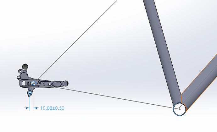
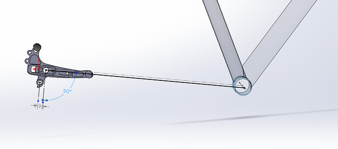
I do not understand how these dropouts work with SRAM specs. In the screenshot below the dropout is tilted as far down as possible while edging up to the 10MM specification.

This is clearly not how others build with this dropout. What am I missing?

Awesome! Glad you worked it out!

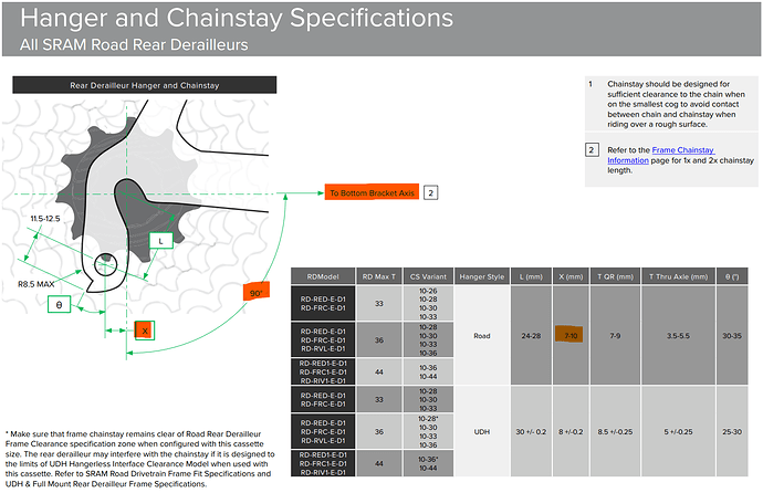
The 10mm measurement should be perpendicular to the BB to axle centerline, not horizontal.
The illustration below shows a frame with no BB drop (which is a bit unrealistic).

Here’s a link to the latest SRAM frame fit specs where the screenshot is grabbed from.

2 Likes

That is what I was missing! This looks much better.

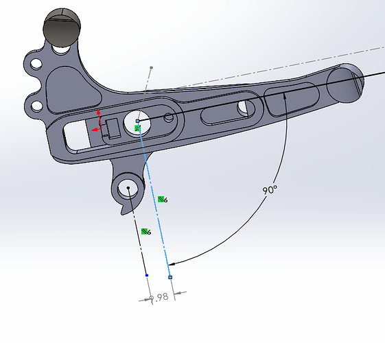
Any recommendations on how to Dimension this better? I made a Plane on the surface of the dropout, Made a line for BB to axle, another line at 90 degrees from CS line, and one parallel to that.

I would like to be able to change the angle of the drop out and watch the Axle to hanger distance change. If I rotate the dropout in this situation, the CS line moves with it leaving the BB axis.


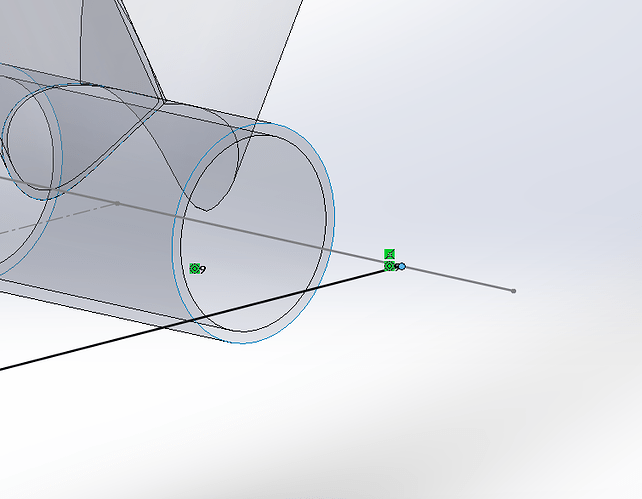
Are you using “Convert Entities” that may allow you to project the BB center location, causing the virtual CS to be locked with the BB.

Also, the hanger spec is a murky space (it should not be). SRAM and Shimano have different specs. MTB and ROAD hangers have different specs… I don’t even think most specs are up to date with 2023 derailleurs!

The best you can do is look for the specification of the derailleur you are planning to use.

Also, great job learning Solidworks. It is really impressive to see your progress.

1 Like

I don’t know exactly what’s going on, but I think you may have constrained the sketch to the dropout.
It looks like you’re in “edit part” mode, so even though the CS line is set to be connected to the BB centerline, the sketch is locked to the dropout part.
What you may need to do is to create the same sketch in the assembly itself. The sketch will retain its relations to the various parts of the assembly and update as you change the angle of the dropout.

I’m assuming you’ve made a concentric mate around the axle bore and the axle centerline sketch?

Very true.
Look also at the overlap between the SRAM Road and UDH hanger spec.
The only configuration that won’t work across both hanger specs is a 10-26t cassette using a max 33t derailleur on UDH.

2 Likes

This is what I needed. I made that plane in the dropout assembly therefore it always would move with the dropout. I would have never guessed modeling a bike would be harder than making one :rofl: Thanks!

1 Like

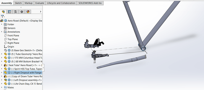
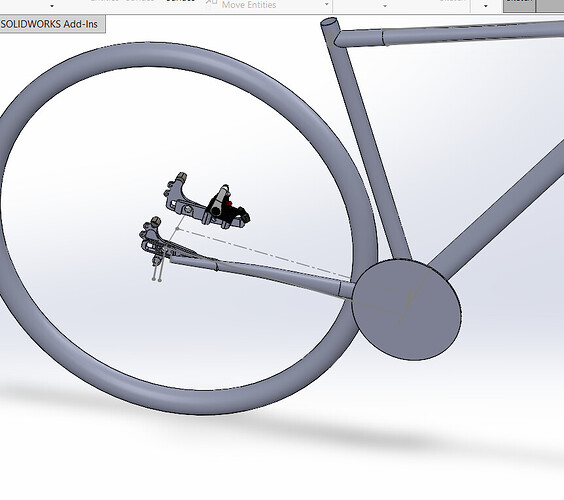
I think I am at the point that I can use your input. I have a front triangle made of all individual parts and I have located and indexed my rear dropouts. I made the Chain stay I want to use (I am very proud to have figured out a tapered curved tube).

How do you constrain the chain stay to the BB and dropout?

1 Like

There are different ways to go about this, but one way that I find useful is creating planes and axes in your part that you can match up to your assembly. For example, create an axis in your chainstay part that is roughly where you want the axle to go and then a plane that you want to be your center plane. Once you mate the chainstay in your assembly, you can adjust the axis and or plane in the chainstay model to bring things into where you want them.

Well done!

I’m assuming you have a centerline that defines the curve in the chainstay?
And you will probably also have a plane in the chainstay that the centerline is sketched on?

If so, use that plane and constrain it to your CS plane (if you’ve created one). This will mean that the CS component only has 2 degrees of freedom - forward/backward, and left/right. Edit the centerline sketch and place a sketch point on it. You can then define how far you want that point from the endpoint of the centerline sketch. Ensure the centerline sketch is unhidden and use the newly placed sketch point and constrain that to the centerline through the BB.
You can then use a distance mate from the outside face of the BB to define how far from the edge the CS should be on the BB.

Use a similar approach to constrain the other end of the CS to the dropout.

2 Likes

That worked, thanks!

It is amazing to see chain ring/tire clearance. Thankfully I am finding chain stay to dropout issues now due to the length of these dropouts. This is proving to be worthwhile work!

4 Likes

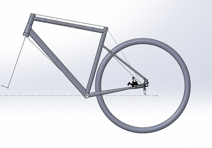
Thank you all for the help!!! I finally have the model done. This has been a huge learning experience, not bad for my first SW assembly. Trial by fire for sure!

Its hard to see but the Top Tube is Oval/Oval and the Down Tube is an aero teardrop. The next step is figuring out miter templates. I will be very excited to have a miter template for a tapered HT to Areo DT.

4 Likes

Looks great! Well done!
Miter templates in SW are a bit tricky. Unfortunately, the only way I know how to do it requires the Professional or Ultimate versions to allow the “flatten surface” command.

But, there’s a nifty way around it. Open a file that’s been created in a version that includes the flatten command and has the command used in the feature tree. You can then roll back the feature tree, place what you need to flatten before the flatten command, then edit the flatten command to run on your geometry.

Search the SolidWorks user forums for: “Seed File for Surface Flatten”.
You’ll be able to find both the seed file and an explanation for how to use it.

4 Likes