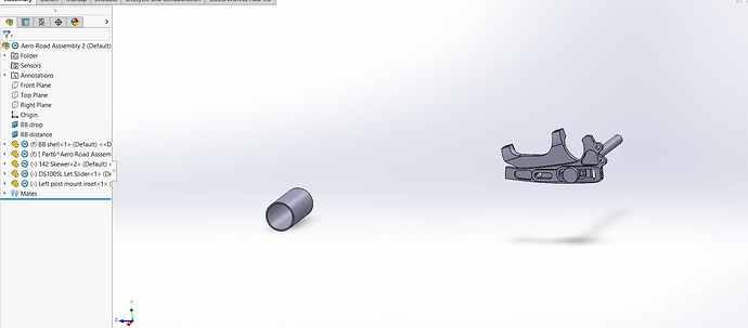
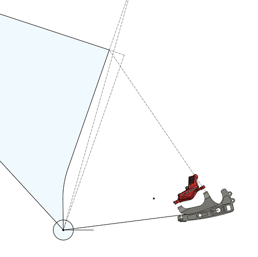
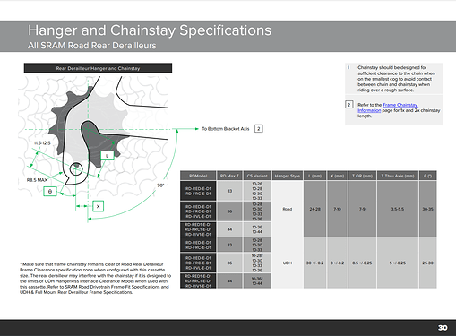
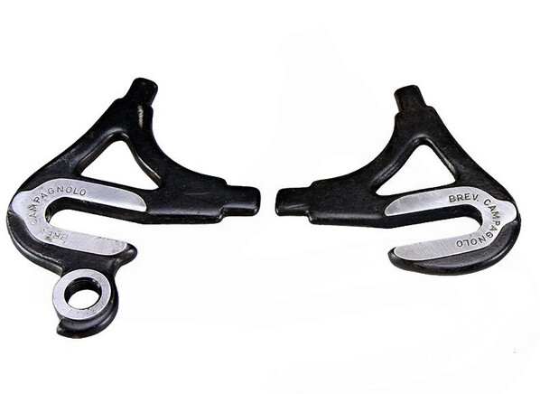
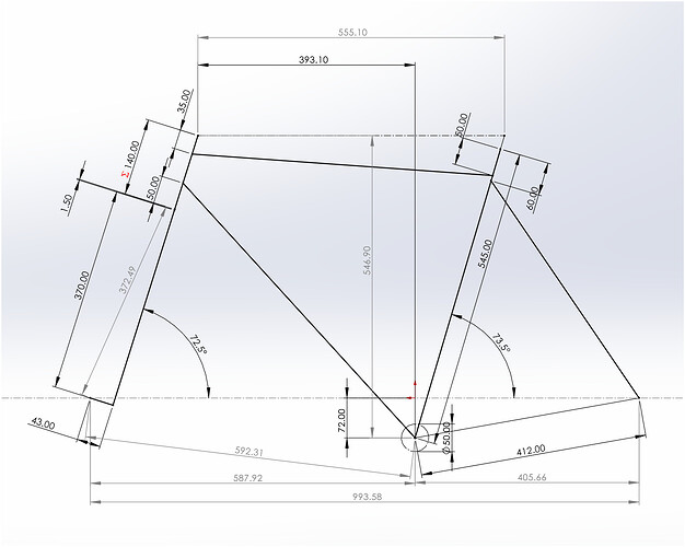
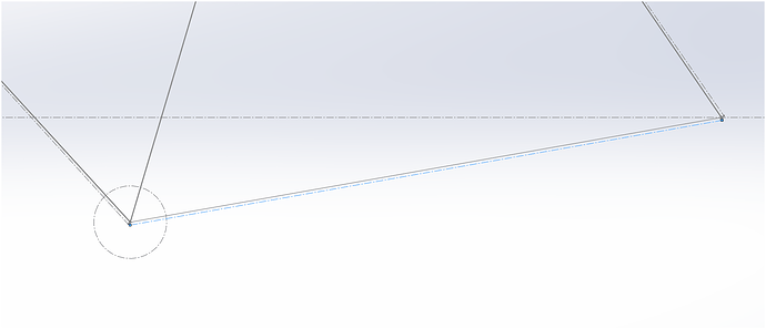
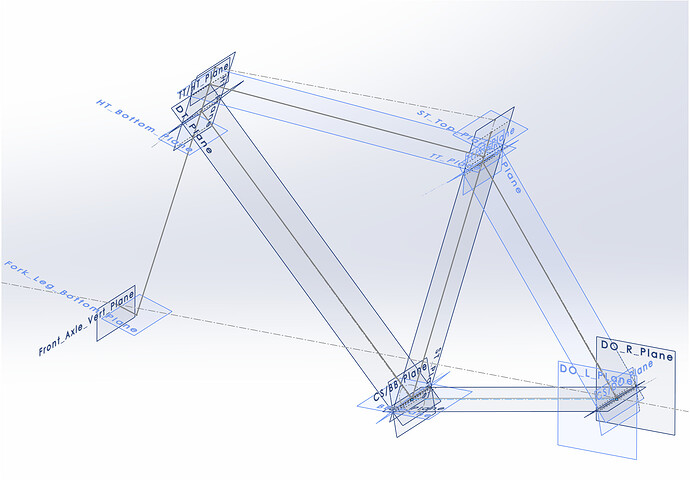
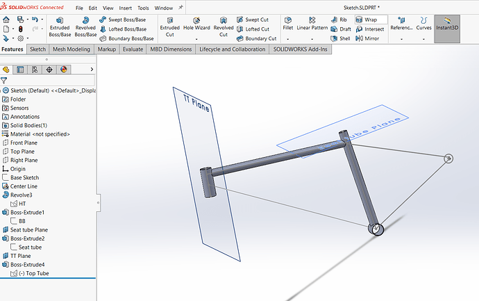
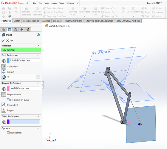
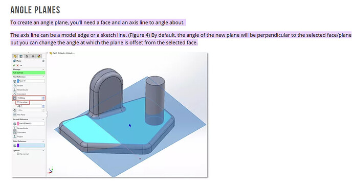
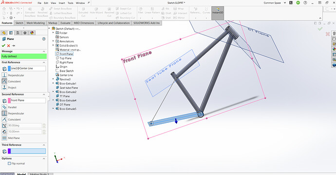
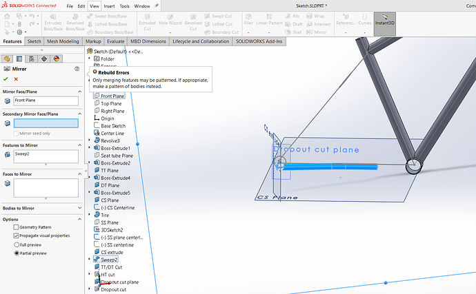
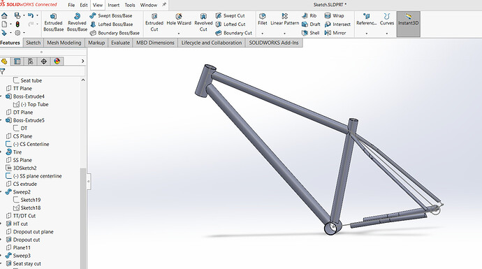
You’re definitely making progress and you’ve figured out the plane creation. As you’ve noticed, you have to assign a second reference to create a plane from a sketch line. A plane needs at least 2 references to be fully defined, unless you’re creating a parallel offset plane from an existing plane or surface.
As for trimming geometry, tubes for example, here’s where SW and Fusion diverge a bit. As Daniel mentioned earlier, the CAD packages all have the same basic functionality more or less, but the buttons and function names may differ.
In SW the feature you want to use is not called “Combine” - the most similar function is called “Split”.
I haven’t worked at all in Fusion so I’m not sure how it works there, but in SW you have to differentiate between modeling as a part, or in an assembly.
When modeling in a part file, whenever you make solid geometry that intersects, the geometry will merge by default, creating a single solid body. If this is not what you want, you have to manually uncheck the box “Merge result” in the tool sidebar so you end up with separate solid bodies that you can edit separately. These bodies can later be merged if you so wish.
If you’re instead modeling as an assembly, all the parts will remain separate and you can not merge them into one solid. In order to, for example, trim a down tube to create a miter to say a BB shell, you will have to first either import or create the geometry. You know how to do this already.
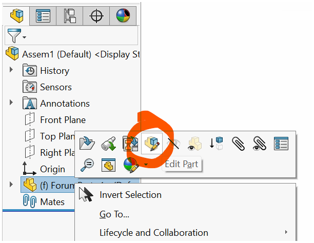
To create the cut in the DT you will have to right click on the part in the feature tree and select “Edit part”. This will allow you to edit that part on the part level, but in the context of the assembly.
There will be a couple of ways to achieve the cut. You could for example create a sketch on the BB face and do a simple extruded cut (through all, or up to next), or you can make the sketch on the front plane and do the extruded cut with the option “through all - both” selected. Another way would be to offset the surface of the BB shell using the “offset surface” tool, set the offset distance to zero, which will mean that the surface is copied rather than offset.
Then you use that copied surface to split the down tube and during the split operation you can assign which part of the down tube is “consumed” during the split.
Note that after this operation, your part file for the down tube will contain one surface body (the offset BB surface) and a solid body (the remaining part of the DT).
The surface split option is handy if you want to trim geometry to a more complex shape, such as a tapered head tube for example. But if it’s just a straight cut you’re probably better off just going for a simple extruded cut.
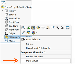
One thing to note is that if you’re modeling in an assembly and you edit an imported part file, that part file itself will be modified. The modification does not just happen at the assembly level. So unless you want the original part to be modified you will have to embed the part file in the assembly by making it virtual. That creates a copy of the part inside the assembly and that part will no longer be linked to the original part.
