We’re in Alpine now. Found a 1917 (supposedly, it may be 1890s) house that needs a little work.
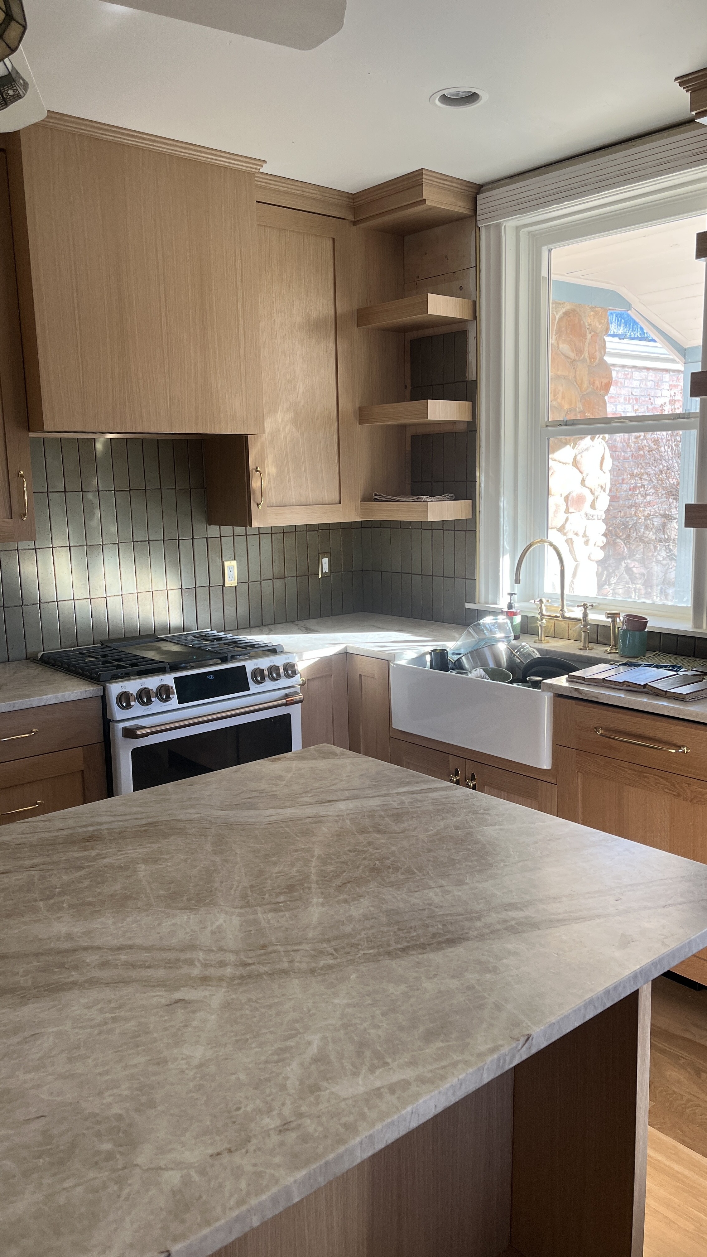
I just finished the backsplash in the kitchen this weekend. Still a lot of projects, but the big ones are done.
We’re in Alpine now. Found a 1917 (supposedly, it may be 1890s) house that needs a little work.
I just finished the backsplash in the kitchen this weekend. Still a lot of projects, but the big ones are done.
Nothing like a house move to get in the way of frame building! Just recovering from that myself!
The water heater of course kicked the bucket and dealing with the home warranty has been . . . fun.
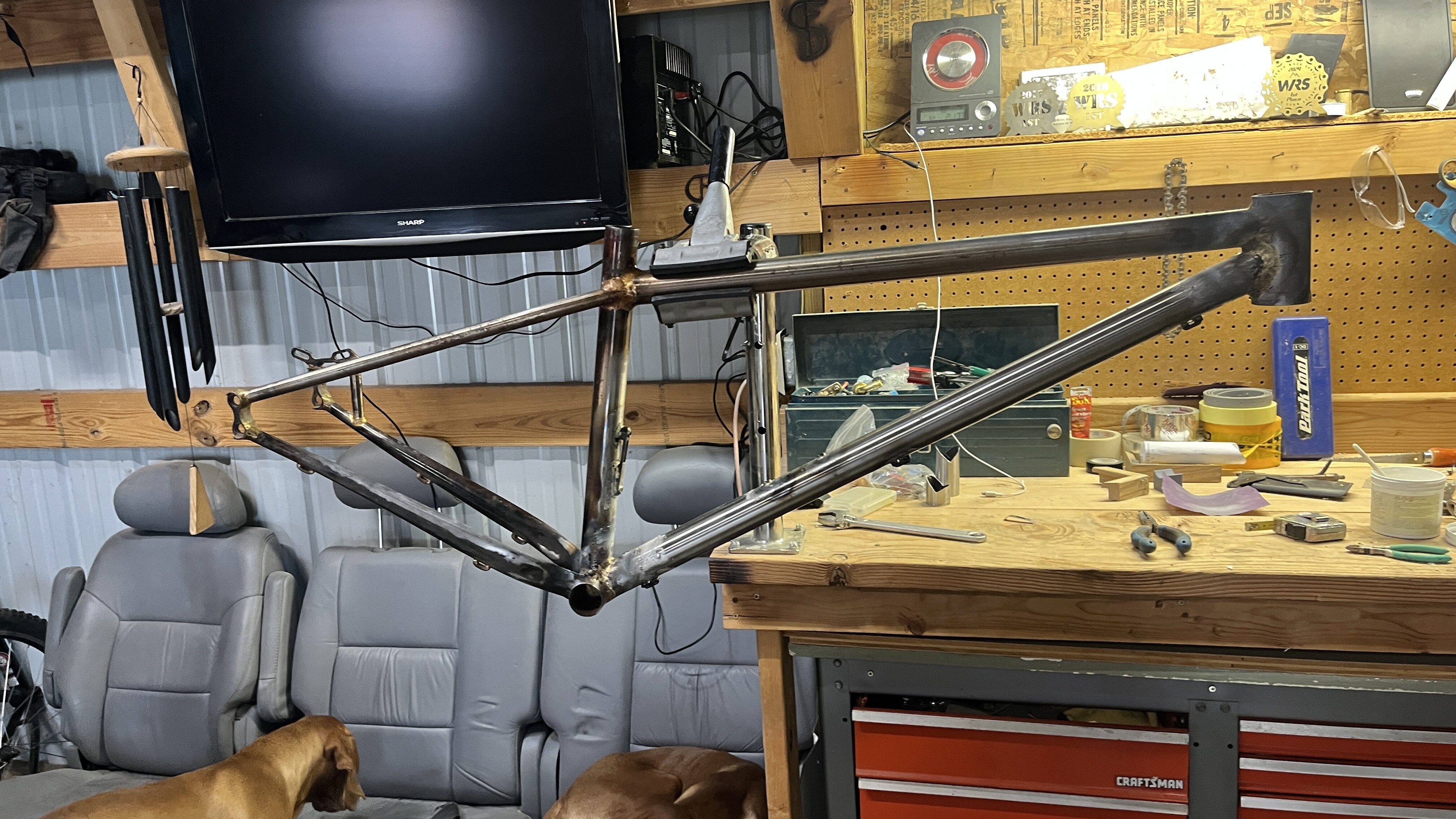
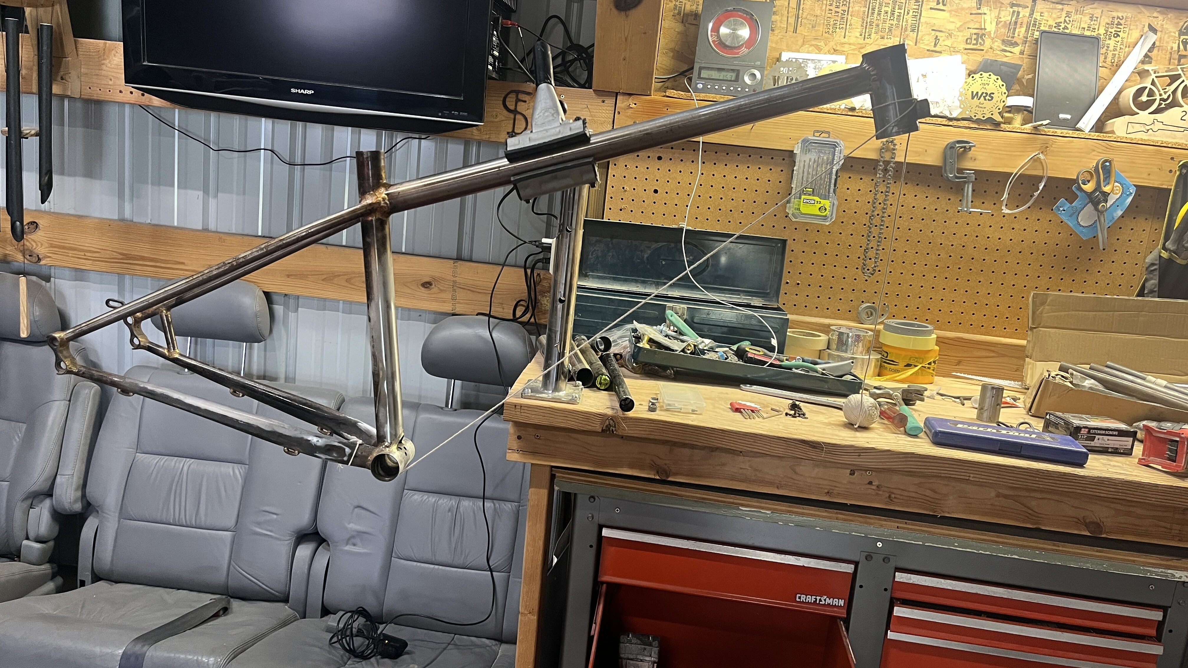
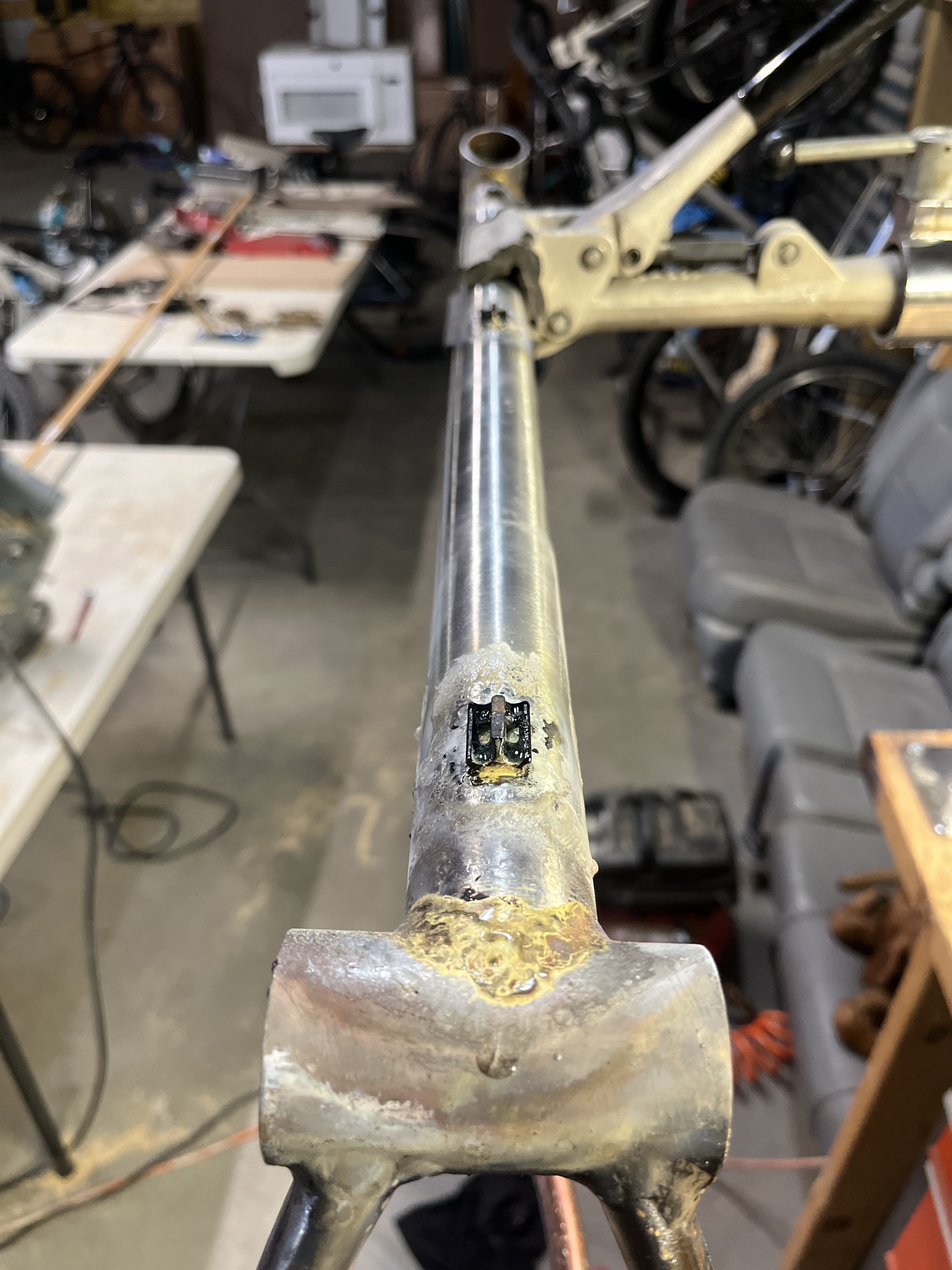
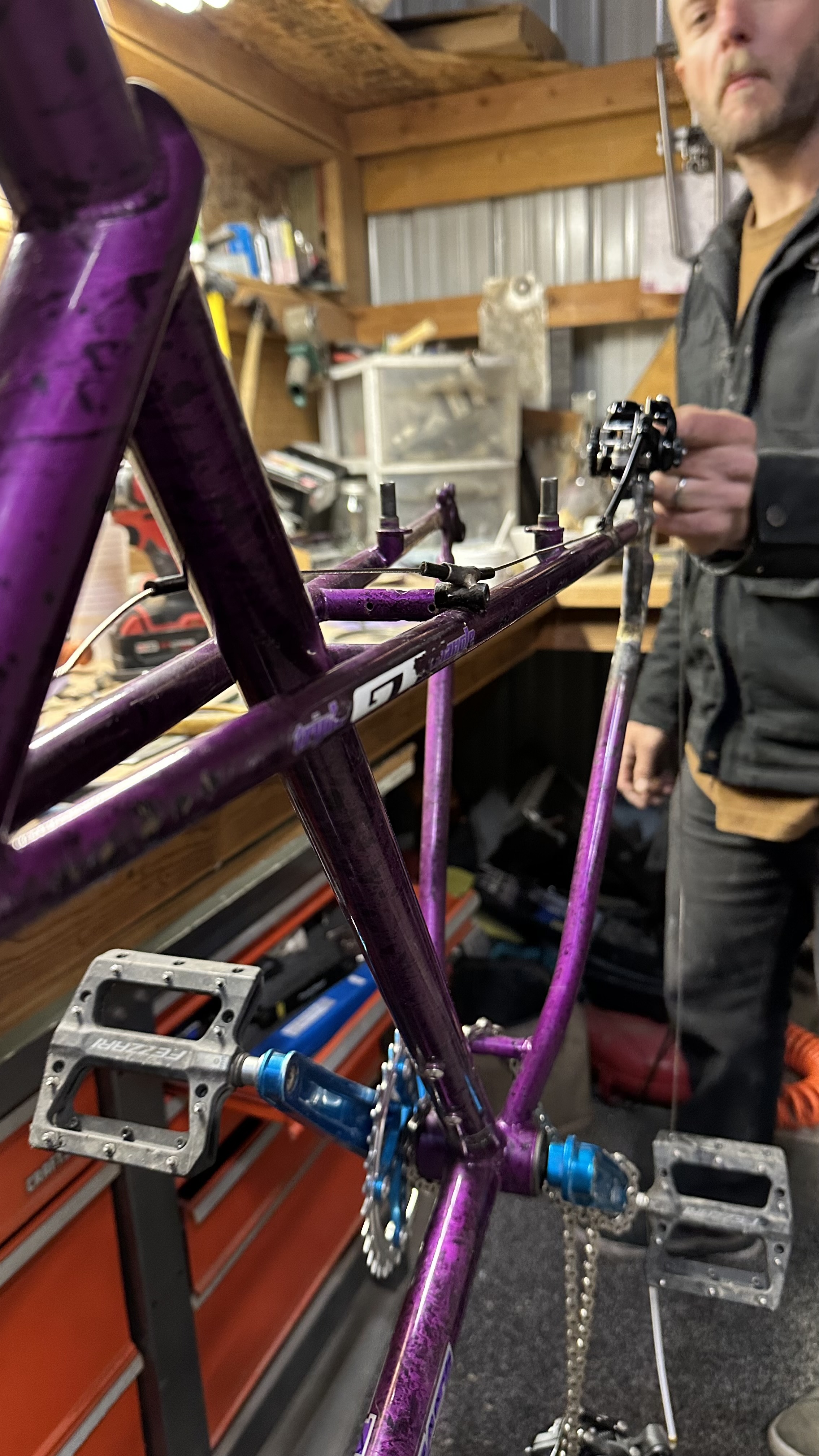
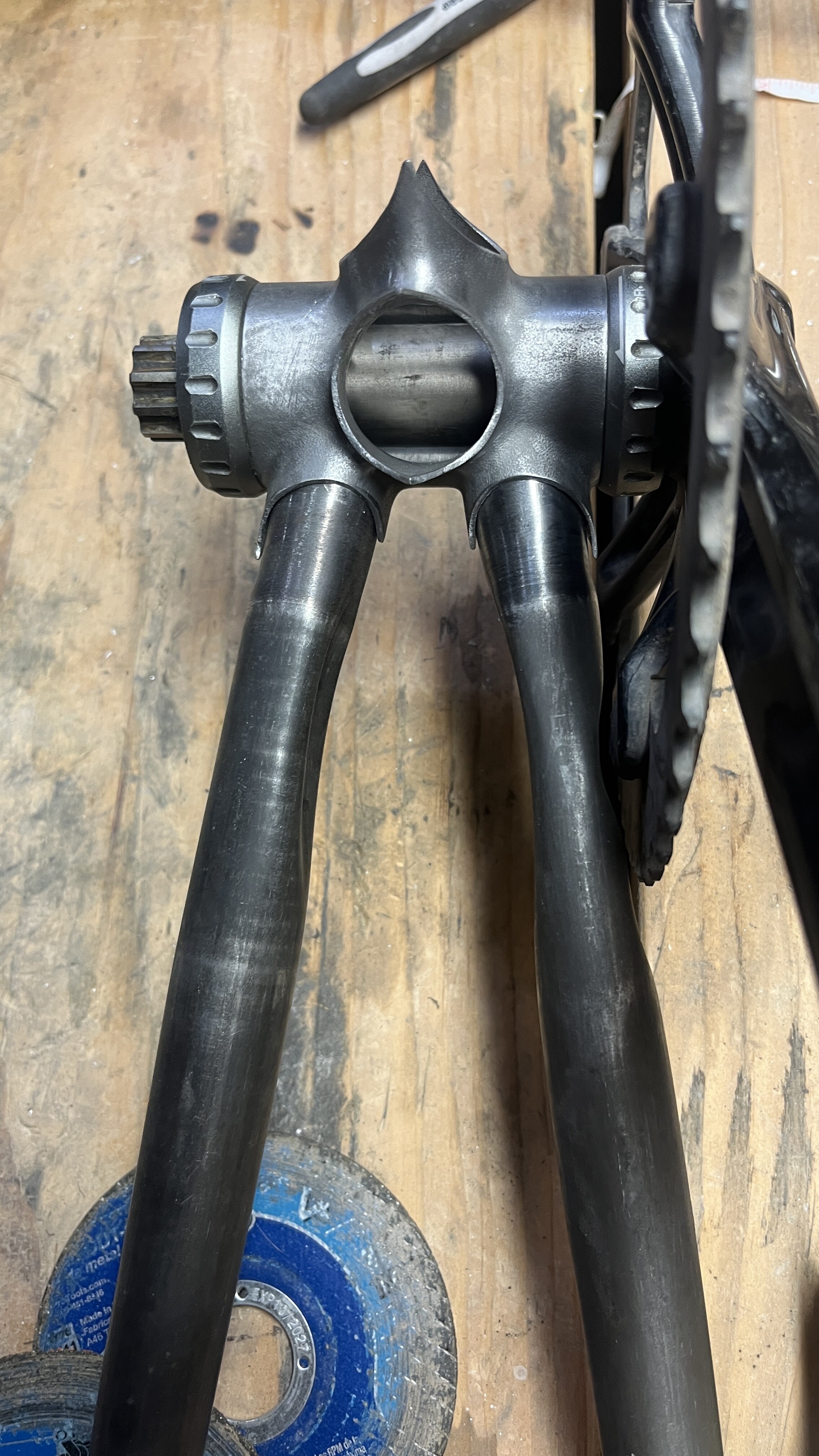
I’ve FINALLY replaced the downtube of my hardtail frame. If you remember This Post in the Fail Thread, I cracked the 34.9mm Downtube up at the head tube junction November 2024. I left it with a friend in June of last year so he could develop and test his “stuck seat post puller”. He broke 3 versions of that before he could get my seat post unstuck. But about a month ago, he told me he got it out. (grease your seat posts kids)
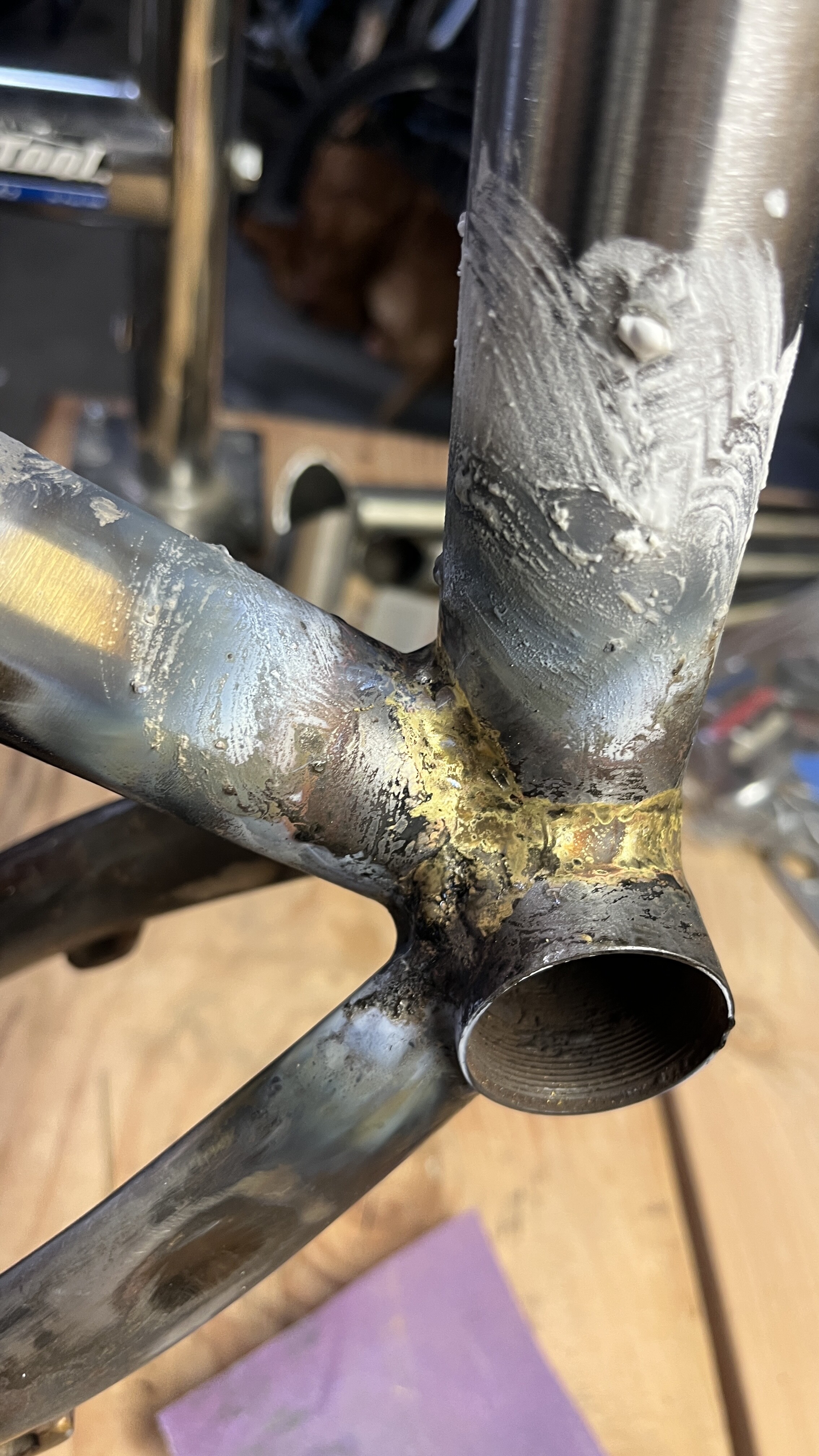
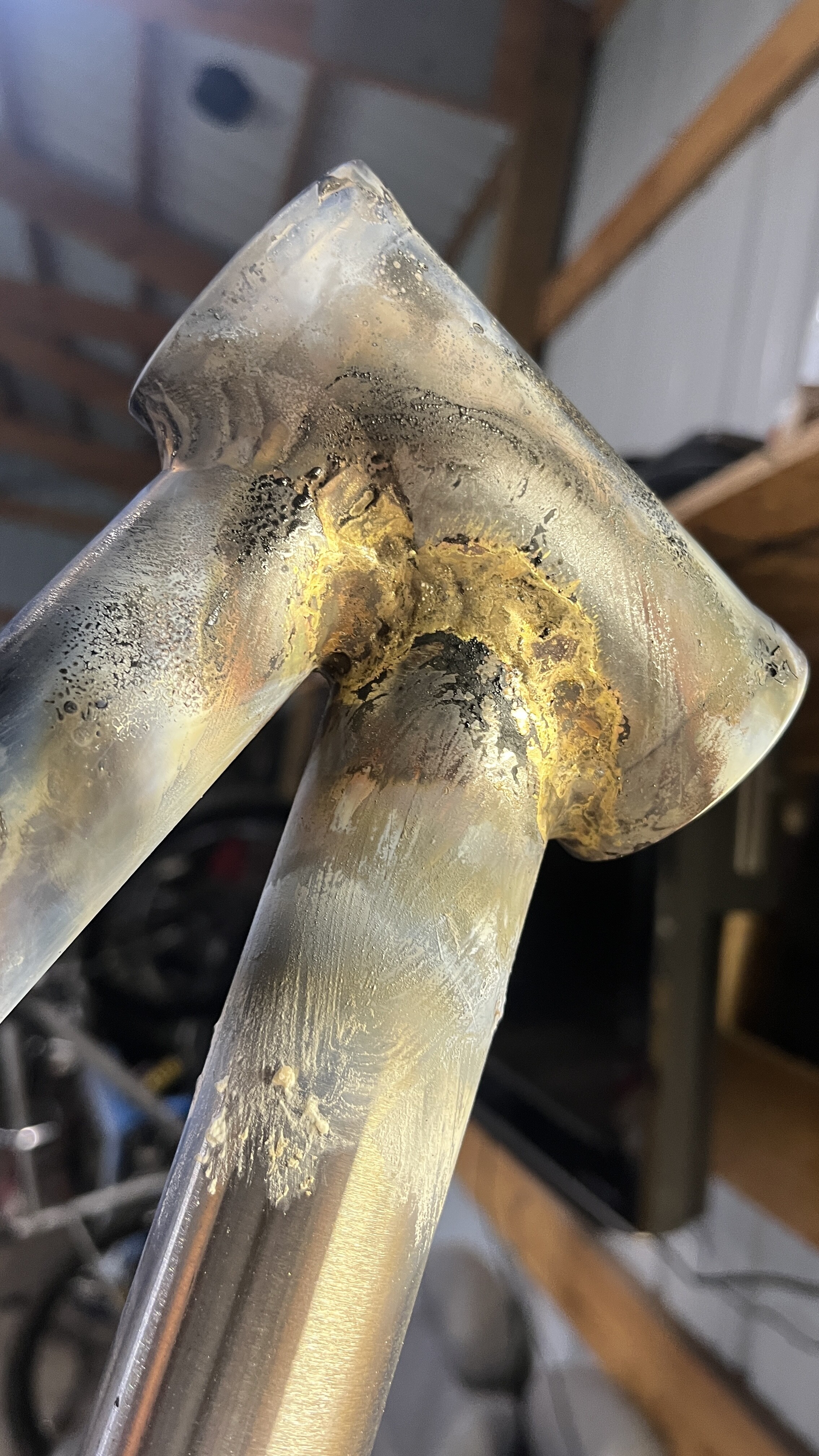
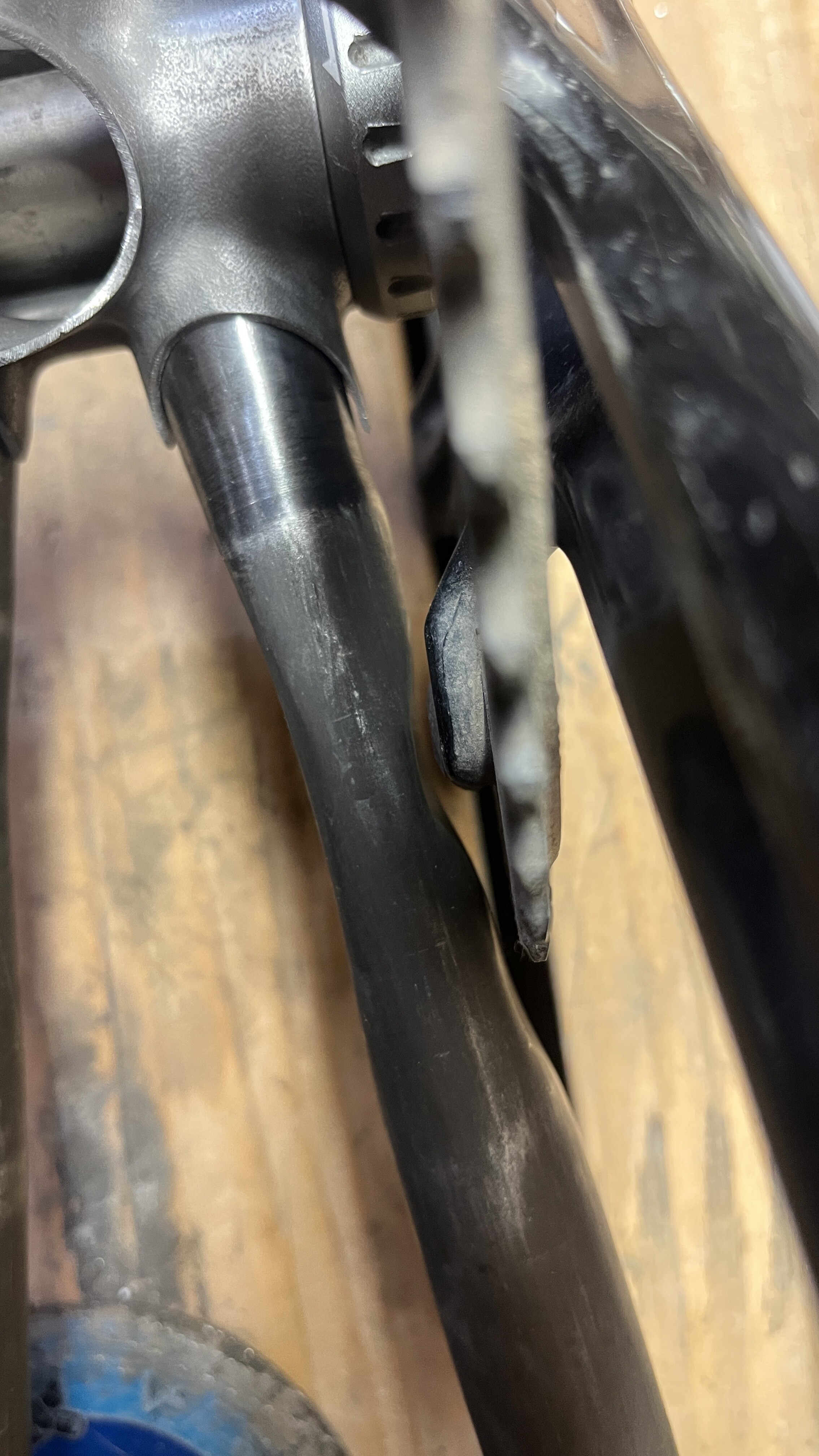
I cut the old downtube out, and sanded and filed back all the old downtube bits and braze. I measured the distance with a string. (the string didn’t really work but the ol’ eyecrometer did the trick) Cut and mitered the new 38.1mm tube and then brazed it in. Wish I had more photos, but I get in the groove and just charge ahead. I think it’s my ADHD hyper focus mode, let me know if you experience similar.
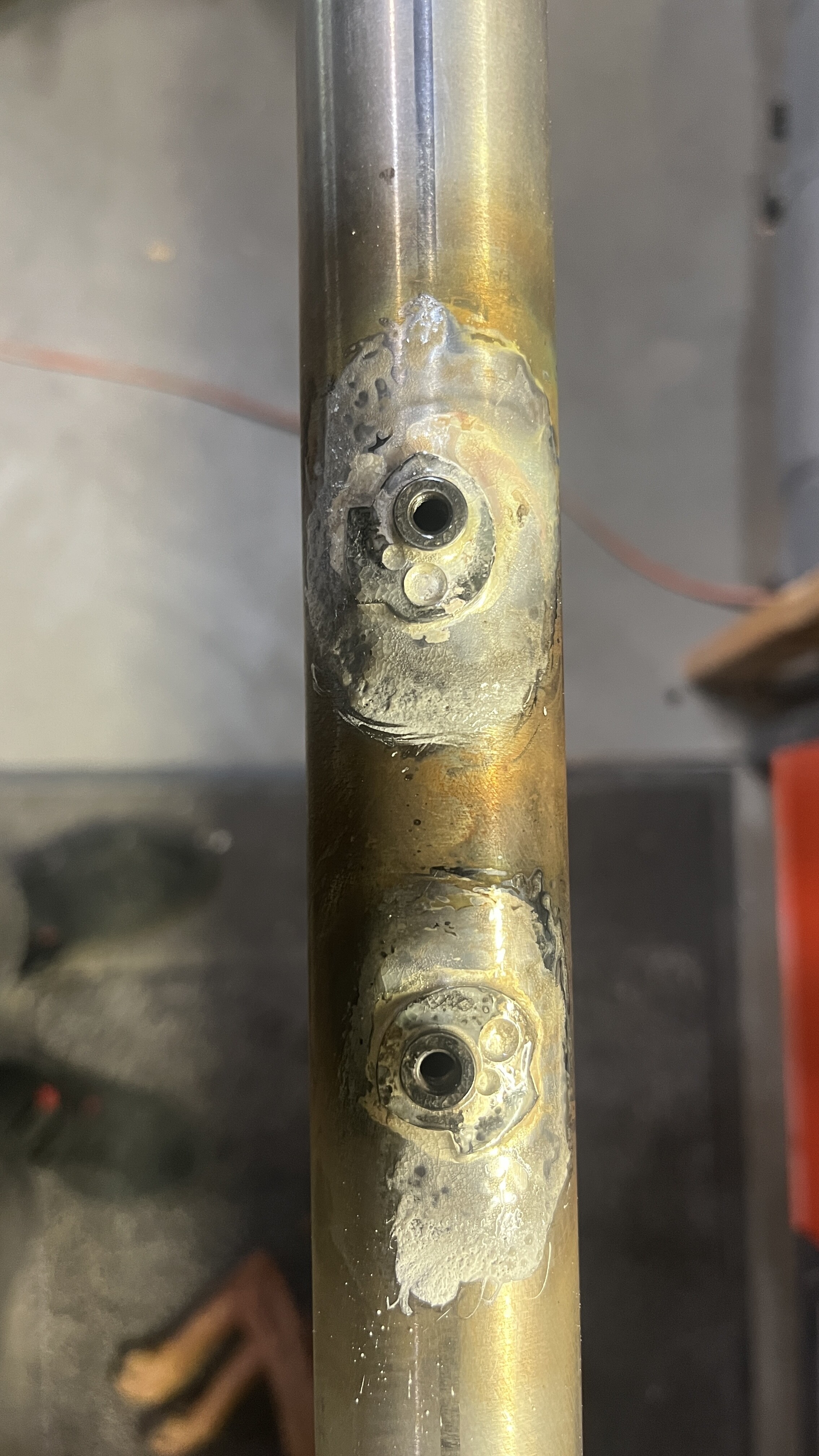
I reused the cable guides from the old downtube after I torched them off. They are quite crispy, but they only have to hold cables, so it doesn’t matter. And my plans for paint are gonna be quite ugly, so nothing really has to be perfect.
Sweet! Which tube did you end up using?
This one. I’ve got a 160f/150r alloy prototype from work that I have to test right now so that’s taking the abuse. This bike will still get ridden hard, but maybe not as hard as before.
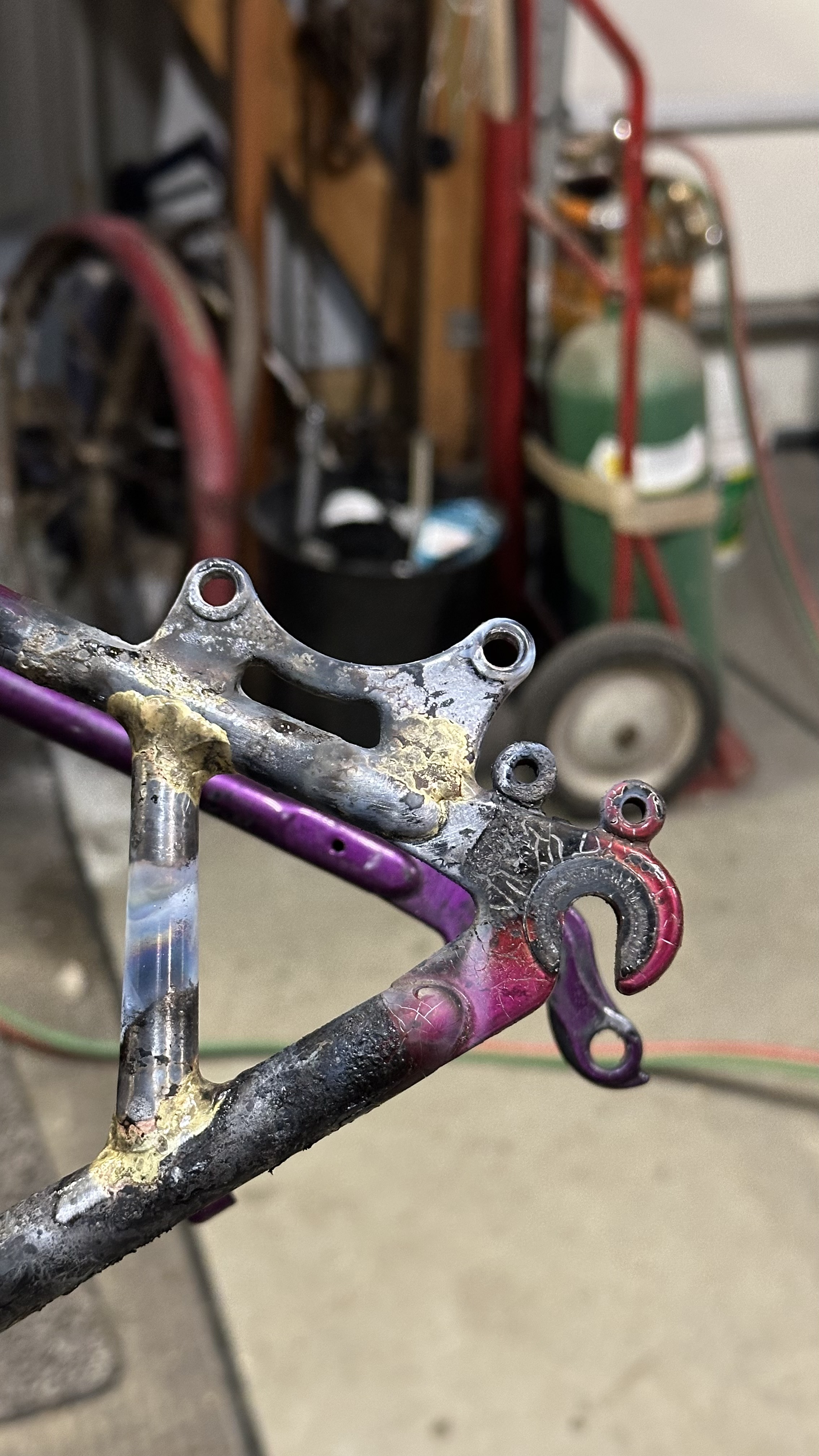
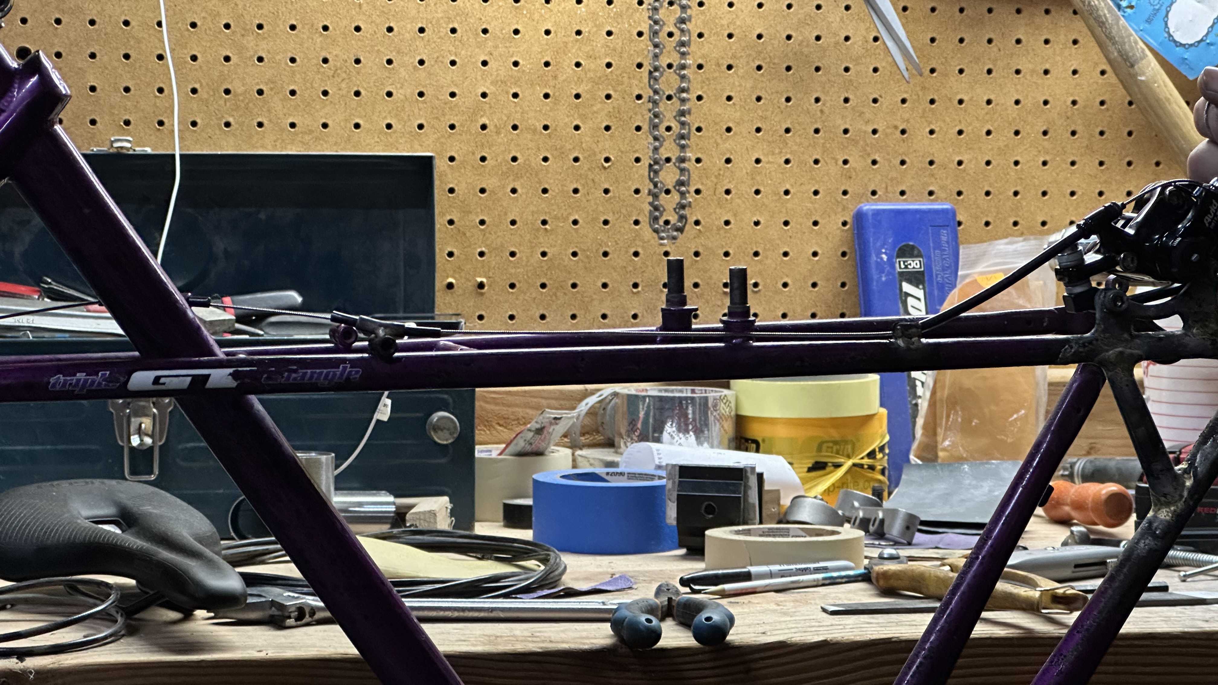
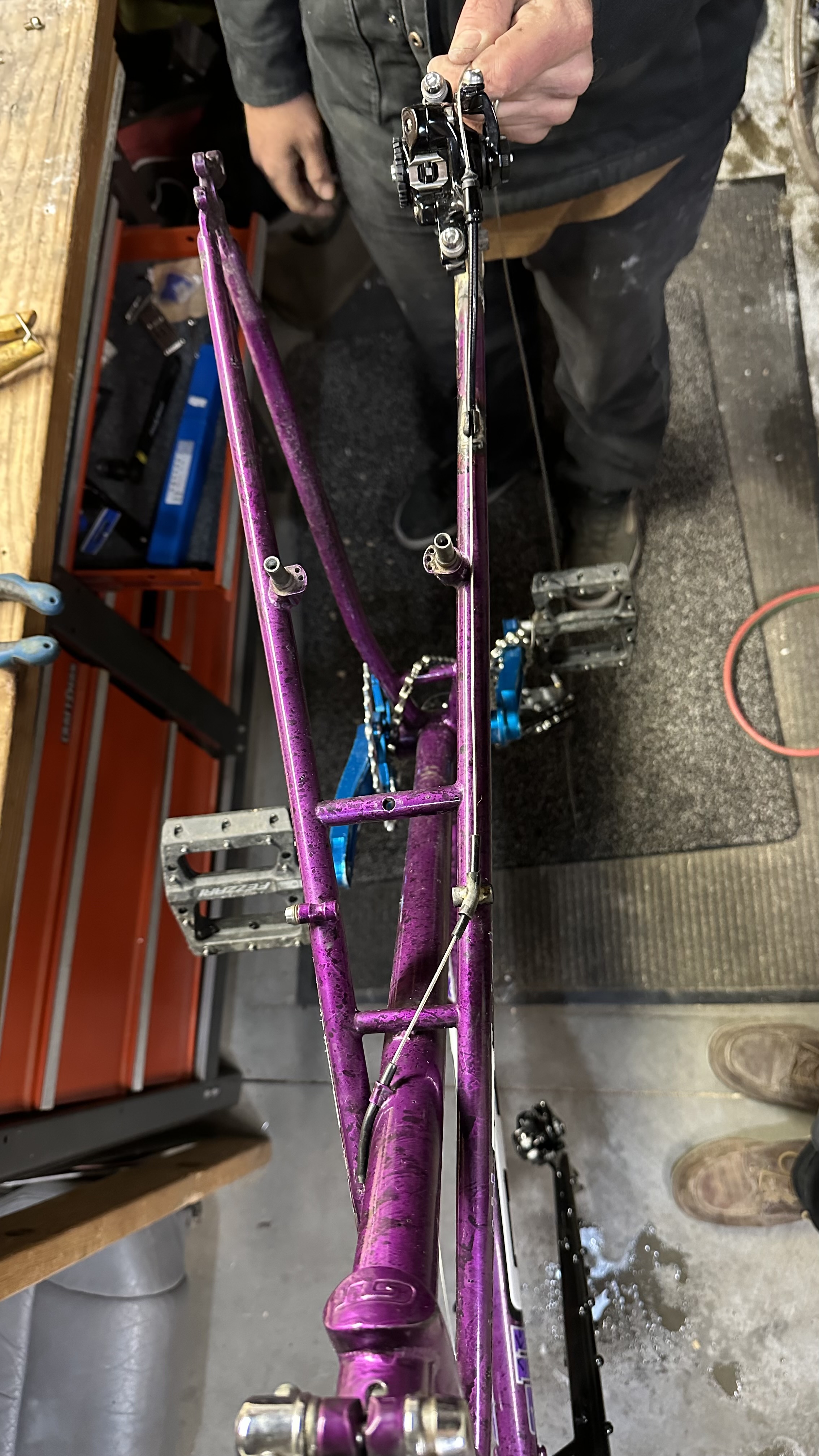
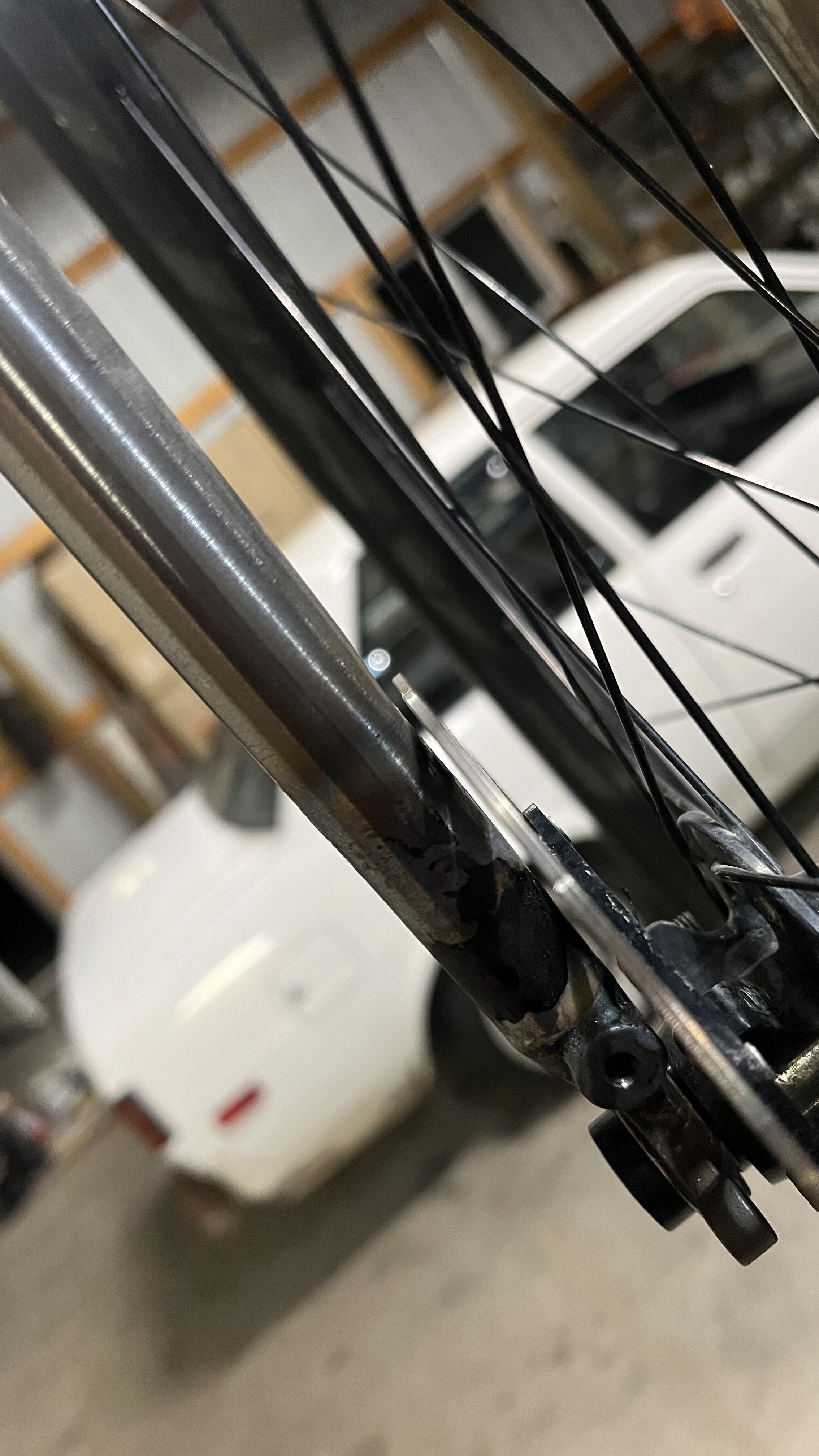
I really want to take some nice photos of my hardtail before I post them up here, so I’m going to post photos of the old school GT frame modification I did with a friend yesterday.
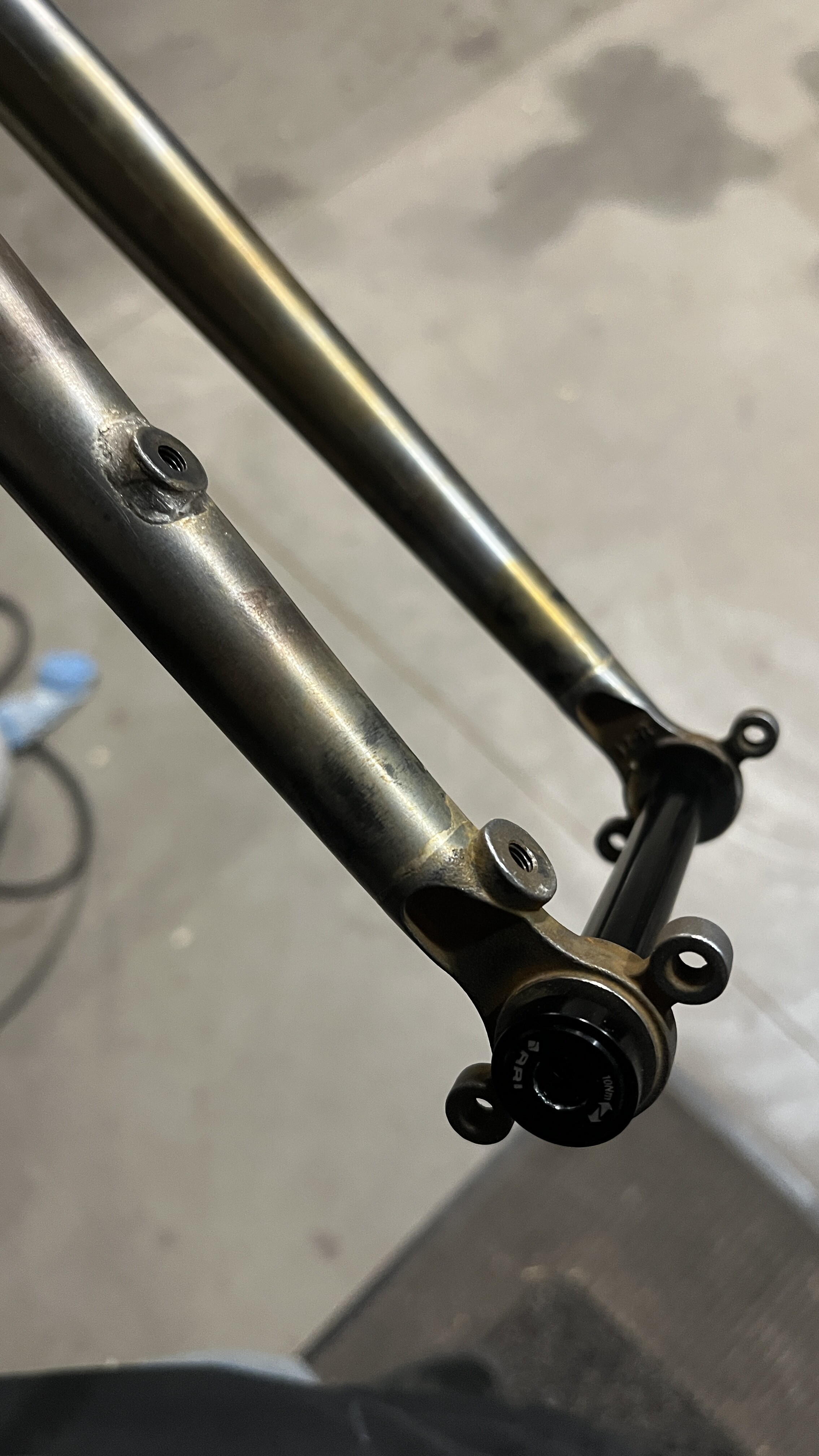
We changed the rear IS mount to the front standard to allow for slightly larger rotor options (not that he’ll use them) and that keeps the mount above the rack mount so we don’t have to cut it off.
I’m trying not to just dump photos here, but I’ve been working on several different things at the same time, so I’ll do my best to manage that.
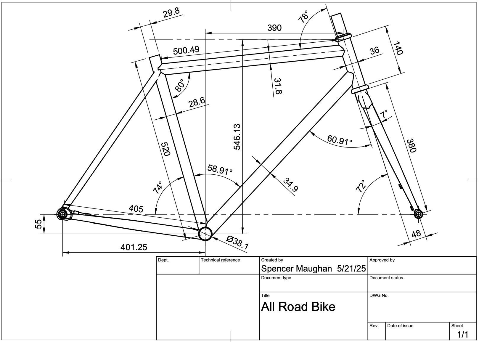
This post will be about the All-Road bike I’m making. I’ve made some decisions and I’m gonna explain my thought process because it makes me laugh. I ride track bikes to work most days. I like the agile nimble quick handling. I was thinking about the all-road category and how my personal version of an all-road bike would be different. I like the tire clearance because I don’t believe tubeless tires below 28mm should even exist. But due to my track bike riding, I don’t like the higher stack that these all-road bikes have. Also, because I commute like a man who has no sense of self preservation, I prefer a higher bottom bracket that allows me to pedal through corners and not worry about pedal strikes. After looking at my design, I realized it was a Cyclocross bike. So that’s what I’m gonna make. I’ll keep the fender mounts, but I will ditch the dynamo routing. (saves some money anyway)
I’ve been slowly making progress. I am planning a lugged frame sometime this year (if I’m lucky) so I thought I would practice my silver brazing. I’m a little rusty, but after some practice I was feeling better.
How much dimpling is too much dimpling?
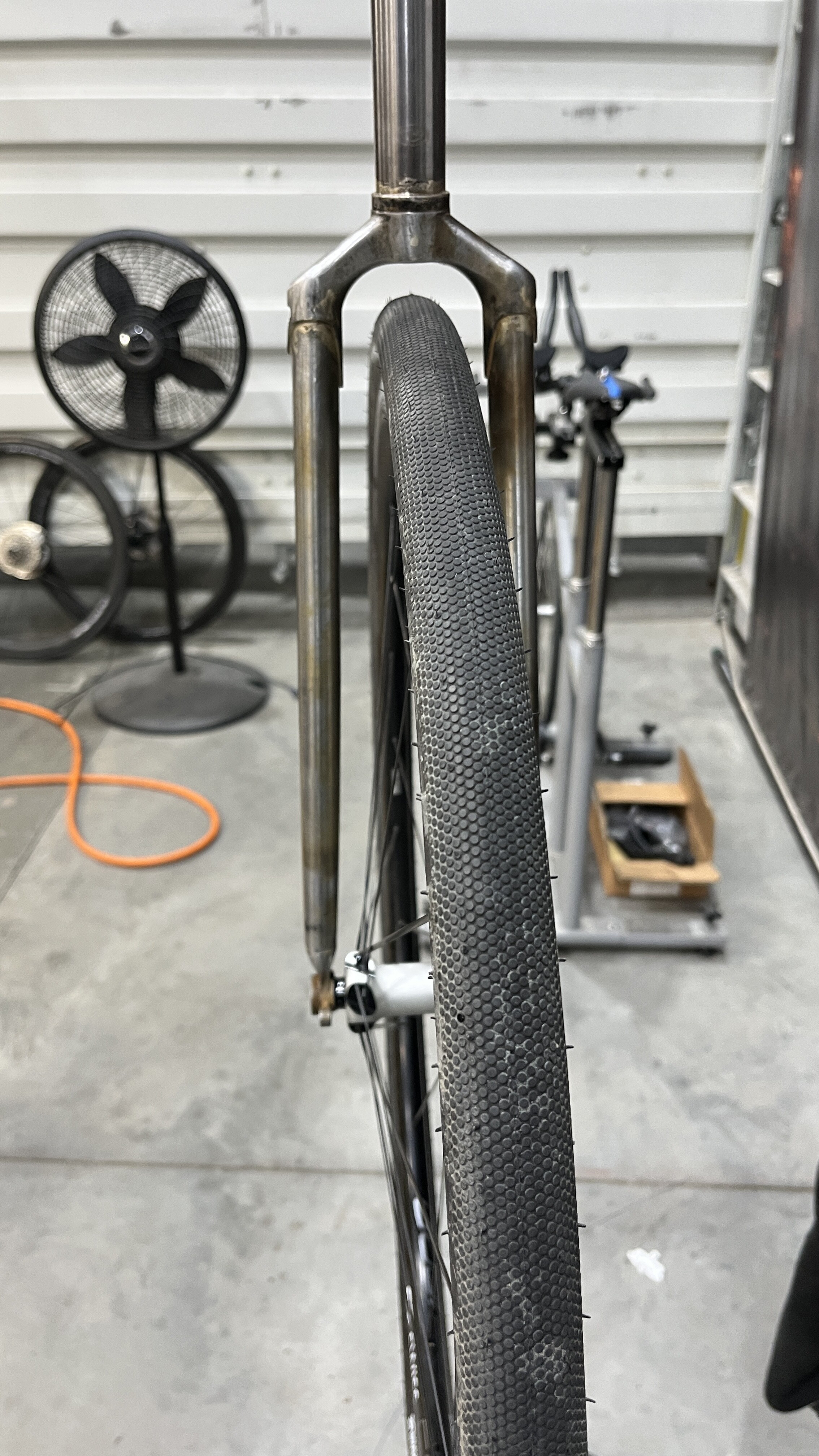
Apparently it’s a little difficult to fit larger than 30mm tires and SRAM omnium cranks. Still gotta play around with the positioning. My jig is tied up with another build right now so I’m just doing all the little things that I can do before I can put this one in the jig. Just thought I would share my progress on this future bike build.
If you couldn’t tell, I probably have ADHD and can’t concentrate on any single project without deciding to work on something completely different, then forgetting what I was originally doing, staying up till 1 am trying to make the stupid chainstay fit in the lug, then giving up and working on something completely different, etc. etc.
That dimpling looks very well done to me. Gut feeling it looks fine because people get away with using 5 or 6mm flat bar in those “drive side yokes”. What width of 0.8mm wall tube has equal stiffness to 5mm solid bar? I may work this out and if I do will come back and edit this.
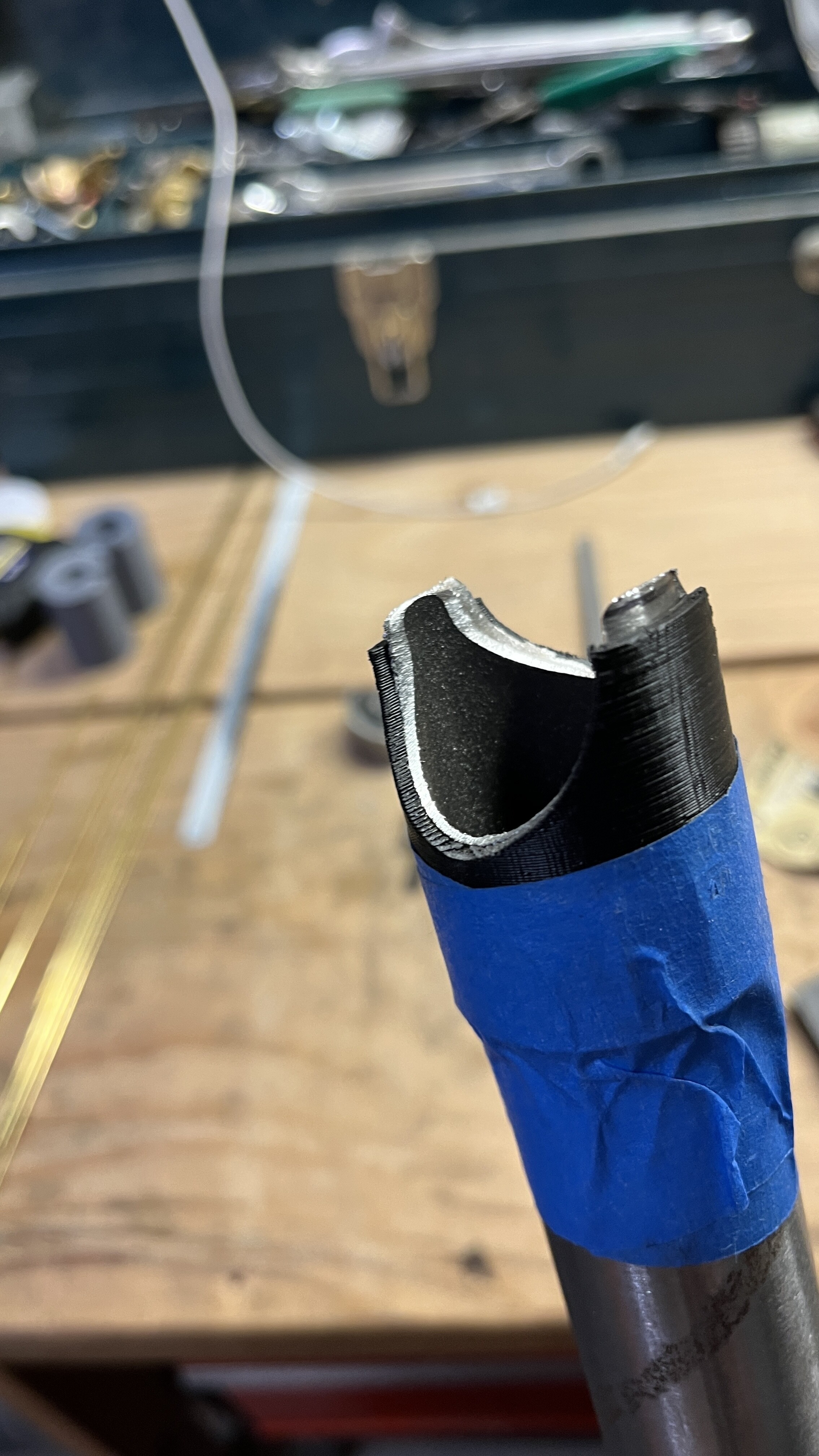
As I’m working on getting all of the tubing cut and mitered for the next few frames, I thought I would try the 3D printed cutting guide for a joint that I can’t print off paper cutting templates for.
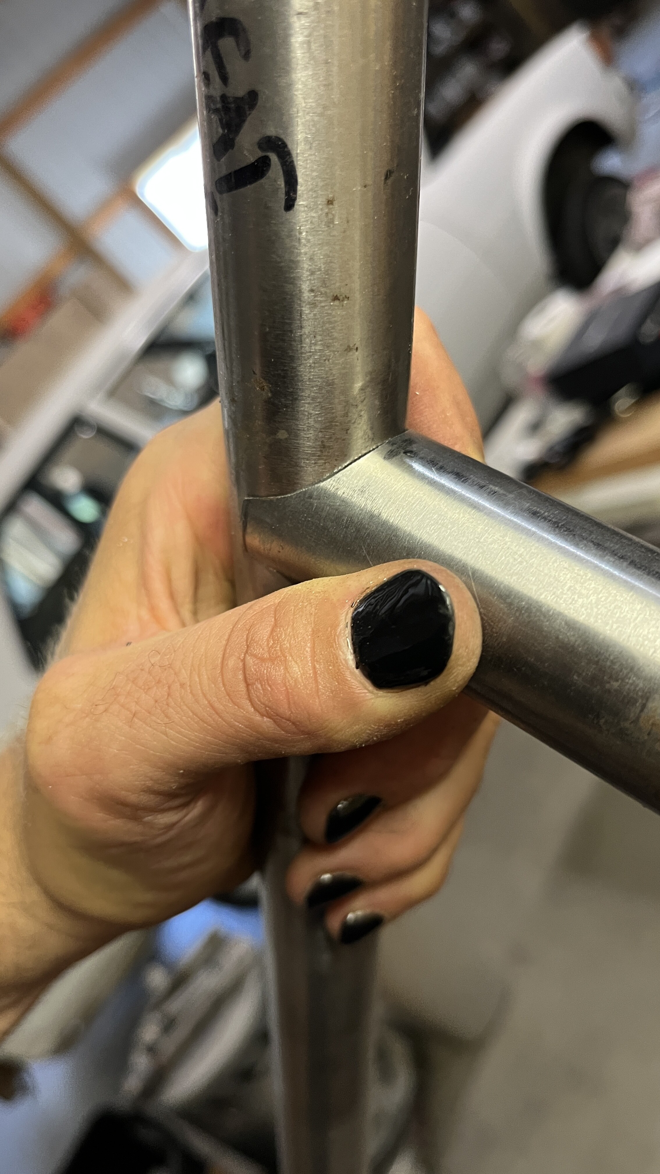
I gotta say, I’m pretty happy with how that turned out. I still have to set my jig up for this frame to be sure, but this was nice to see. I plan to have the seat stays butt up to the cutoff part of that top tube, then I’ll fillet braze it and file it all nice and smooth.
That’s really slick! Where did you did you find that 3dmodel?
I just made it myself since this joint isn’t suitable for the paper template program I use. If you want, I’d gladly make you whatever you need. For most joints, I use paper templates, but it should be pretty easy to set up a Fusion360 file that is configurable to any angle and tube diameter you are after.
Let me know. (I might make it anyway though since it sounds like a fun idea)
Thanks Spencer, very generous of you. I don’t need it now but hope some day to make another frame or fork. I’d say make it configurable because it could really help a lot of people out. I would certainly use it some day.
I made a bare bones simple cutting guide in a Fusion360 file.
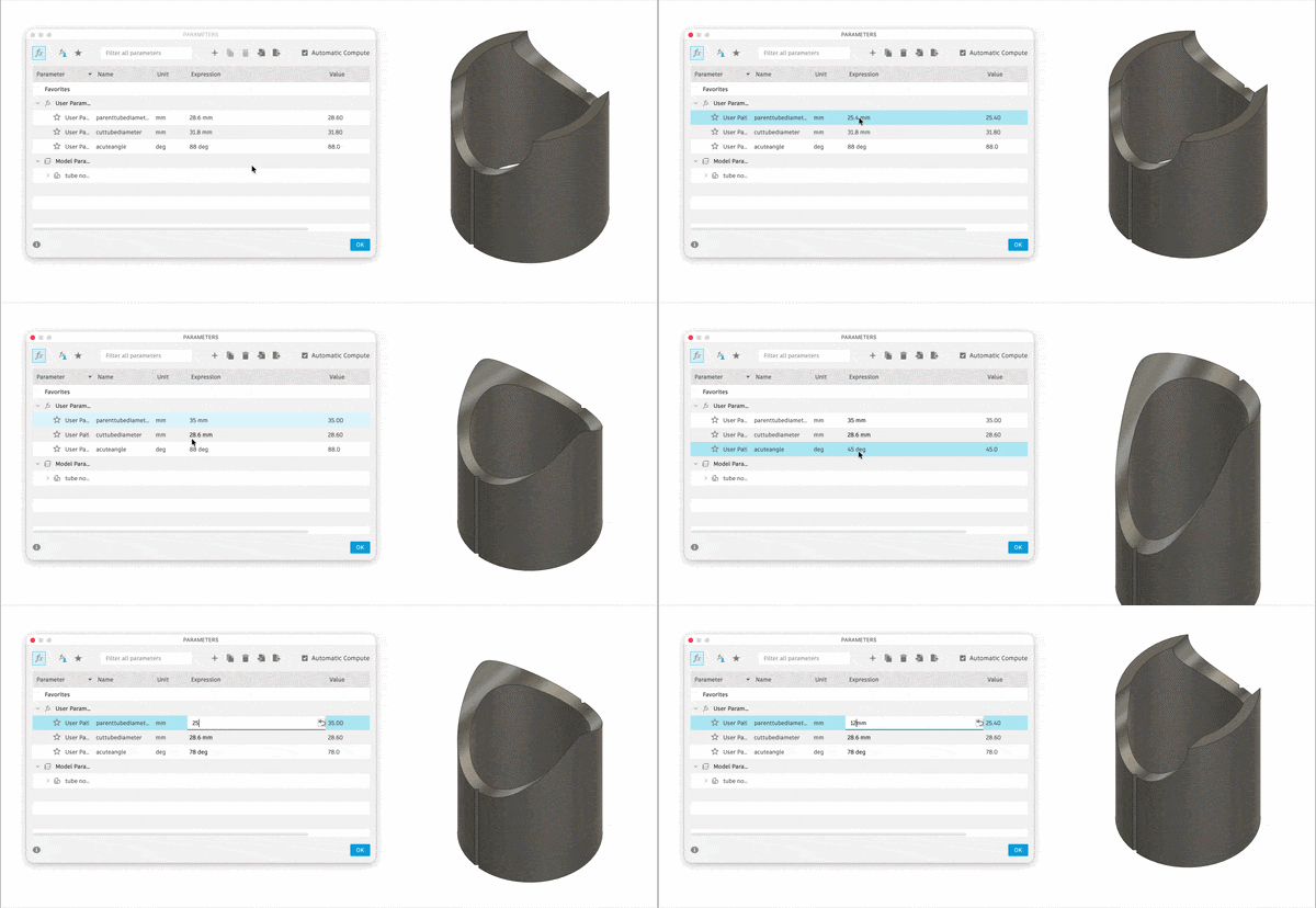
To use:
tube cutting tool.f3d (106.0 KB)
Right now the tool uses a .1mm offset to account for 3D printing tolerances. If you dig into the sketches, you’ll find it. So you should be able to 3D print the output from the tool without making any adjustments. But it’s a free tool, you can make any adjustment you want to make. I don’t care.
Are you just using that to trace, or keeping it in place as a reference while you work on the tube?
My process was
1- place 3D print on tube at the correct position and length and trace the shape
2- remove 3D print and cut tube close to traced line
3- place 3D print on tube and double check length measurement and rotational alignment
4- tape 3D print in place and file metal back to the 3D print, taking care to follow not only the shape of the 3D print, but the contour as well.
I didn’t take photos while I worked, but I can try to do it again soon if you want.
Makes sense, thanks for the info.
I finally got my acetylene tank back after a month of waiting for it to be filled (long story short, the filling machine broke so they exchanged a tank they didn’t technically have to since my tank is a different brand)
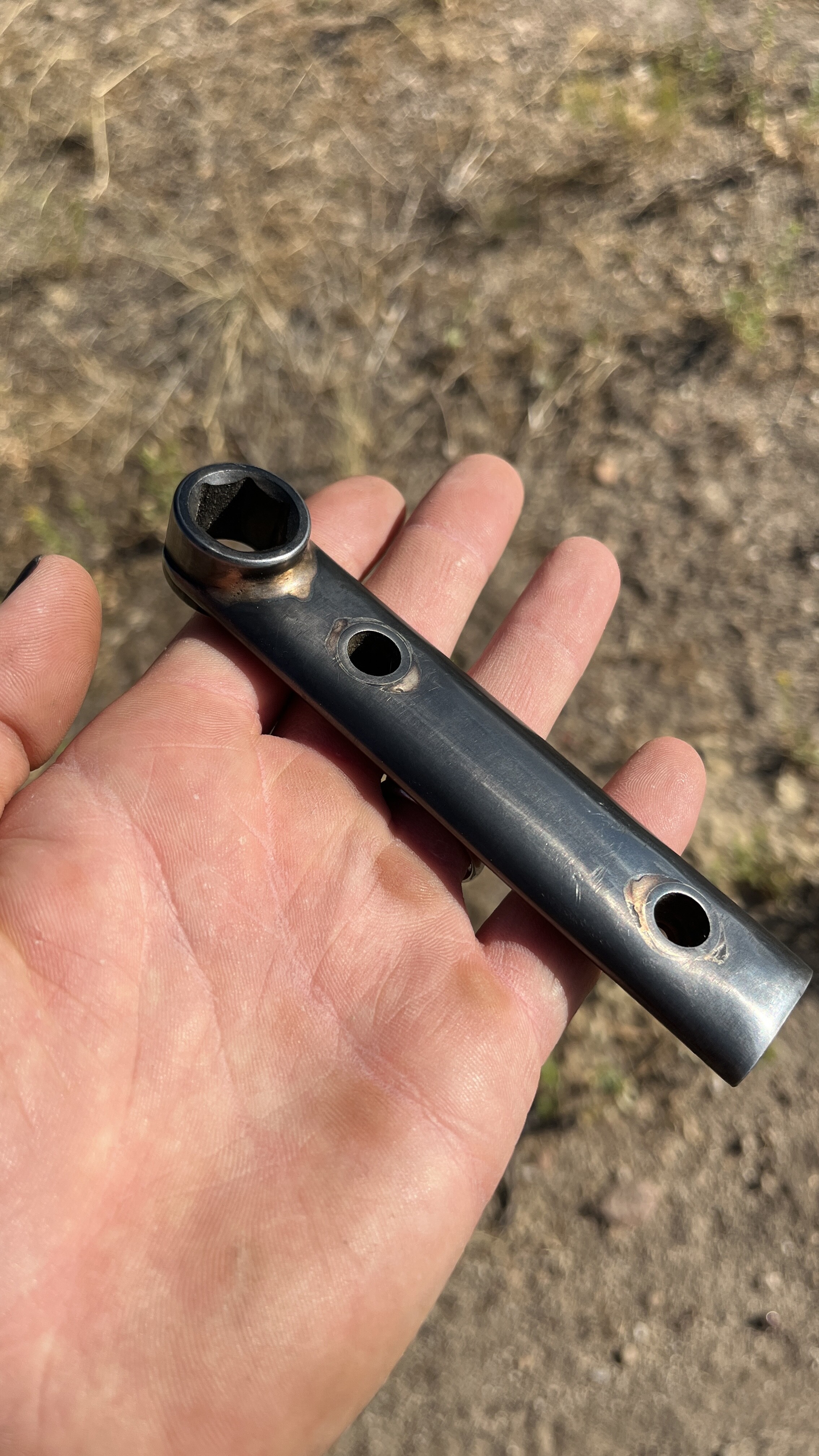
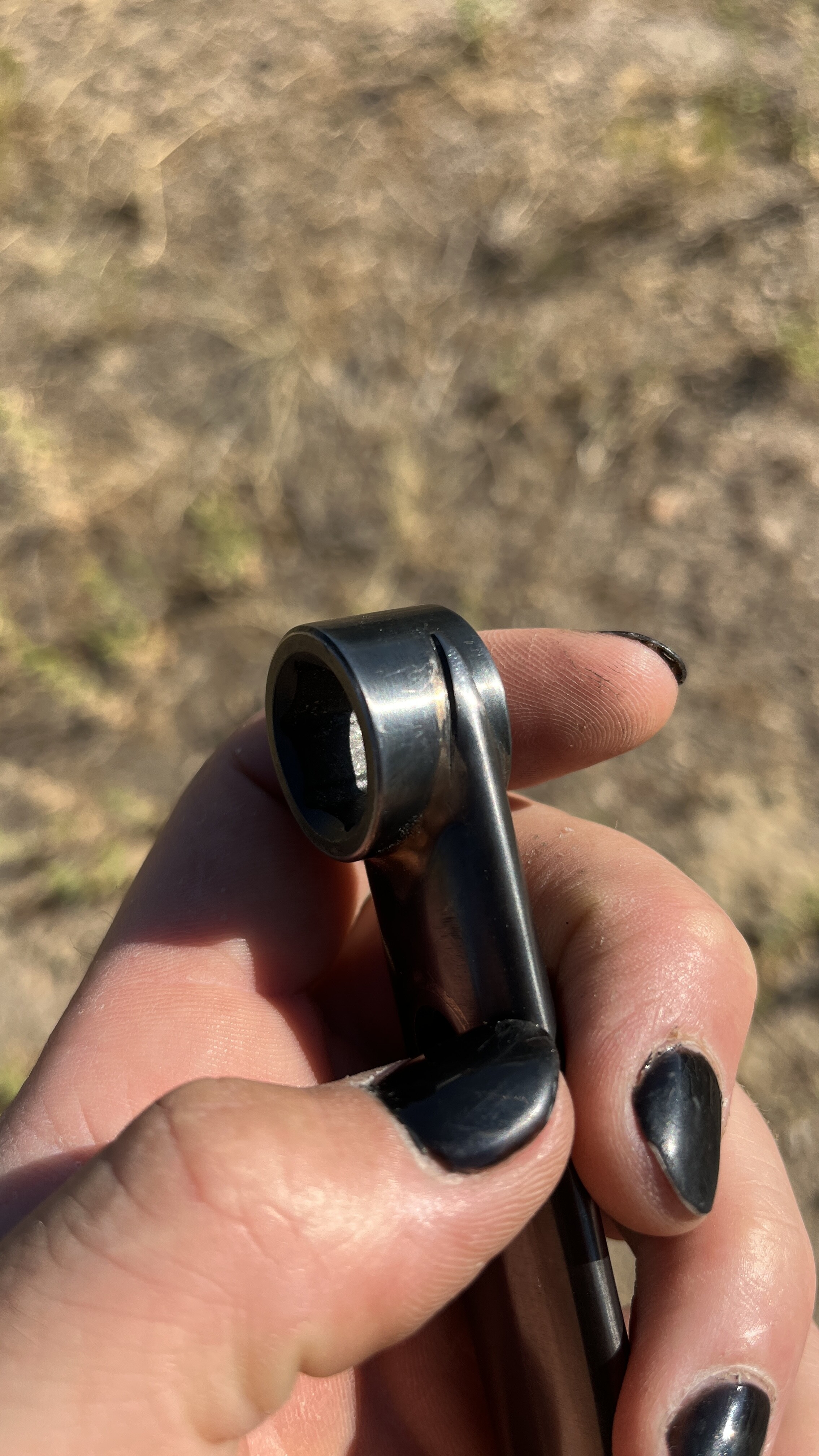
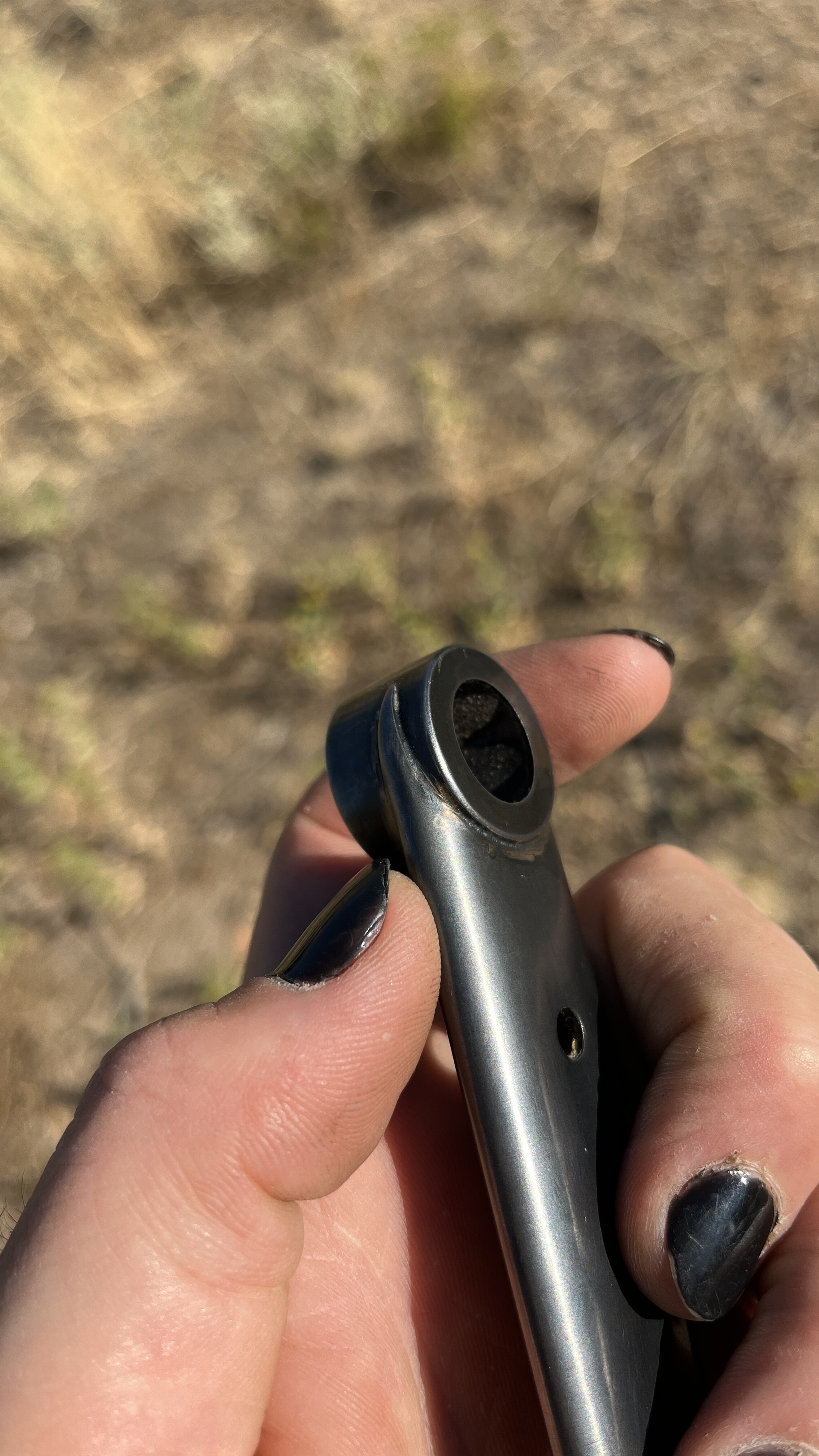
Anyway, I’m always a sucker for making my own 15mm wrenches. I buy the black oxide coated impact sockets, cut them down to size a little bit, sand off the oxide coating and then braze on a handle. It’s a fun little gift for any of my friends that still ride track bikes.
Here is my latest one. This one has a black oxide coating (insta-blak 333) that I then waxed.
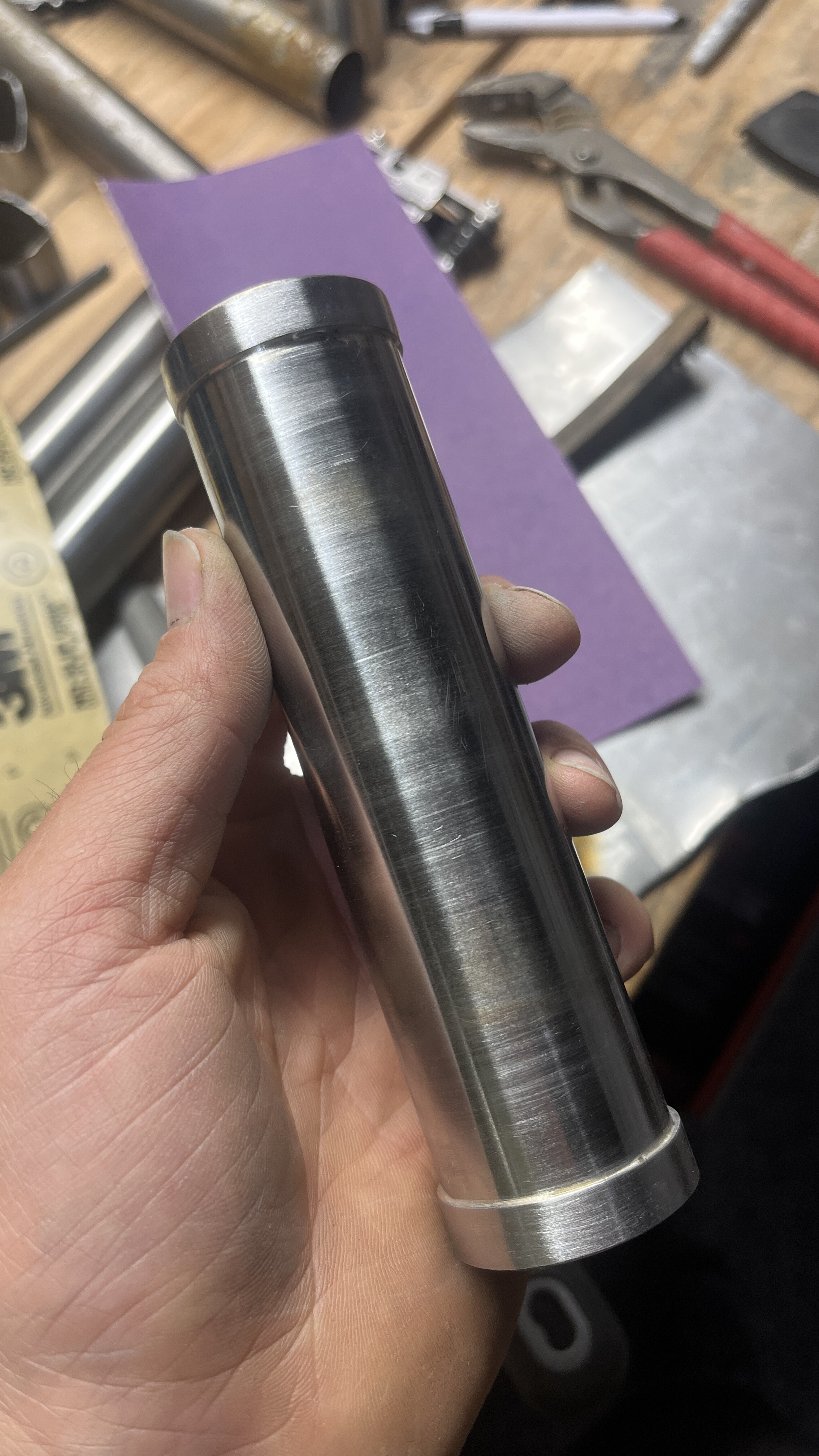
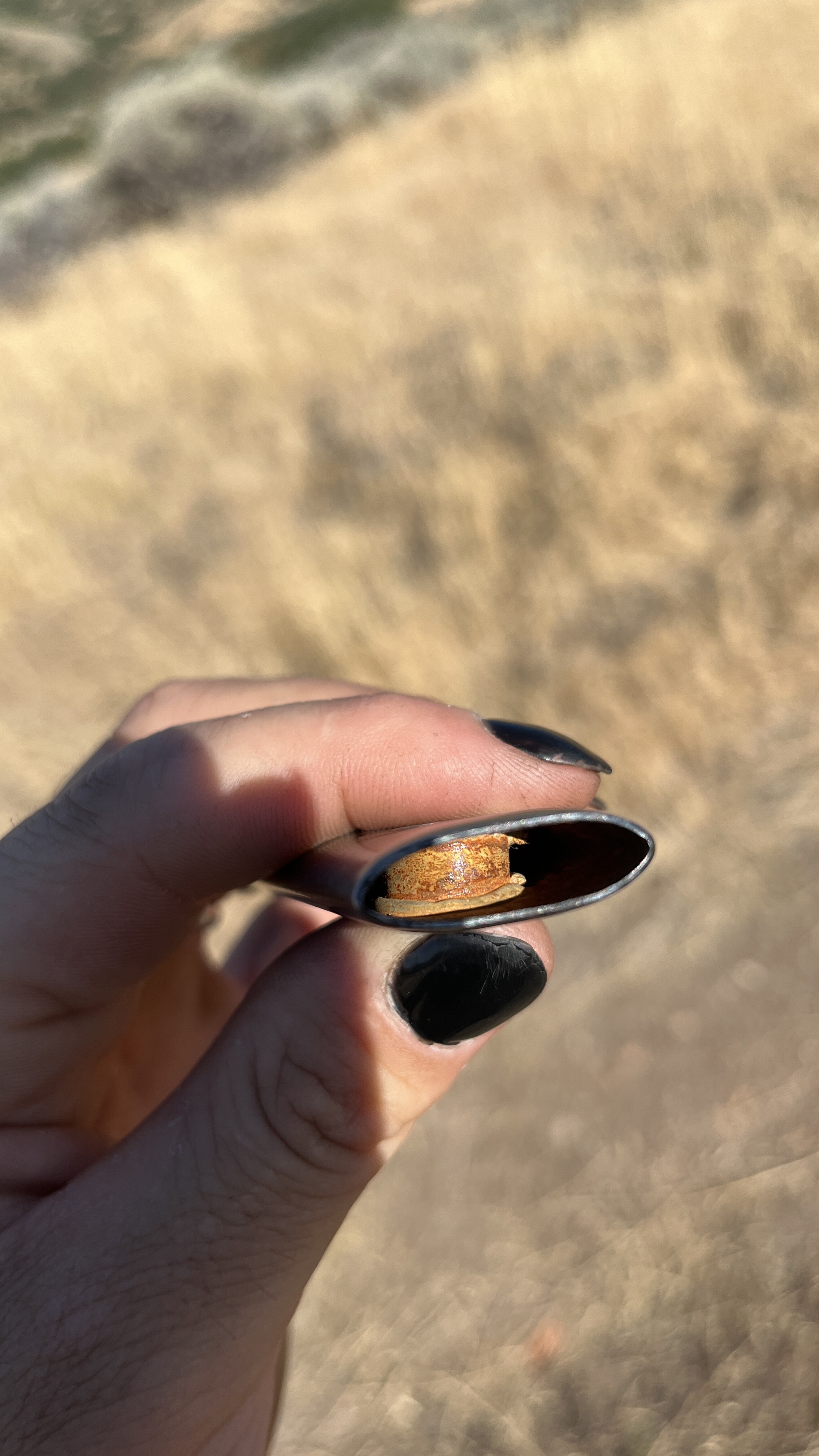
I had to get a little creative with the internal brazing. I made a little ring of silver that I had to hold in place while I slid the bolt head sleeve through the handle. Then I brazed that from the outside of the handle.