Does anyone have the technical drawing for the 3 bolt mounting interface?
1 Like
I don’t have it but I reverse engineered it for a chainring project. So, use at your own risk.
Nice. How’d the chainring project work out?
Do you have any clues on how to go about designing an oval ring?
It worked out well. Was fun.

I do everything in Fusion360 and I have no idea how I’d do it. My guess would be to figure out the math to make sure the circumference of a round chainring matches the circumference of an oval, but I don’t know how to calculate the circumference of an oval. And you’d want that circumference to be through the center of the chain pins.
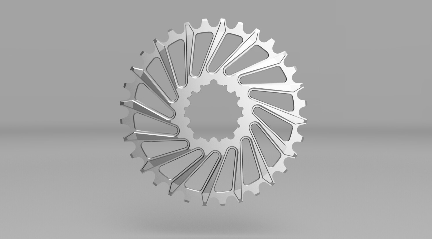
I actually went and designed a parametric model in Fusion360 that I can change offset and tooth count and it’ll automatically rebuild. Let me know and I’ll send you whatever you want.
6 Likes
Heck yeah those look bitchin!
1 Like
I’d would design an oval chainring by making 32 or whatever, 12.7mm long segments that are all connected and the end points are all on the oval. You can define one of the two main axis of the oval, and the other one will be driven by the geometry. Then from there you can build all the teeth on this polygon.
I hope that makes sense
4 Likes
Yeah, That sounds like a much easier way with less math. Just constraints within your sketch. Now you’ve got me interested and I’m gonna have to try it out.
1 Like
I’ve done pretty much exactly this.
Still don’t have a finished design but the bones are there.
After a bit of tinkering a while back I managed to create a parametric (round) chainring generator. Just type in the number of teeth and it spits out a model with my custom tooth profile. Now I just need to come up with a way to do it for oval as well.
Hopefully I can figure out how to make it so that I can control ovality, clocking and tooth count parametrically.
2 Likes
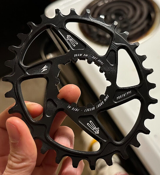
So I’ve built a handful of oval chainrings and have some tips. In fusion 360 I’ve found the easiest way to model an oval chainring is to use the method @Lester described, but I haven’t found a good way to make this fully parametric to the extent of controlling the number of teeth. I prefer to define the ellipse minor axis diameter and the oval power angle. Once you add in the number of teeth and define their spacing, the major axis diameter gets defined.
I’ve also found that modelling the teeth can be a bit of a PITA depending on how complex you decide to make them. My recommendation is to break the tooth profile up into multiple sketches and project entities across sketches. I’ve included a simplified F360 file of the base sketch and the spreadsheet I made when i first started looking into modelling oval chainrings.
30T Oval Example v1.f3d (1.9 MB)
Oval Chainring Spreadsheet
Also I’ve included some DXFs of the direct mount splines I’ve reverse engineered. Take those dimensions with a grain of salt, but I have successfully test fit them on a few cranksets.
Sram DM 3 Bolt Chainring Spline.dxf (10.5 KB)
Shimano DM Chainring Spline.dxf (11.6 KB)
Race Face Cinch DM Chainring Spline.dxf (9.0 KB)
4 Likes
The talent here is incredible. Thank you for all the “clues” and beyond.
@Kitchen thank you for the drawings, siiick sprocket!
3 Likes