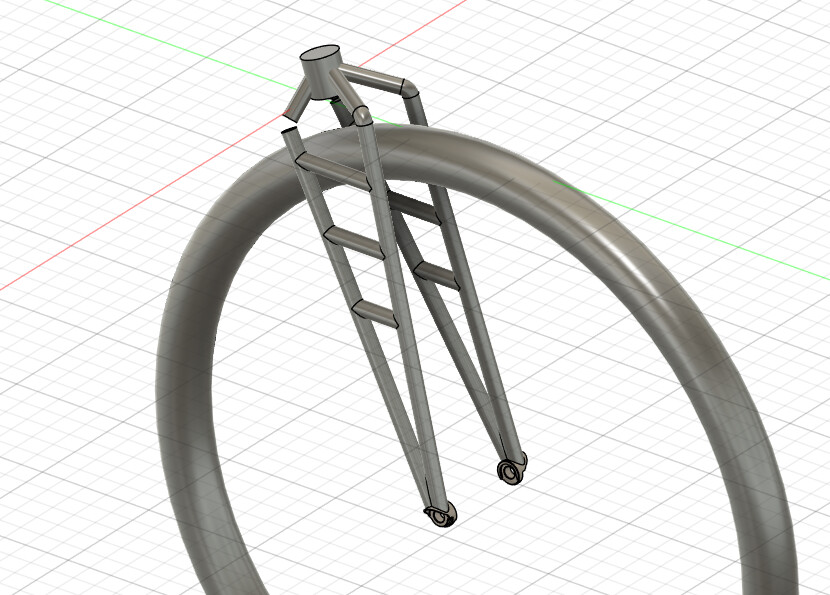
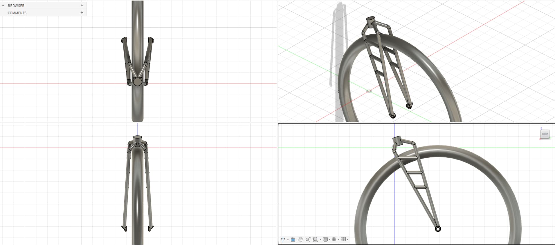
Hello, I am designing a new fork and trying to apply a few concepts that I wanted to explore.
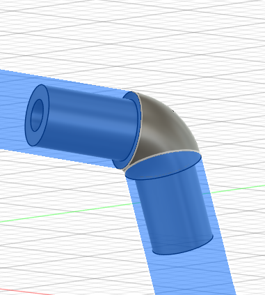
The plan is to have all tubing laser cut and the “elbow” be 3D printed and brazed on.
The tubing is already sized to match what is available from the laser cutting company, once it’s all welded, I have calculated a target weight of ~1200g that is comparable to other sturdy steel forks in the market.
This is a 100x12, 700C fork, clearance for 2.1in tires.
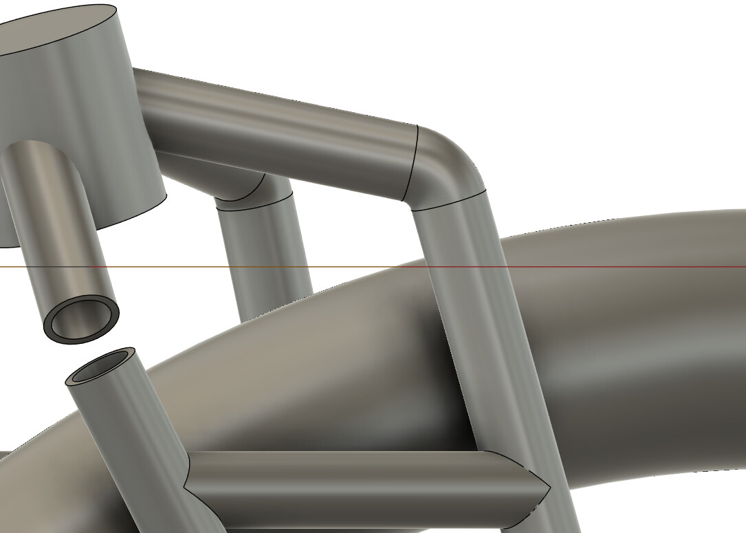
Before I hit send on the 3D printed elbow, here are my doubts:
Would the 3d printed elbow be strong enough? Are there issues on the elbow design?
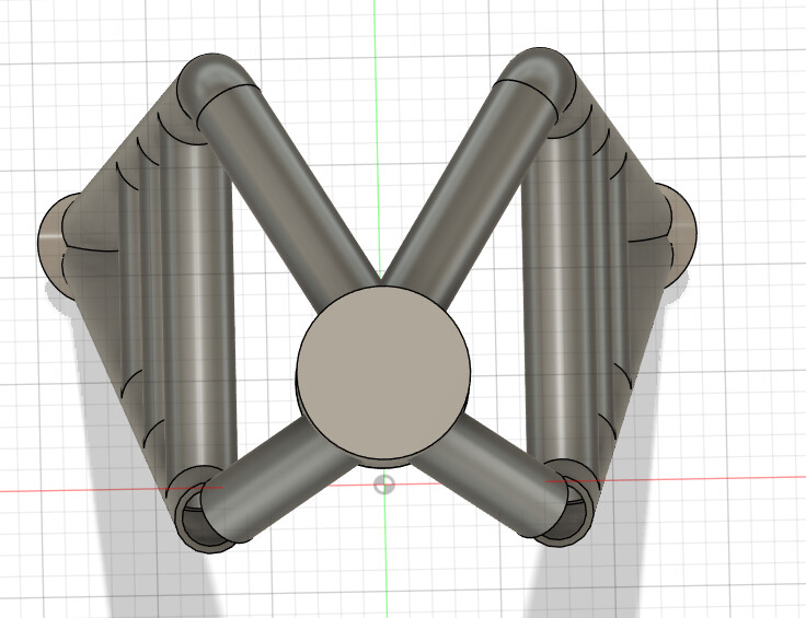
Should I add a brace between the front two legs across the tire?
I am using 0.625in tubing with a 0.065in wall, that is thicker than I would like (oshcut.com) - any other easy to use tube laser companies that have smaller diameter/thicknesses?
I don’t think you need a brace across the top as you already have one at the bottom (the axle). Unless you want a place to put a fender mount, but I’d probably just put a bottle boss on the bottom of the “spider” at the top.
Sounds like it should be pretty strong but this is a totally uninformed opinion Can your CAD program do FEAs?
Great looking design. I can’t comment because I have no experience with 3DP, but am gearing up for my next frame.
Are you brazing or TIG? If TIG- what do you see as the purpose for the insert into the tube?
I’m interested to hear your experience using the laser cut tube service. Could be a great option for tricky miters for those of us without extensive shops.
The insert of the “elbow” part is there to make it sturdier, when connecting tubes like I am doing, you have to have an internal sleeve otherwise the connection would be weak.
The plan is to braze the elbow in the tubes and then braze everything else (or TIG it, haven’t decided yet)
I could be totally offbase here but I think tig welding is the suggestion when using 3DP parts in stainless but you can get away with brazing (using the right technique). This is still pretty new so perhaps there isn’t a general consensus
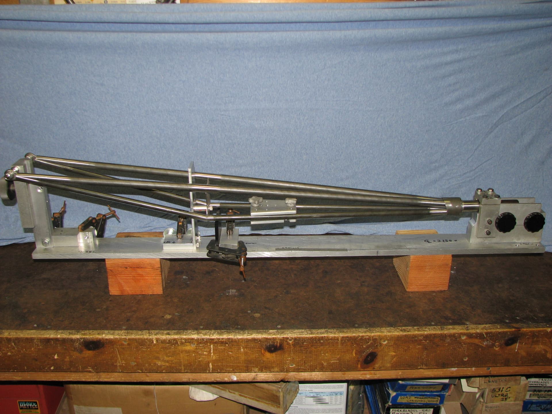
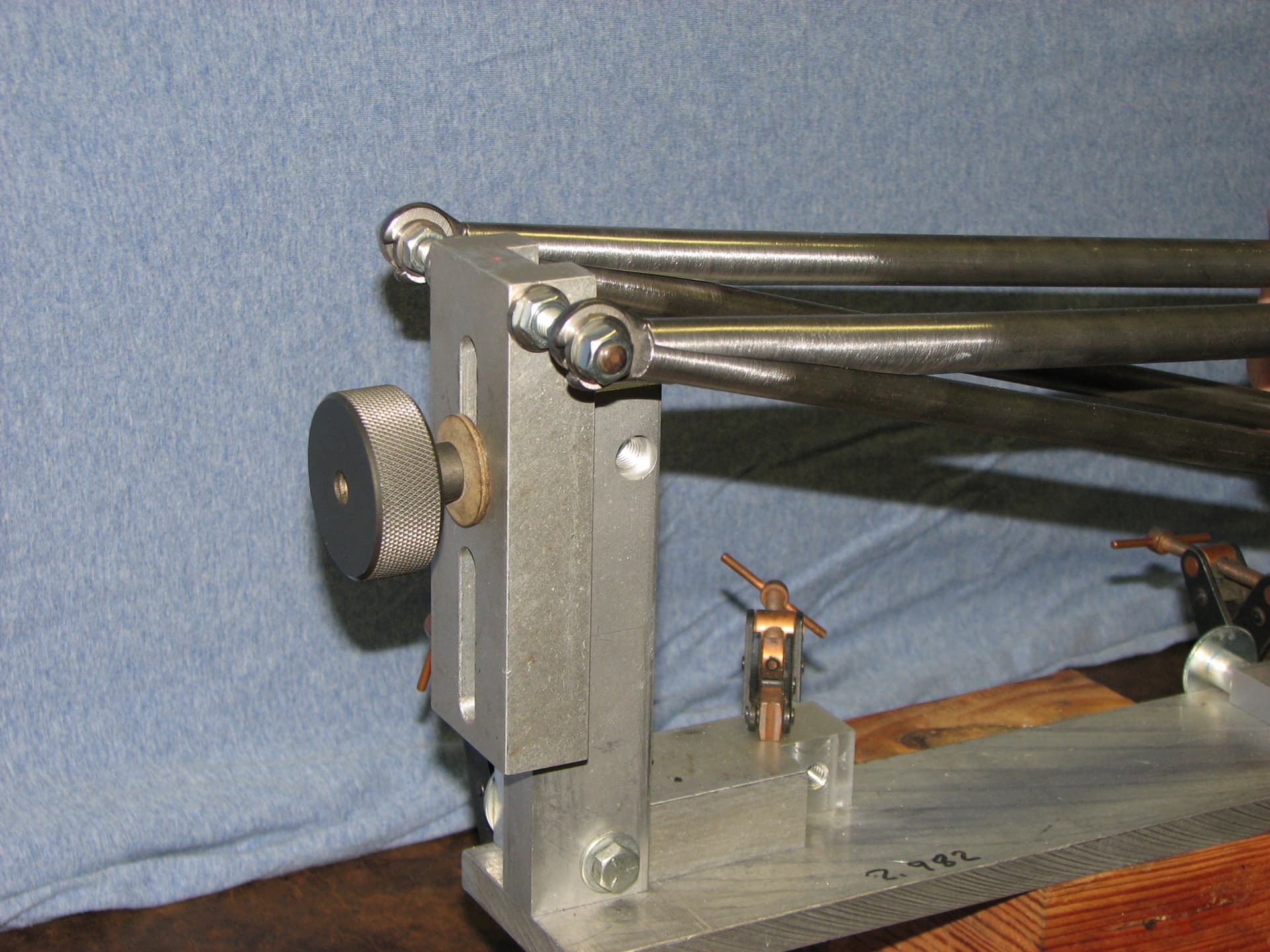
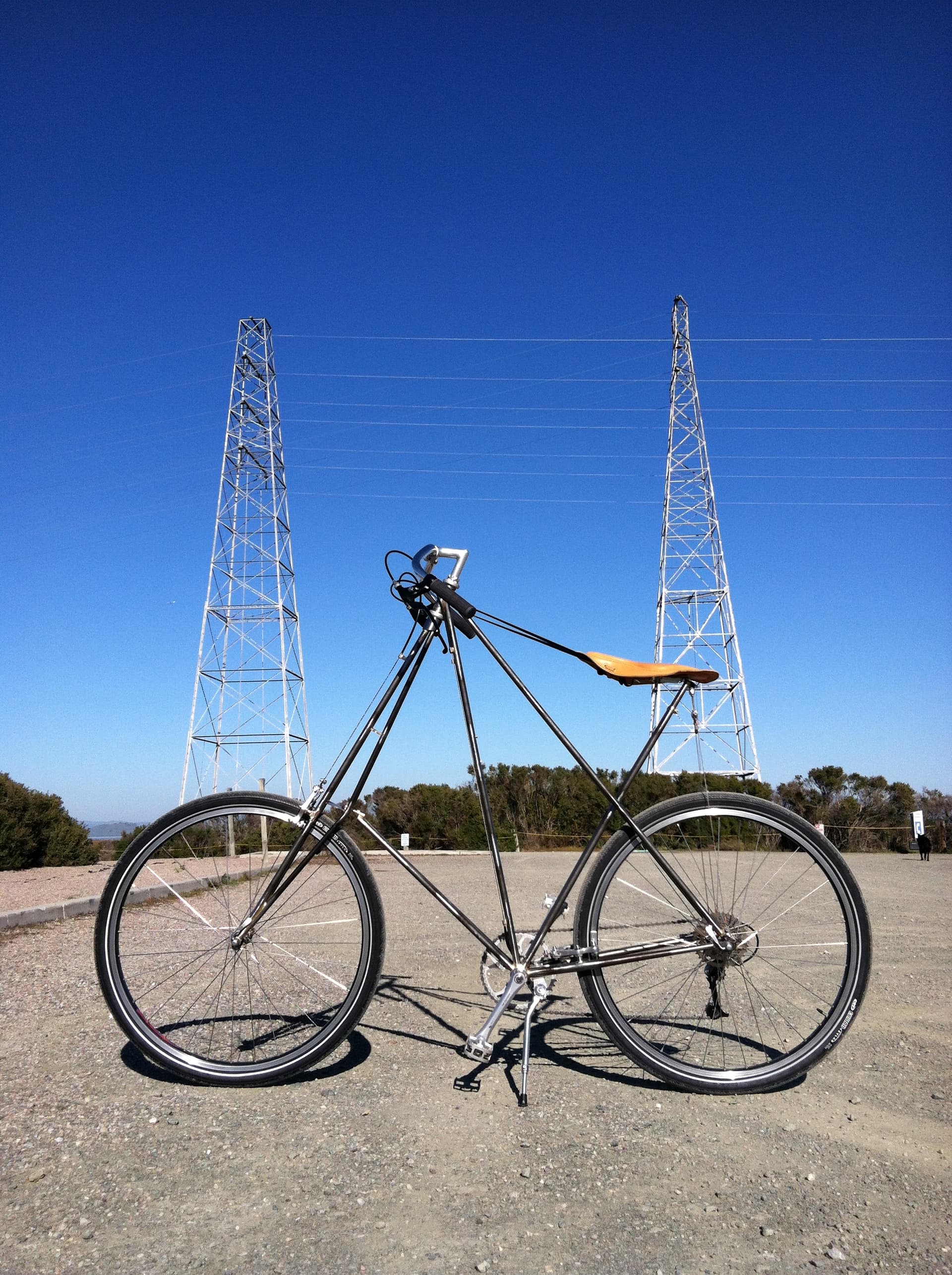
Not a CAD guy here but do have a bit of experience with truss type forks. Here are my thoughts- .065 is more wall thickness than needed, my guess is that .035 would work fine. I would consider eliminating at least one of the horizontal side braces and maybe even replace them all with a single diagonal brace. The cross brace at the top is a good idea, but better yet perhaps instead of printing the 4 elbows you could consider printing it as a more traditional crown with 4 spigots. Some 5/8 .035 from Aircraft Spruce and careful work with a hacksaw and files could get you a lot farther than you may think. Just opinions, YMMV and please post your progress whichever way you go. Possibly some inspiration below, not really a fair comparison though as the Pedersen frame this fork is for has an effective 18” head tube (due to having a Heim joint much lower down).
I redesigned it to use 5/8-0.049” tubing and 1/2-0.035” braces, overall weight went down quite a bit.
Waiting for a quote but if it’s too high, I am thinking of 3D printing notching guides out of PLA (in my own 3D printer) to help me cut the correct notches and then bend the tubing manually instead of having 3DP metal parts - stay tuned
If you are based in the US, this place will take tubes that are shipped to them (either from a distributor or yourself) then cut them to your spec. If you are out of the US, you still might be able to do it but it will probably be hard/expensive. I imagine Europe and Asia have similar services https://www.ptlmfg.com/
the good: I optimized the elbow and now I can have it CNC’d instead of 3DP for the same cost but I can actually use 4130/4140 steel that would make the part much stronger and easier to braze.
the bad: I reached out to Precision Tube Laser (ptlmfg.com) and I send them my designs asking to quote me in two different tubing profiles. Precision pricing is very competitive with others and they have the perfect steel specs I need, however, each leg in my design needs close to 3ft of steel tube and the machine needs 6in of space to hold the tube, that means I cannot order two 3ft long tubes or one 6ft long one but I need TWO 6ft long tubes, increasing my cost quite a bit (this happens with all manufacturing quotes I got, just Precision was kind enough to answer all my annoying questions )
Talking costs:
4 CNC machined elbows in 4140 steel would cost me around 115$, the rest of the tubing, pre cut would run about 260$, plus dropouts ~50$. For a total of 425$ excluding shipping and taxes, let’s call that 500$ even.
For a one-off for my personal hobby it seems too steep (making a small batch and selling them would be doable with some economies of scale).
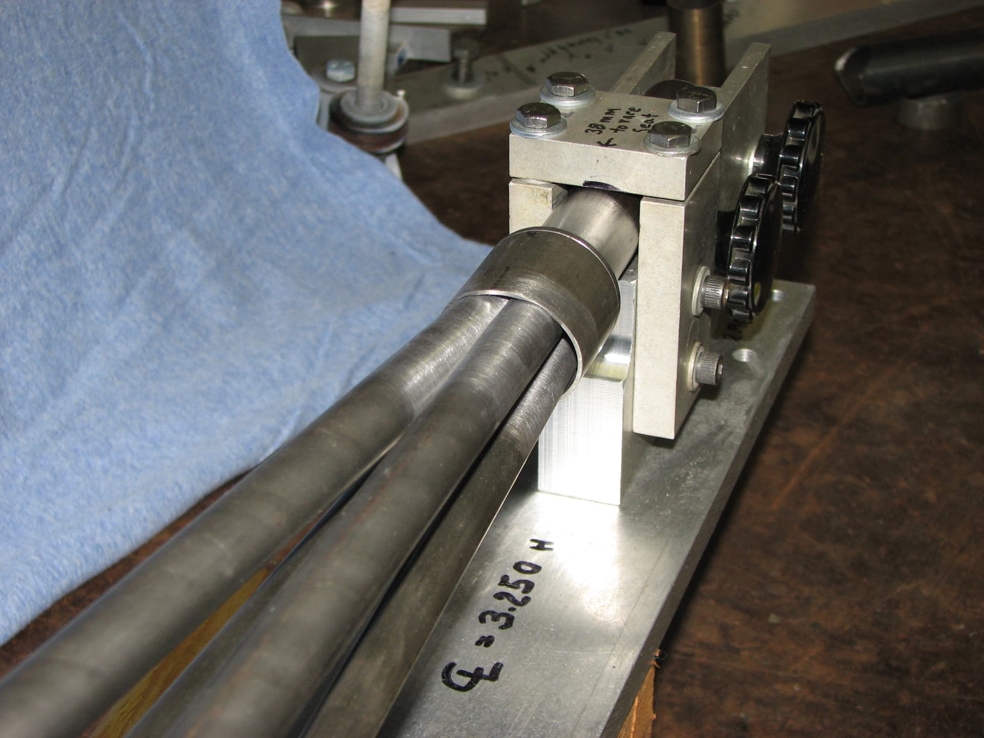
I am thinking of ordering the tubing and work it myself, trying to figure out some clever 3DP guides that would help me with bending and notching
I am not sure, I am trying to see if I can optimize my lengths to fit in a single 6ft piece of tubing.
If I was to build many of them, I would probably build a jig to cut all the pieces quickly
I can share the step file for the elbow with all the reference points if you want it
What tooling do you have or have access to? The main vertical(ish) tubes look like they could be a single tube with a single bend (maybe not as tight as you have on your drawing). The cross pieces look straightforward to mitre, and it looks like there are only 2 different cut angles, which would make setup pretty quick.
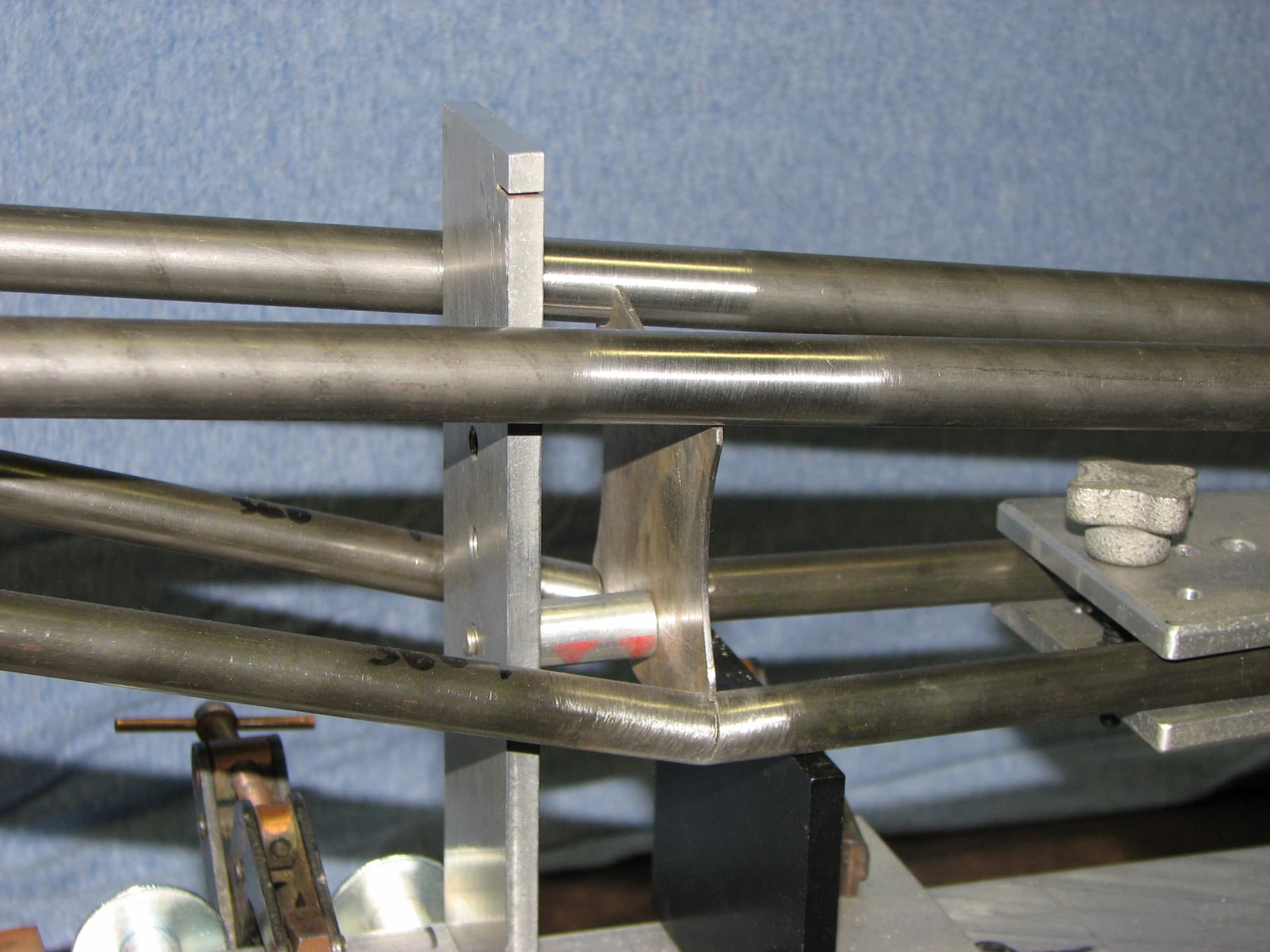
For the steerer mitre on the 4 tubes, I’d be tempted to build a fixture to hold everything together (maybe with some temporarily welded additions), and mitre that whole section in one go with a holesaw.
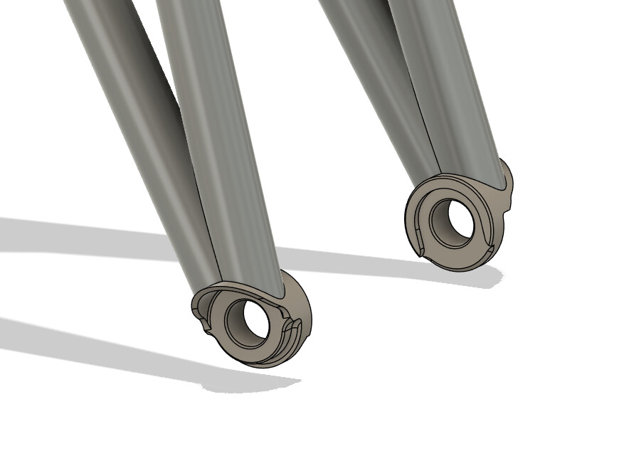
The long, shallow mitre on the bottom of the legs is something I’d try to design out. Doing those cuts I find a real pain.
For the steerer mitre, I believe I have a solution that should work and I plan to buy that Vevor bender on amazon that a lot of people here seems to have (my current benders don’t bend 5/8).
How would you redesign the leg bottoms to avoid that shallow miter?Bending one leg? Looking for inspiration, I am also not married to those dropouts, I can use different ones
Don’t over think that shallow miter. One tube stays untouched and holds the dropout. The other tube gets cut with a hacksaw and there is actually not very much filing involved. (4th pic in my post above)
Basically a very steep seat tube/seat stay junction and lots of meat left for braze or weld due to length. Plus, IMHO, it looks pretty elegant.
that miter is more challenging than the rest because it’s not only long but it’s also slanted on the side of the wheel, I do believe that with a 3DP block I could file that quickly, however, I am all ears on changing the design to improve manufacturability.
A different dropout may allow me to increase the angle between the fork leg and reduce or remove some miters. Thankfully I can mock it up with F360 for free before pulling the trigger
Not arguing here, just thinking out loud. Looks like your design shows the tube(s) being straight with no other miters. If so, the mitered tube can be rotated around the unmitered one to achieve the slanted effect.