I’ve been trying to wrap my head around the mathematics of figuring out how “bendy” a given object will be. As I understand it, this is related to the mechanical properties of stress and strain. I think I understand those principles, but then the theory gets pretty deep into things like moments, area moment of inertia, and polar section moduli. I admit my eyes start glazing over a bit.
I got through my degree in electrical engineering by relying on real-world examples to understand tricky theoretical problems, so I’m hoping the simple tubes in a bike frame can help with these mechanical concepts.
For example, I’ve been trying to figure out how “bendy” the yoke I whipped up will be in comparison to a regular 19.1 x 0.9mm chainstay.
At its thinnest section, the yoke is roughly an ellipse with the major axis at 19.1mm and the minor at 11.5mm. The wall thickness is 2.1mm. The yoke is also made of 316L stainless vs 4130 so the modulus of elasticity will be different between the two materials - 193GPa for the yoke vs 205GPa for the tube.
I’d love any pointers y’all have on where to go from here. I’ll keep updating this thread as I figure more stuff out as well.
This area of study is called “Solid Mechanics” I will take a crack at this with a more bike-specific answer, but for now, I think this resource is the best I could find.
I think the key to building intuition about stiffness is understanding the area moment of inertia and being able to visualize its impact on the flow of stress in an arbitrary shape.
Eva
The book that really helped me was design of weldements. https://www.jflf.org/ProductDetails.asp?ProductCode=DW
It’s still in print and also there is a pdf version floating around.
It’s from the era of trying to get engineers and designers to embrace welding instead of casting for making stuff.
So it has a lot of math in it, but also a lot of explanation geared at creating the intuition you are looking for.
Just the section on making flat tables should be required reading.
Hahn
I’ll second the recommendation for Design of Weldments. It’s been years since I used it in school, but I remember thinking it did a good job of developing physical intuition in addition to explaining theory.
Any use of FEA comes with a lot of caveats, but if you’re interested in determining the stiffness of a relatively complicated geometry, the Fusion 360 simulation tools might be worth exploring. You’ll have to model a representative (sub)assembly, figure out how to apply useful loads and boundary conditions, have a good mesh, etc., but it may be a decent way to check that your intuition is guiding you in the right direction.
I’ll stress that having some intuition for what to expect is important before diving into FEA. It’ll help you interpret the results, check that they’re reasonable, and guide design decisions (ultimately what you want, probably), so if you’re starting from zero the solid mechanics references are the best place to begin.
I’ll echo everything mentioned by @Daniel_Y and @photon. Especially the part where FEA can get you answers but you have to know whether the answers make sense or not. And validate them too. That’s the part that often gets left behind (by myself as well).
The bicycle as a vehicle is a surprisingly complex problem as it is so dynamic and there are still quite a few things about them that we don’t understand. The good news is that we don’t always need to understand the why and a traditional double-diamond frame is a very strong design.
When it comes to evaluating a yoke, that’s one of the trickier things to evaluate. There are a lot of forces going through it and the total stiffness of the system is going to be dependent on the hub, axles, dropouts, and seatstay location. Accordingly, it makes sense to ask what is important to you;
Total assembly stiffness (lateral, vertical, or torsional)
Individual part stiffness (lateral, vertical, or torsional)
Rear wheel Installation stiffness (how stiff the stays are before you insert the rear wheel)
When you decide on the answer to which you want to learn about (and yes, all of the above can be an answer but it will take time) then you can break out the different loads that will be introduced to the system and evaluate based on that. I may be speaking out of turn here, but this is where a Free Body Diagram will be especially valuable and help organize what you are trying to discover.
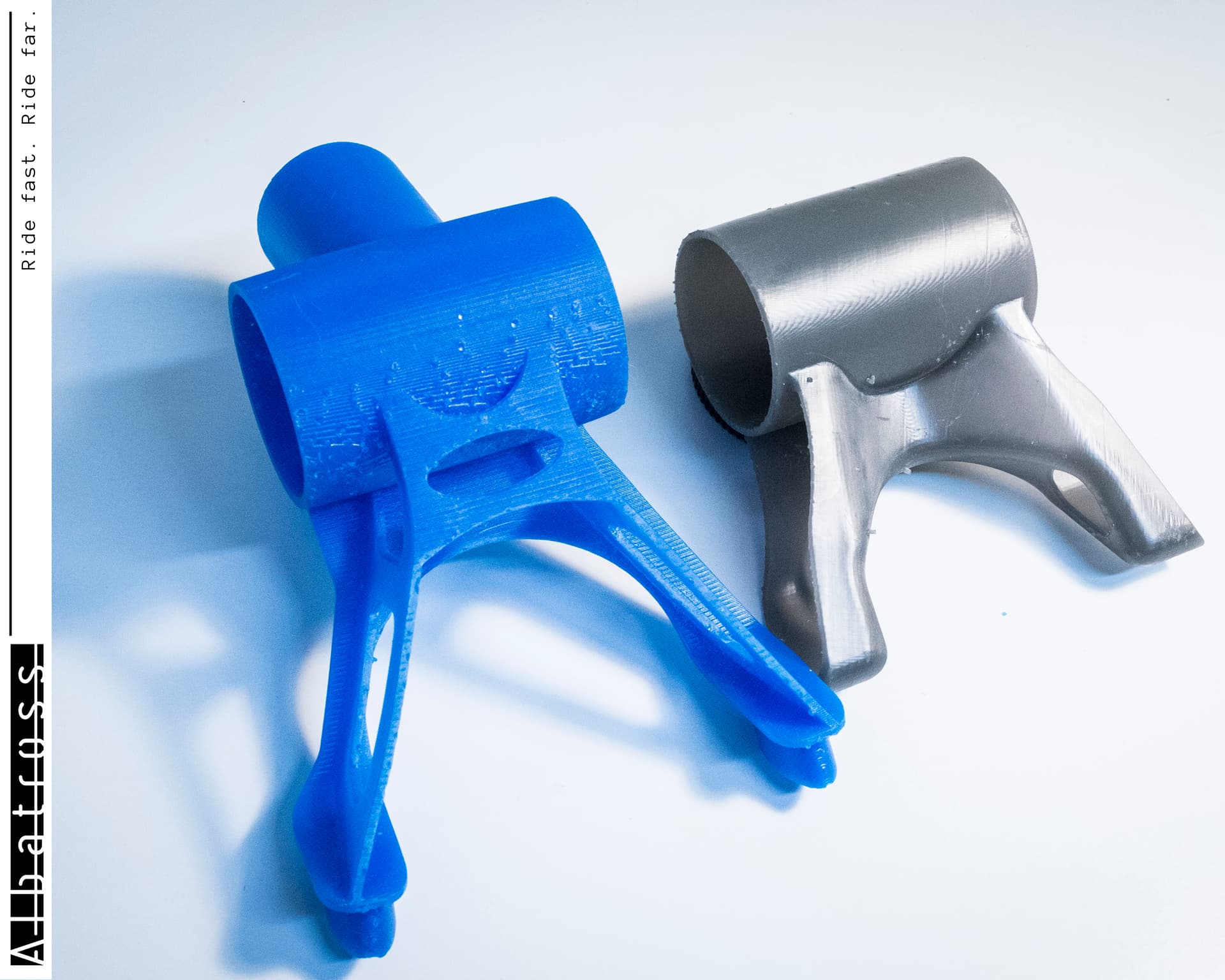
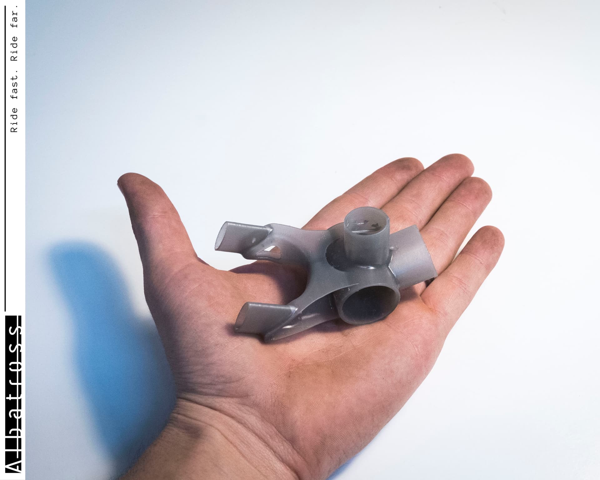
Now, what are some of the things that you can do right now to point you in the right direction that doesn’t require a few months of study? Something I’ve done in the past as a sanity check was to 3D print models of the components that I was comparing and just played with them to see which ones were stiff and which ones weren’t.
This won’t give you a numerical answer on which is stiffer, but it will give you a directional and comparative answer on which is stiffer. This is because if all of the models being compared are of the same material, the stiffness is driven by geometry which is what you are trying to find out. There are many reasons why this isn’t 100% accurate but for a comparative answer, this will help you out significantly and give you a better sense of which is stiffer than the other.
The last recommendation would be to just build it. Depending on what you are valuing (time vs. capital) the time saved by building a prototype compared to sorting out FEA could be worth the additional cost of the prototype itself. It’s always a tradeoff right?
Hope this helps and if there are further detail questions that you have, let me know and I’ll be happy to put together a response.