Nice job! A lot of customization in that CAD as well as 2D drawings, impressive.
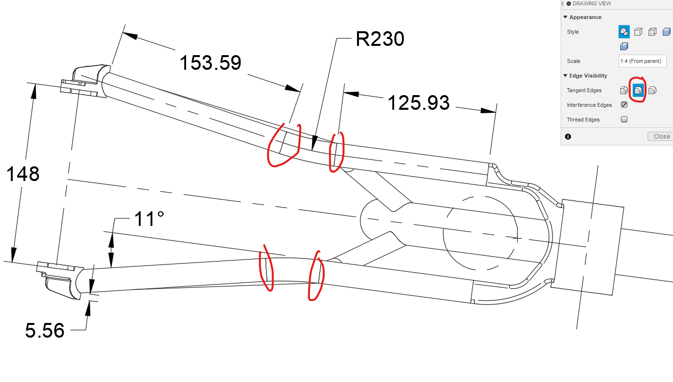
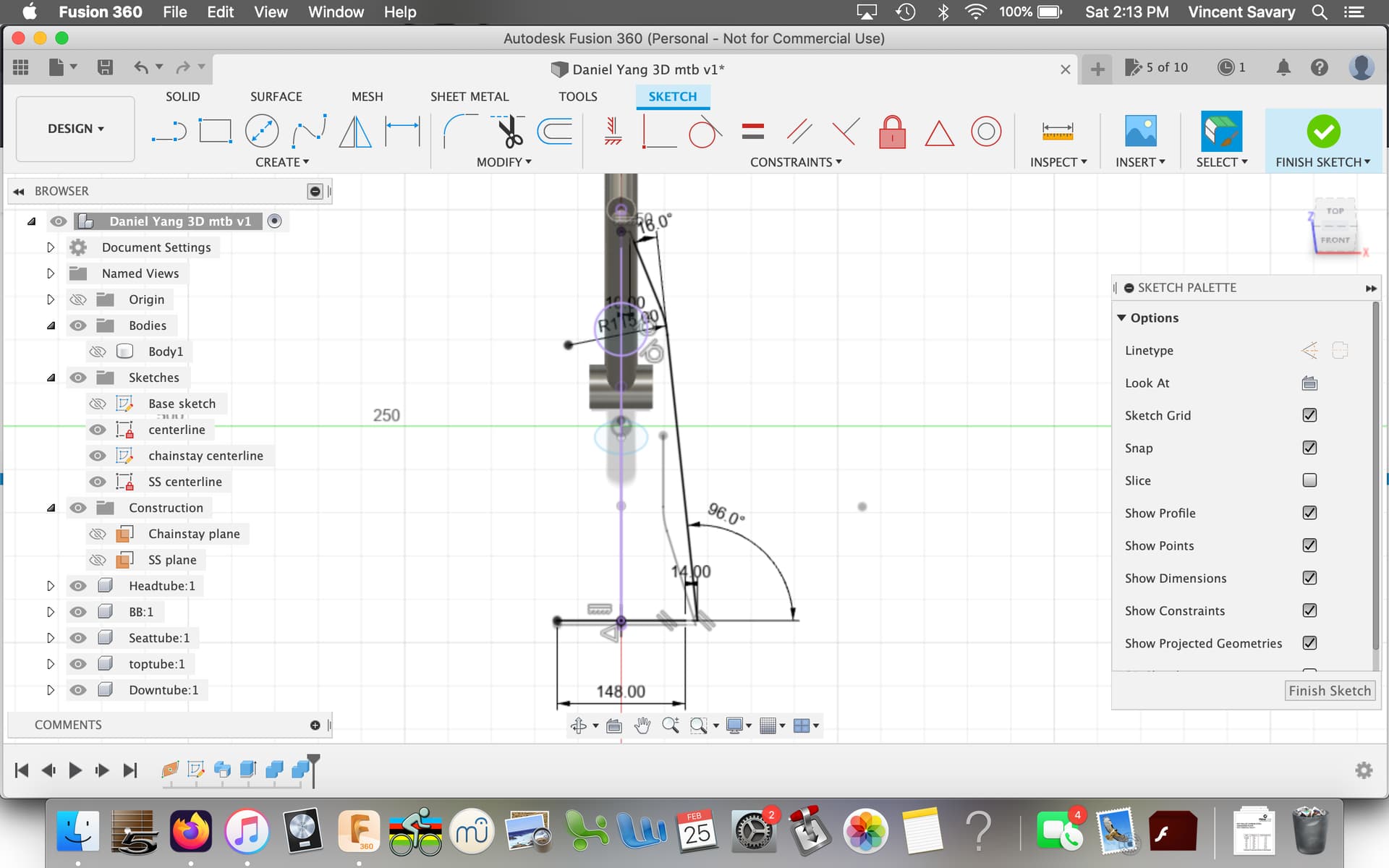
Just a tip, not sure you are aware, but if you toggle this tangent edge button, you get the bend tangents. That will allow you to call out the bend distances:
Thank you very much for that turitoral, I have been working with Bike Cad and hat a hard time meassuring, the exact locations for the miter of the SS and the CS.
Sure, heres a quick write-up. I am currently working on a 3D printing chainstay manipulation workflow.
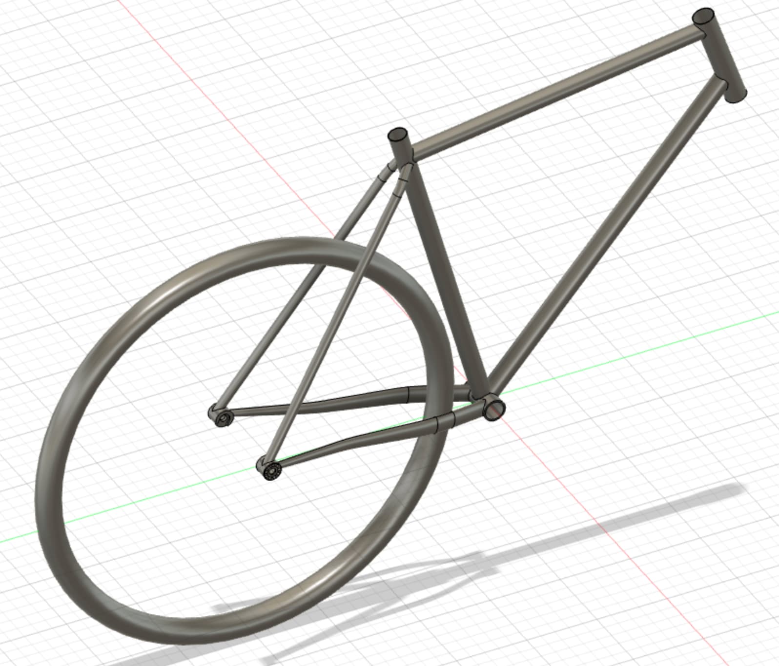
1) Creating the chainstay:
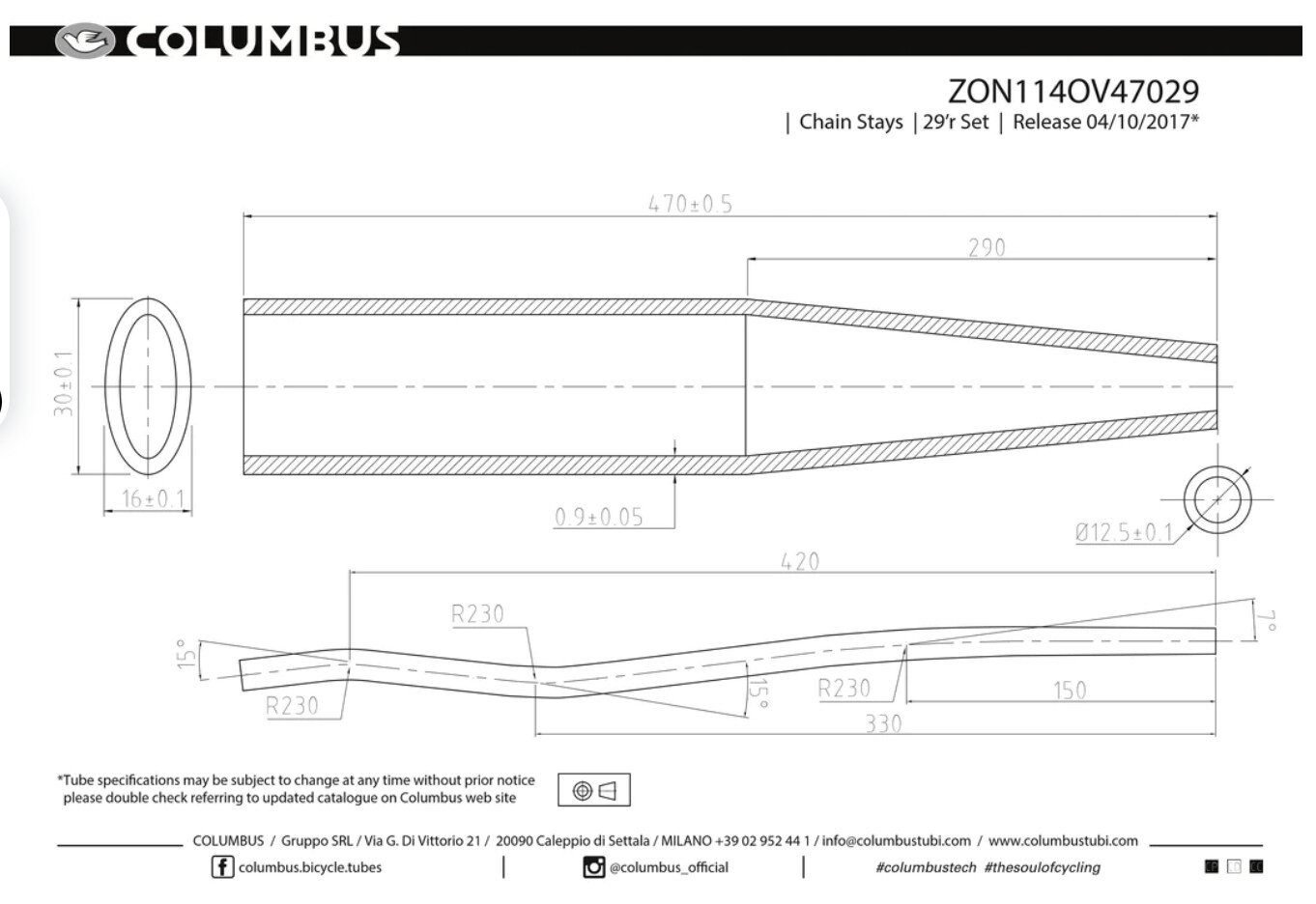
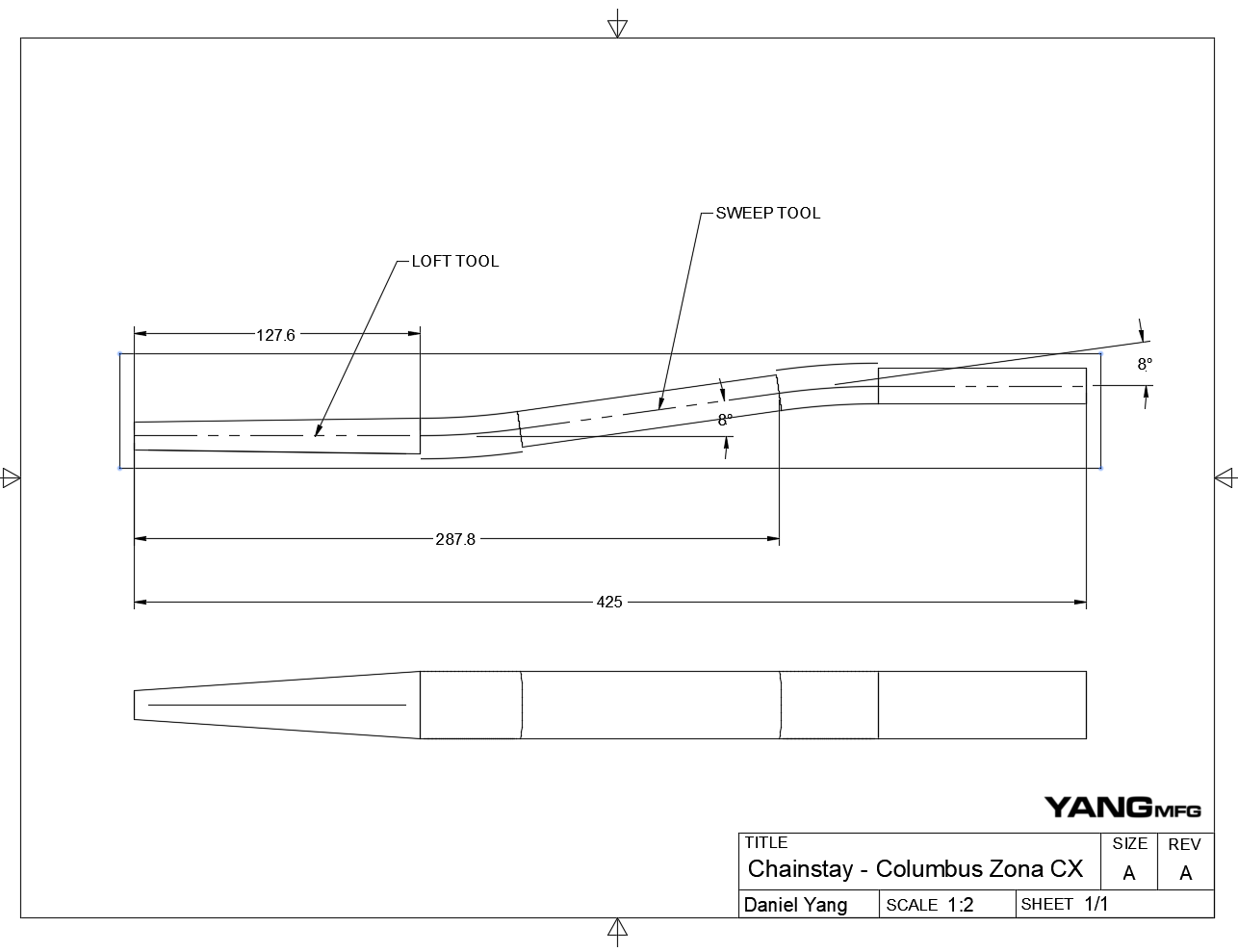
For the chainstay, I prioritize the bend locations rather than the exact shape. Because of this, I sweep an ellipse for the majority of the stay, then use a loft for the last segment:
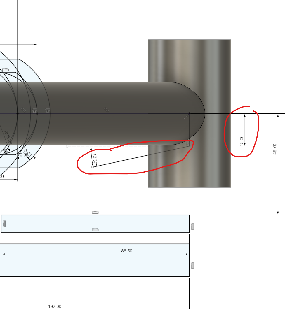
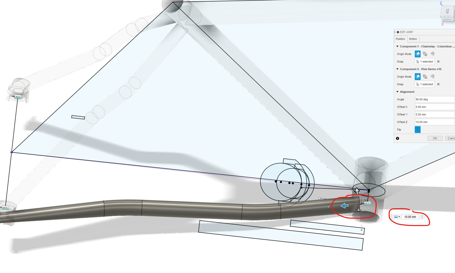
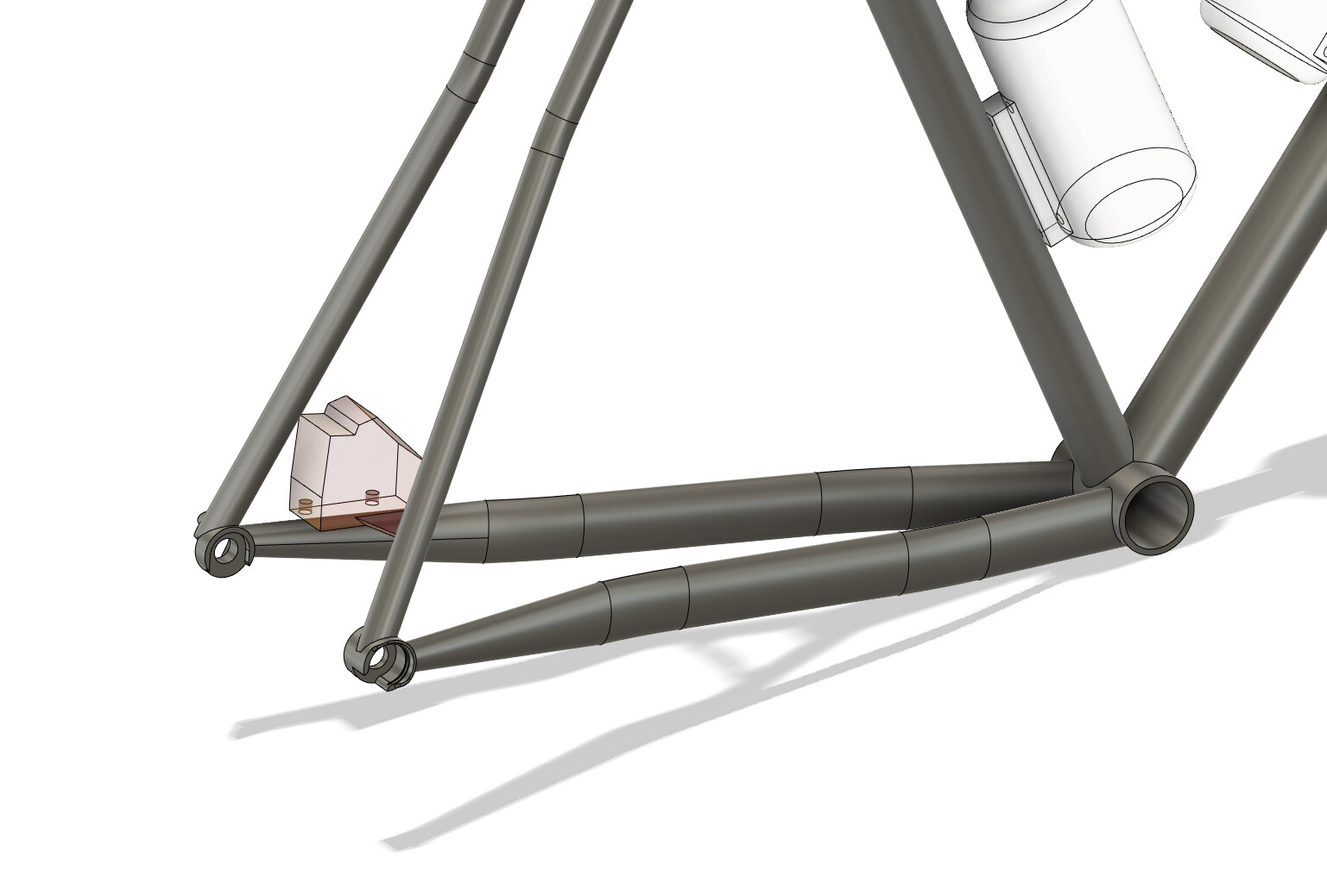
After you finish the joint you will need to iterate the chainstay reference sketch and the joint to:
clear your tire
clear your drivetrain
hit your dropout
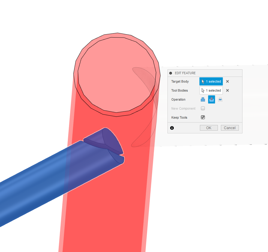
4) Trimming your Chainstay miters
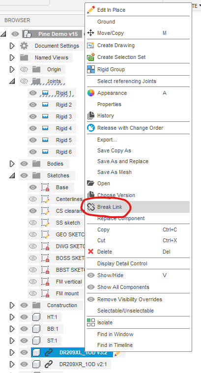
You first need to break the link the original chainstay model. Because we designed the chainstay as a separate model, we can’t modify it in our current assembly:
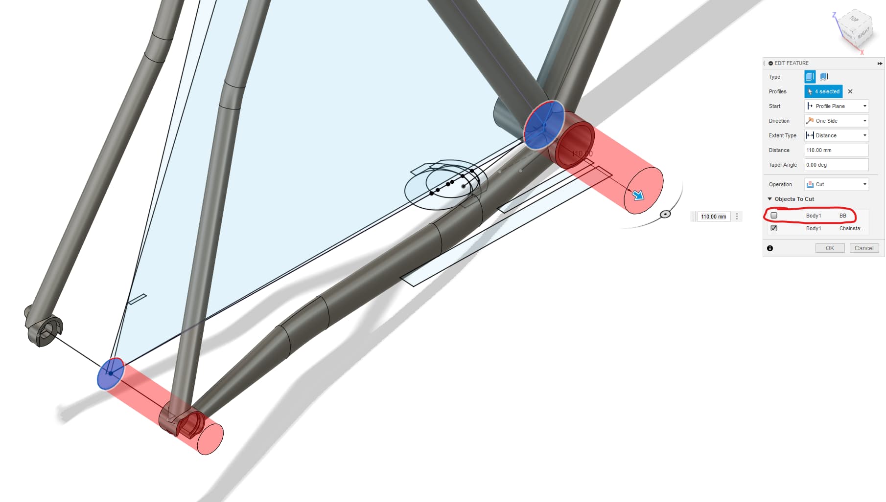
After that, you can use your centerline sketch (if you are following the tutorial verbatum) to miter your chainstay. IMPORTANT make sure you uncheck the things that you don’t want to cut (the bb, dropout, etc…)
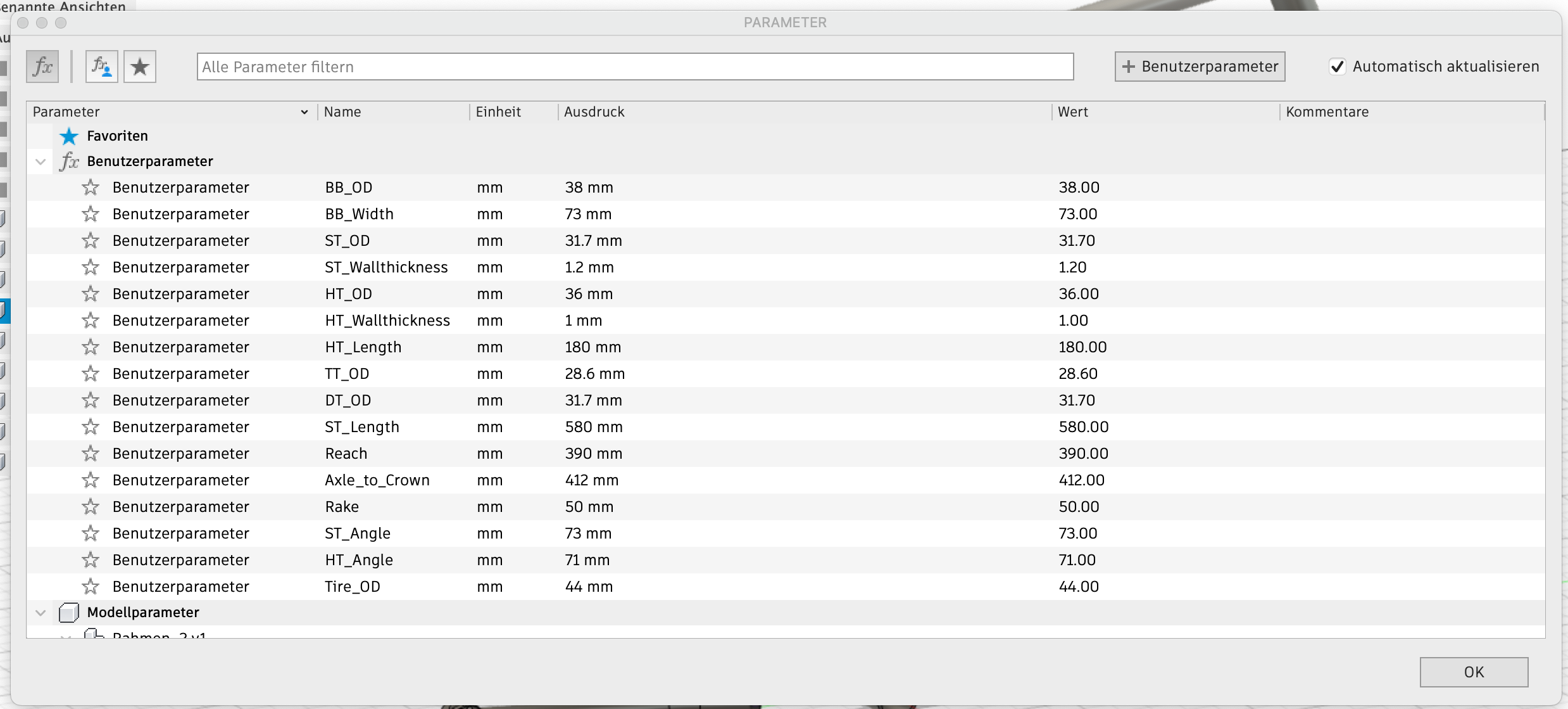
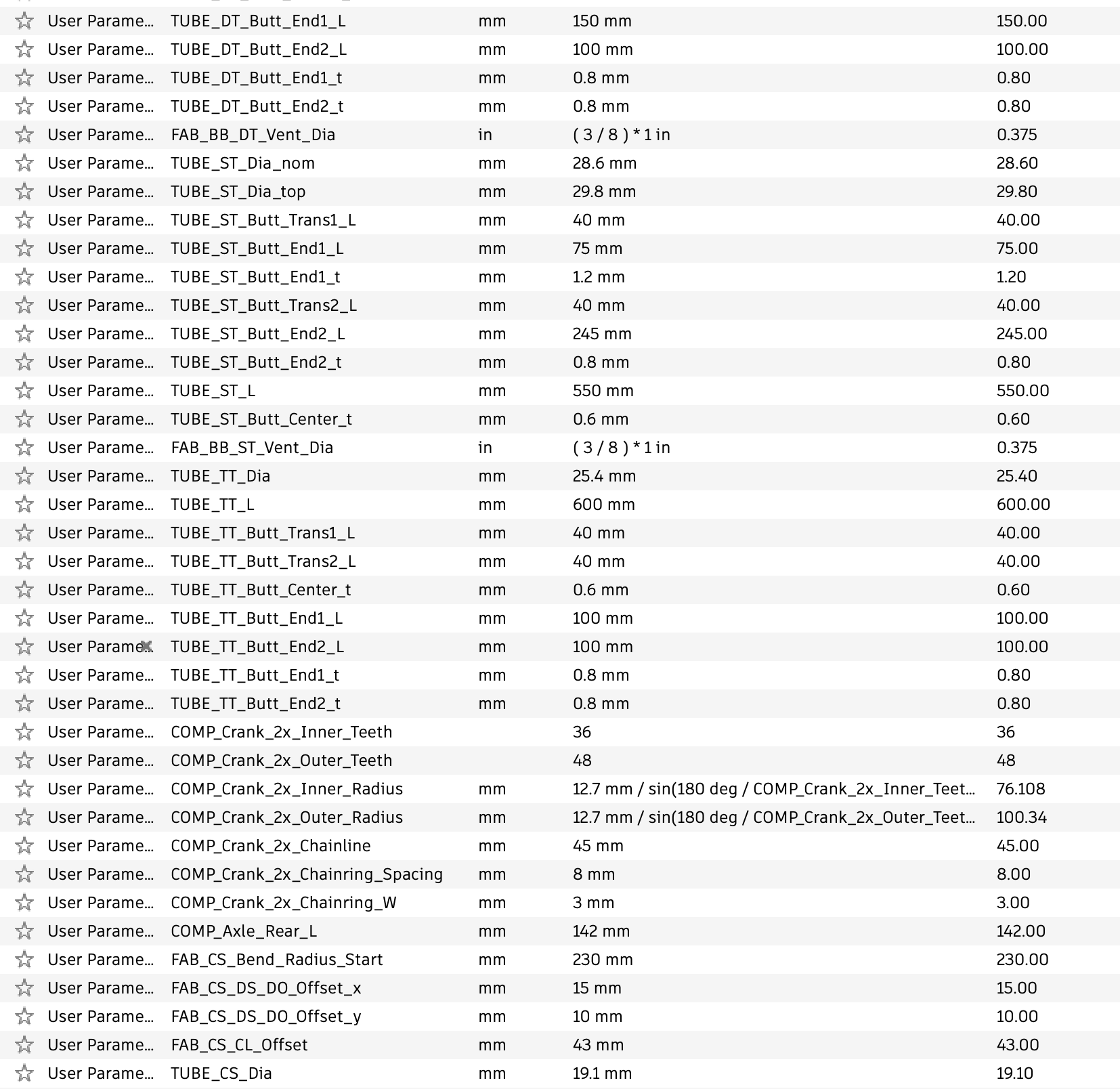
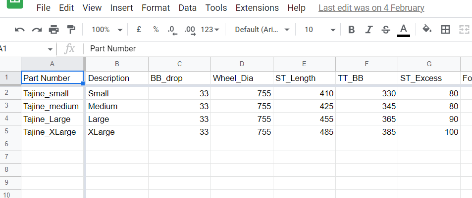
I know some people prefer to put all their dimensions into the parameter table, but I advise against it. It’s much slower, it can break your CAD more easily, and it forces you to visualize a bike as numbers on a chart, not a 3D object.
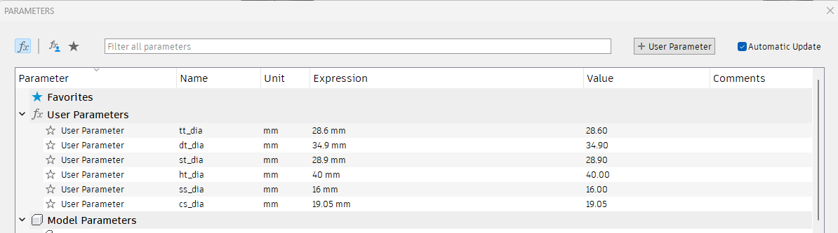
Other tutorials show it, but I don’t agree. In all my models, these are the only parameters I have:
I advise people to try both and come to their own conclusions. I just don’t want people to think that the parameter table is required for a “good cad practice”. I think it’s overemphasized.
Thanks, I wasn’t aware of that. I also re-watched the original modelling video and spotted that I hadn’t added the seattube intersection with the sketch plane to the seatstay sketch. So much to learn!
I’ve attempted this workflow with the sliding dropout and insert DR4139.
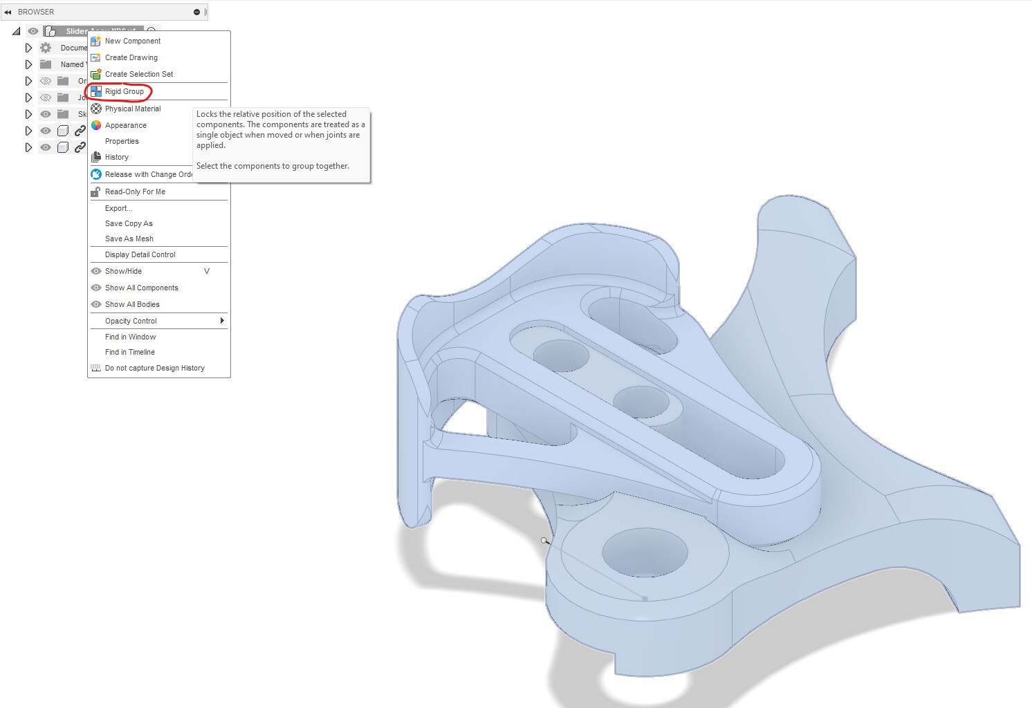
I import step file create a sketch on the insert face and save the file. When I drag it into my model, my reference sketch line is visible but when I attempt to create the joint in my model, only my sketch line moves. The insert, DO, and sketch line are not all one body. I’ve attempted to use the combine function with no success.
What am I doing wrong? I tried using the DO in your how to and end up with the same result, the sketch line joins but doesn’t bring the DO with it.
I think you need to right-click your dropout and slider assembly in the design tree on the left, and select “Rigid Group”. That will lock the parts together.
wanted to add a bit to this topic You also mentioned in the budget frame jig thread that the parameter table can make your model go bananas because you update it bit by bit…
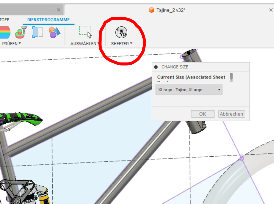
I might have found a solution for that, it’s an external script that can be installed into fusion and makes it sync with a google spreadsheet. It is called “sheeter” and its main functionality is deriving variants of the same object (different sizes of the same frame model in our world), which is also really useful! So you can change the numbers in the spreadsheet and then click the sync button and if it’s your lucky day it hasn’t messed up the model too badly
Really appreciate PMW including the STEP files as well as a proper drawing for their parts. Have found it an extremely useful resource in my latest builds.
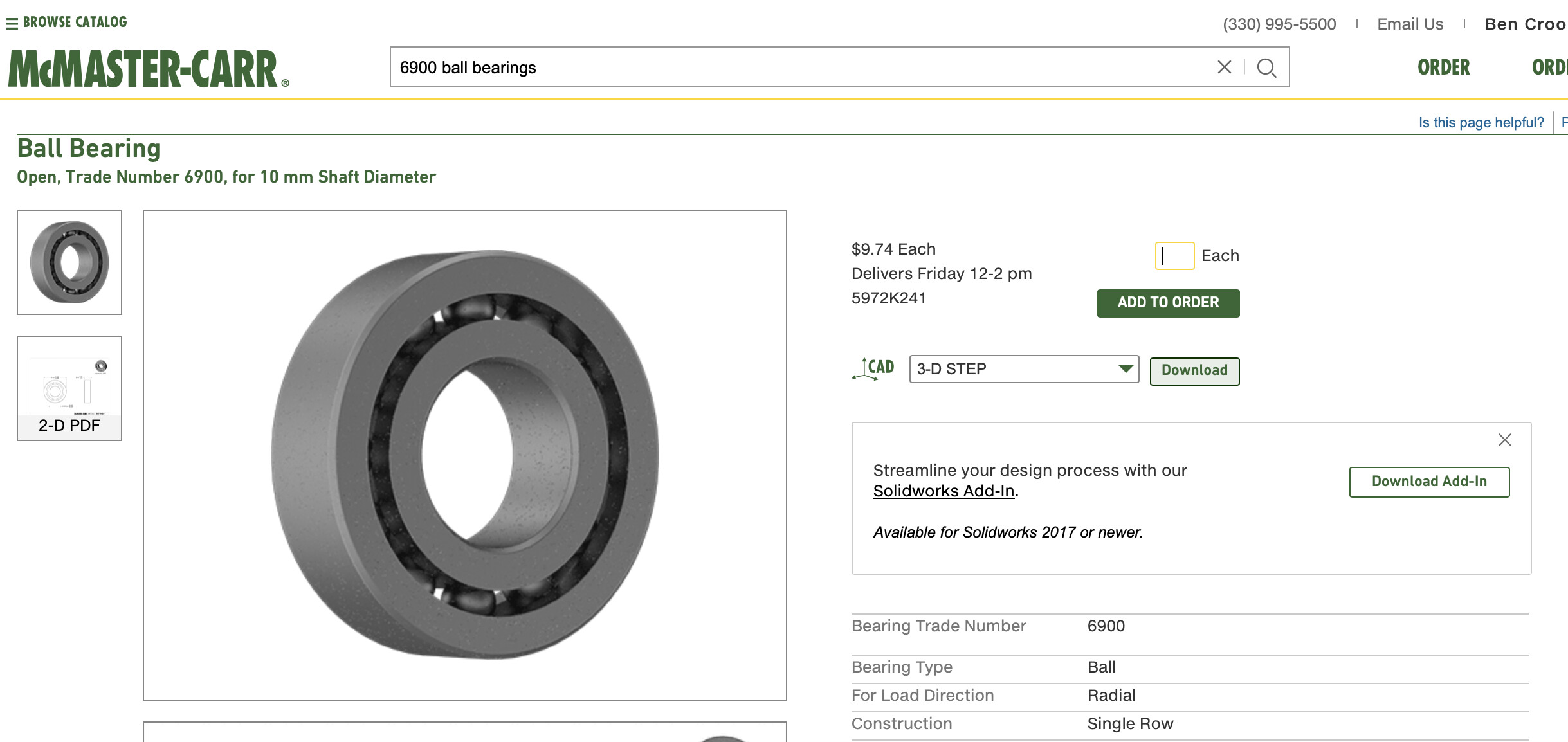
I also find McMaster Carr a useful resource when designing in CAD. 3D models in a variety of file formats and detailed drawings for their parts: bolts, bearings, extrusions, and pretty much anything else you might need for hardware. Fusion also has direct plugin for McMaster.
Grabcad has some pretty detailed models of mtb’s that you can steal some of teh parts line chainrings, cranks,chains cassettes, etc. etc, Great for checking real world clearance on a few things…if you trust they are modelled correctly.
I was just going to say that when I started reading your comment… Things are often modeled for product design purposes, so the goal is to just see how things aesthetically blend together. A millimeter here and there is not so important in this world…
Yeah definitely, though I found one model that was very detailed and all the critical clearance dimensions checked out. So I use these part models to help with checking a few things. Planning things like clearance to the chain, I have a slightly higher chainstay line, are nice to do to save klangers during a build.
Wondering if somebody could help resolve my problem.
So I’m pretty new to CAD, I did a bunch of Autodesk tutorials, played around with it by myself and thought I would try Daniel’s tutorials. So far everything went well, I don’t have too much problem following, I kinda understand everything I do, and ran into some hiccups that I managed to figure out and resolve. But now this one I just can’t figure out:
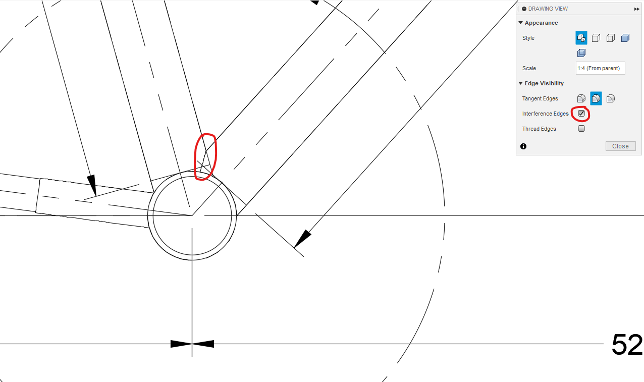
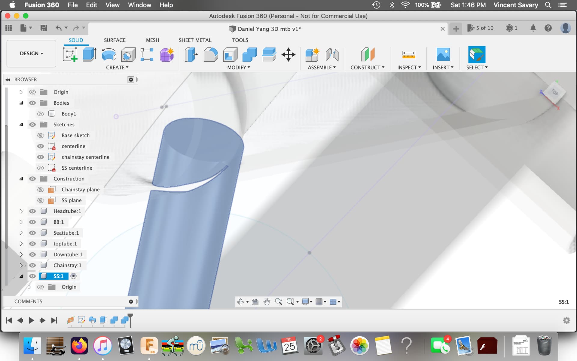
After making the seatstay body and mitering the drop out end (30:33 in the video), when I try to miter the ST end by cutting with the combine tool, it doesn’t create a different body for that little section that needs removing inside the ST. At first I noticed I hadn’t mitered the top tube properly and joined it instead of cutting it and removing the tips, but after correcting that it changed nothing for the SS. I redid the full process for the SS body many times to make sure I wasn’t missing anything, checked the SS centerline sketch many times to make sure I had the right dimensions, the ST is the right diameter, everything seems fine. When zooming in on the SS/ST junction, it kinda looks like the stay’s end is not fully touching the ST, and not making for a full cut.
The only way I managed to make it work is by reducing the SS offset at the ST from 10mm to 8mm. Which, great now it works, but it doesn’t explain why I don’t get the same results. What am I missing? Where did I go wrong?
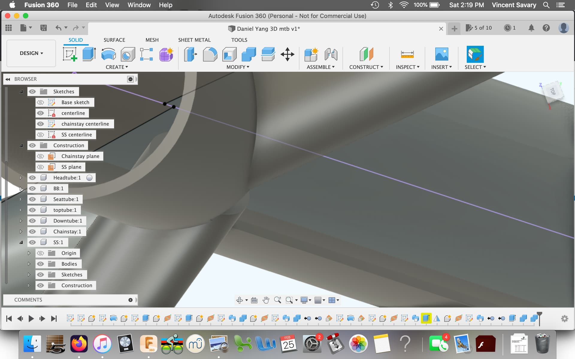
I was unable to replicate the issue. Sometimes Fusion 360 just has a bug in the code. It happens every day to me. Fusion often struggles when two tubes are tangent, or very close to tangent. In numerical method speak, its a “singularity”, when the program is trying to divide by zero, or something really close to zero.
Model the seat tube and SS as solid tubes (not hollow). This is an example of why I prefer to model my tubes solid. It may look werid in CAD, but your 2D drawings will be more robust, and that is what matters more.
Just try re-computing the feature (drag the history timeline backward and forward will recompute)
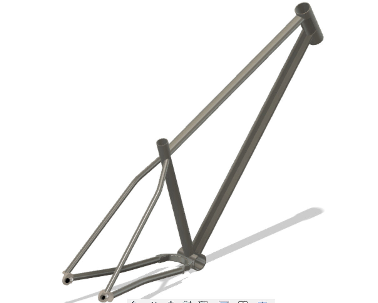
I learned a ton doing this and actually I find it kinda fun to play around with 3D now. To integrate and practice what I had learned I draw a bullmoose that I can adjust every parameter: width, rise, extension, grip angle and head angle. Had to rack my brain a little, but I think I ended up with a good workable model.
Thanks a lot @Daniel_Y , your tutorials are extremely valuable and easy to follow, even for a noob like me. It made CAD much more accessible than I thought it was and straight to the point, since I’m more interested in bike-related stuff.