Here is a new and improved Fusion360 video + tutorial. This took me quite a long time and heartache (I killed my microphone for half the video, so I had to dub over). If you want to show thanks, do the tutorial and post up your results!
Video: make sure you select 1080p resolution!

Forward:
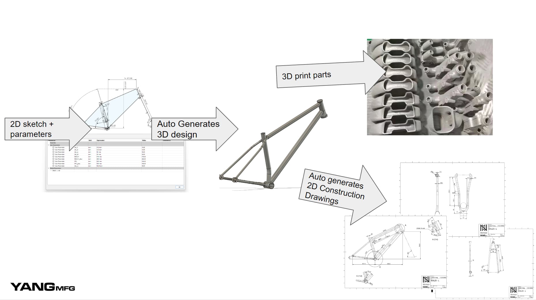
Unlike other “how to draw a frame in F360” CAD tutorials, this one parallels real-world fabrication workflows. This is what @Neuhaus_Metalworks and I used to make over 100 mountain bike frames. Completing this tutorial is the first step toward creating 2D construction drawings. Once you have mastered both, you will have a fully digital design workflow!
Although the video is less than 40min, I expect it to take a beginner much longer (3-4hrs). I split the tutorial and forum thread into manageable chunks. You may find it useful to replay each step and flip back and forth between the video and this guide.
There are many ways to CAD a frame. This tutorial is a simplified version of my workflow, where I purposefully omit more complex geometries and features. I encourage you to follow the tutorial verbatim, then go back to applying custom geometry or fancier workflows!
Good luck, have fun!
Step 0: Get your ducks in a row (do this before the video!)

Download Parts:
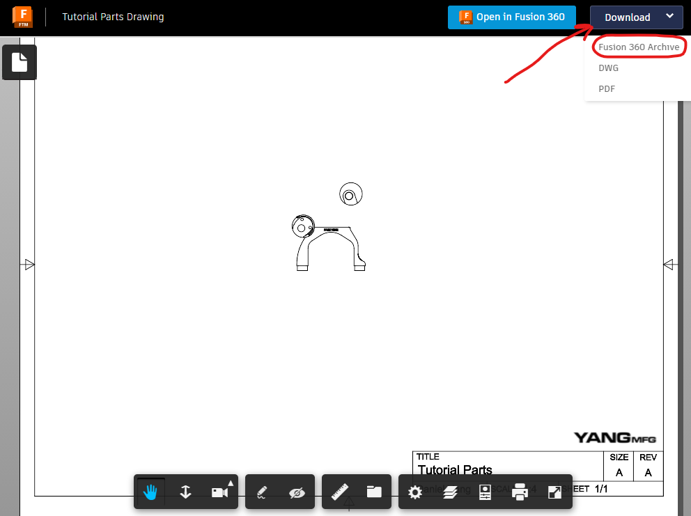
Fusion360 drawing method (preferred!):
- click Fusion360 Link: parts
- download > fusion360 Archive > enter in email
- downloading the drawing archive will download all the parts with it!
Forum Files:
Dropout+1p5+NDS.f3d (171.2 KB)
Dropout+1p5+DS.f3d (152.2 KB)
Yoke+DUMMY.f3d (300.3 KB)
Download finished model:
Fusion 360 link: Finished Model
This is a completed model and drawing. If you get stuck, you can reverse engineer this model to un-stuck yourself.
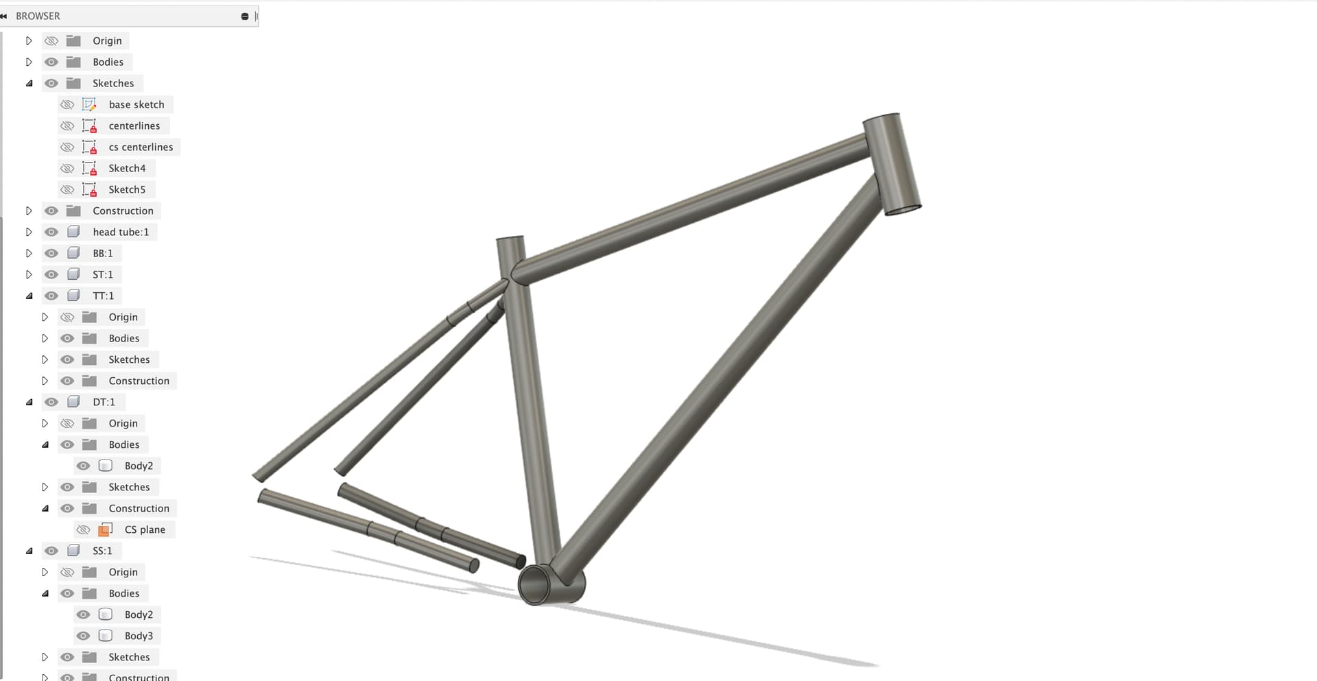
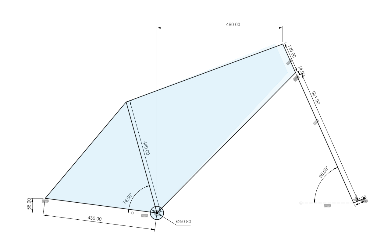
Step 1 - Base sketch 01:07
Tools used:
- basic sketching
- sketch constraints
Comments:
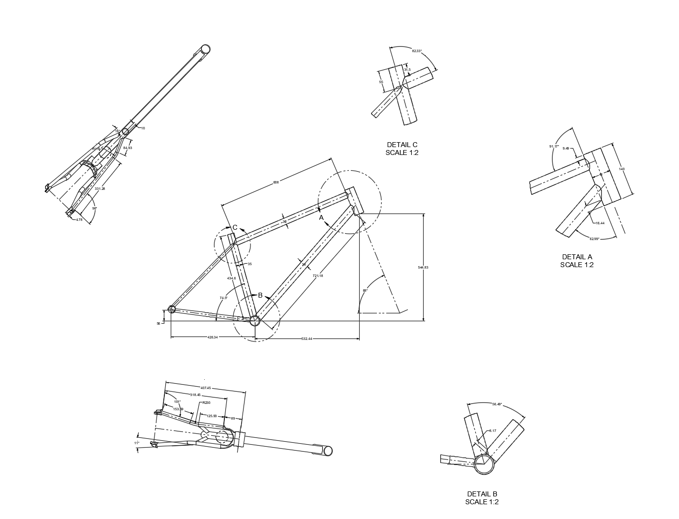
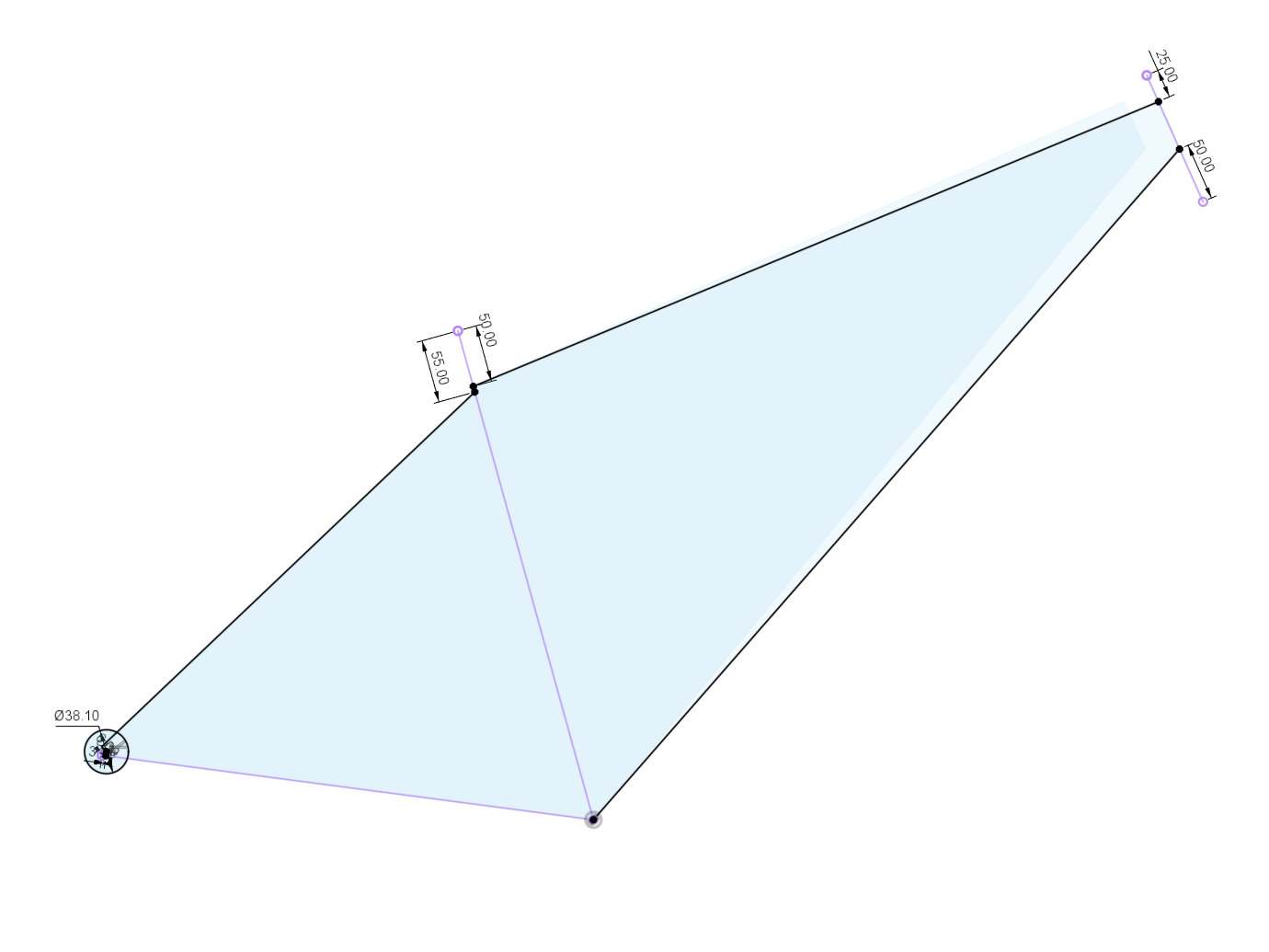
The base sketch contains the fundamental 2D geometry of our bike. We will base the entire CAD off this sketch. If you build your model correctly, when you edit the base sketch, your entire 3D CAD will update as well as your 2D construction drawings (tutorial coming soon).
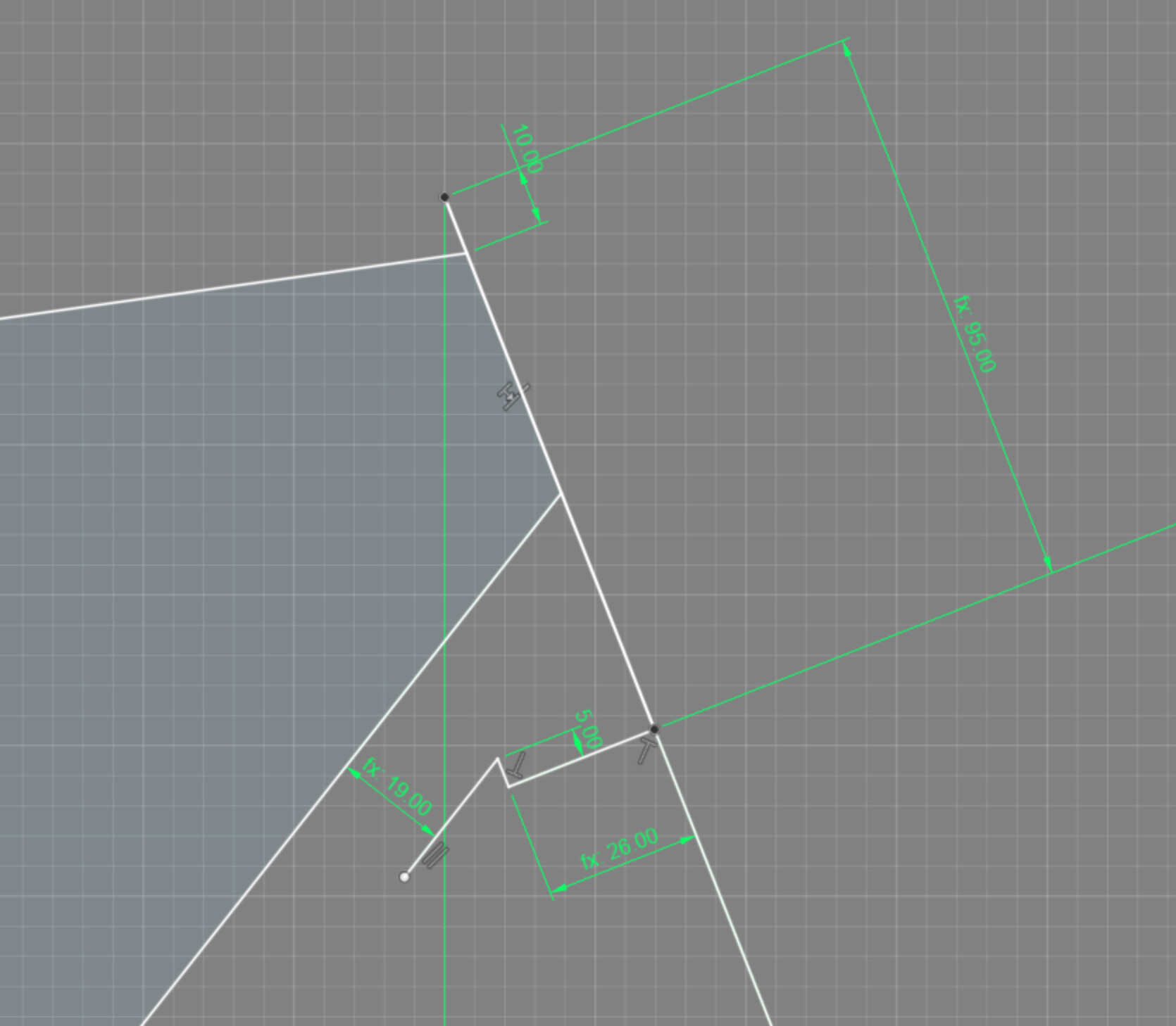
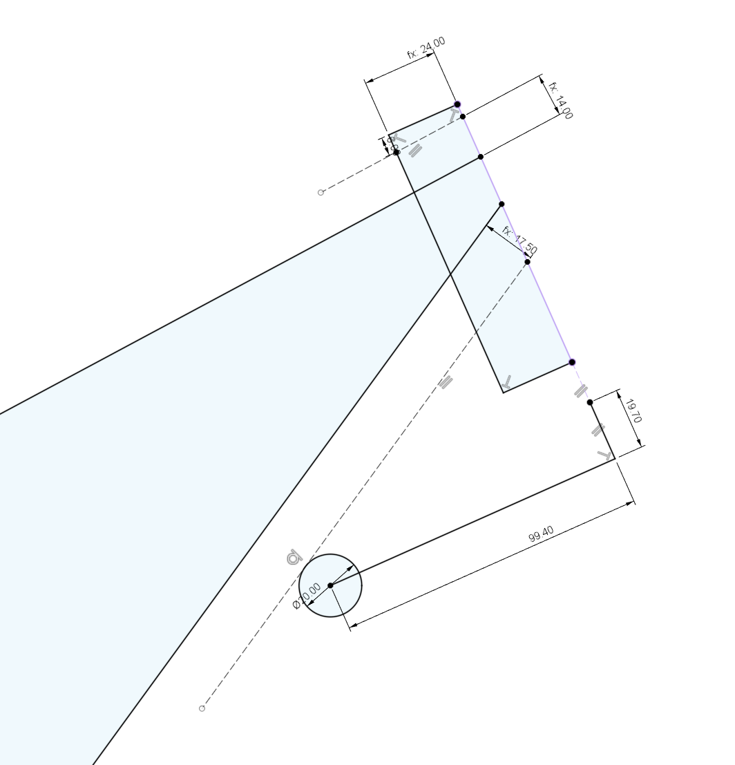
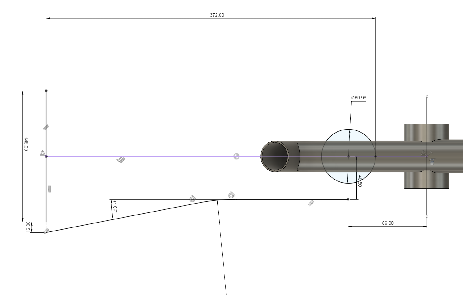
Step 2 - Centerline sketch 04:32
Tools used:
- Projecting geometry
- sketch constraints
Comments:
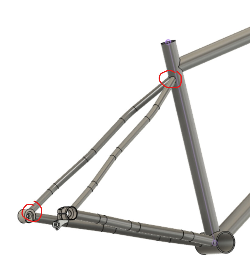
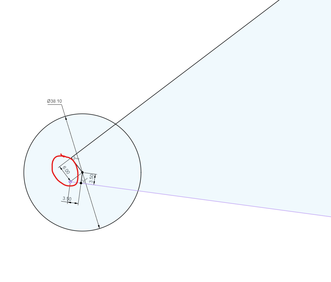
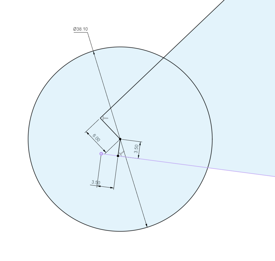
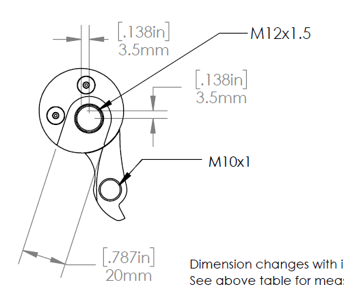
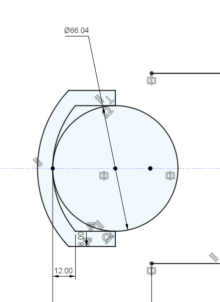
The rear triangle centerline sketch is a bit more complicated due to the non-conccentric paragon 1.5in round dropouts. Concentric dropouts would simplify the drawing quite a bit, however if you follow this tutorial exactly, you will be able to figure it out!
Dropout details:
Step 3 - Draw headtube 08:33
Tools used:
- creating a new component
- toggling sketch visibility
- sketch constraints
Comments:
Don’t forget to create a new component! Don’t forget to go back to your main assembly after you are done modeling your headtube!
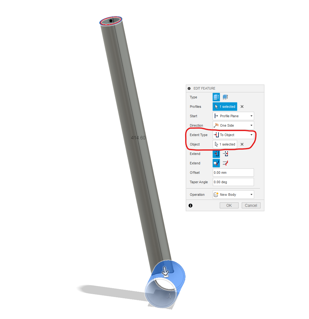
Step 4 - BB ST 12:19
Tools used:
- symmetric extrude
- extrude to object
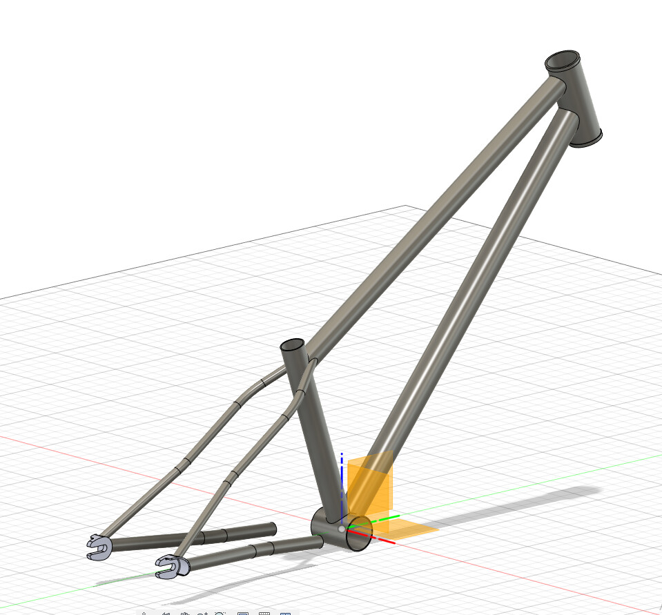
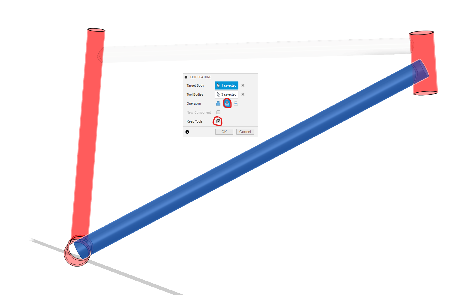
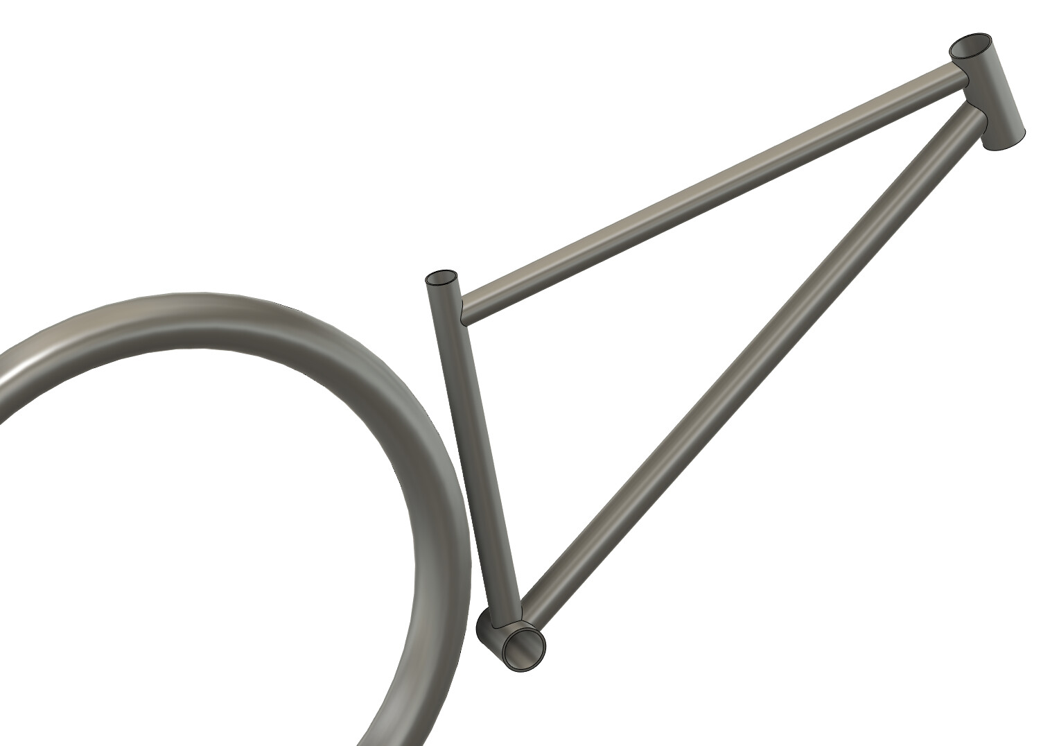
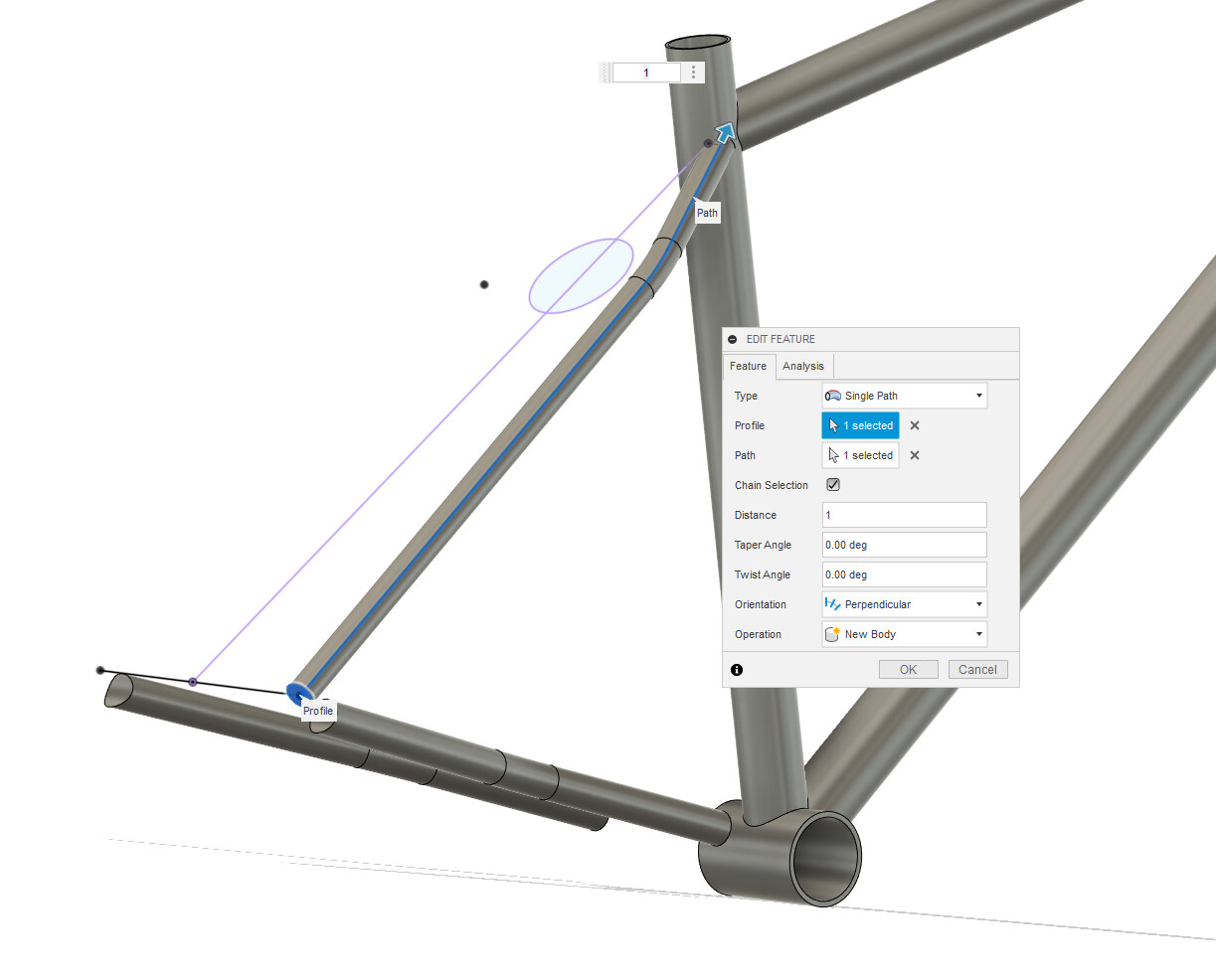
Step 5 - Front triangle 14:47
Tools used:
- construction plane along path
- sweeps
- using combine tool to cut bodies
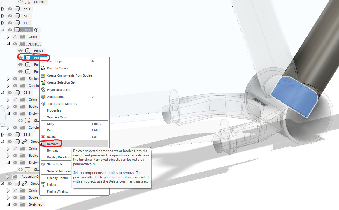
Comments:
In the video, I tried hiding the extra cutoffs to save time. This ended up biting me in the butt when I created the 2D drawings (it automatically displays all hidden bodies). The correct workflow is to right click the body > then remove
Step 6 - CS centerlines 18:49
Tools used:
- construction plane at an angle
- “look at” feature to view normal plane
Comments:
If you are using complex tapered, ovalized, and dimpled chainstays, it may not make sense to time draw “real” chainstays in CAD. Unless you had high confidence in your measurements, it will be more accurate to figure out the chainstay miters in real life.
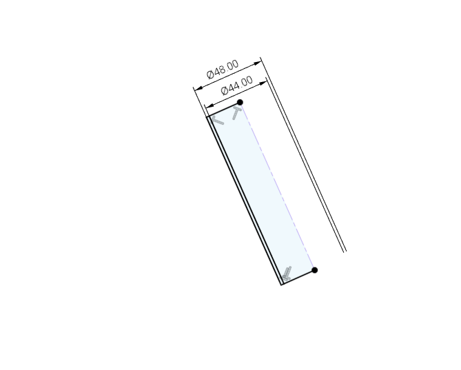
Step 7 - Tire clearance body 22:14
Tools used:
- revolve tool
Comments:
I normally use a more complex tire body with side knobs and 6-8mm of clearance:
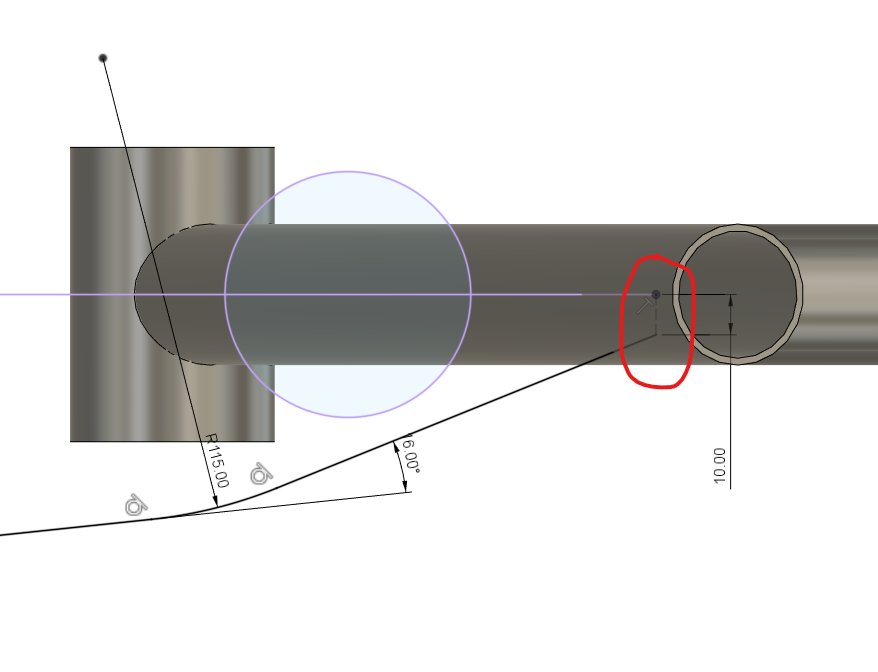
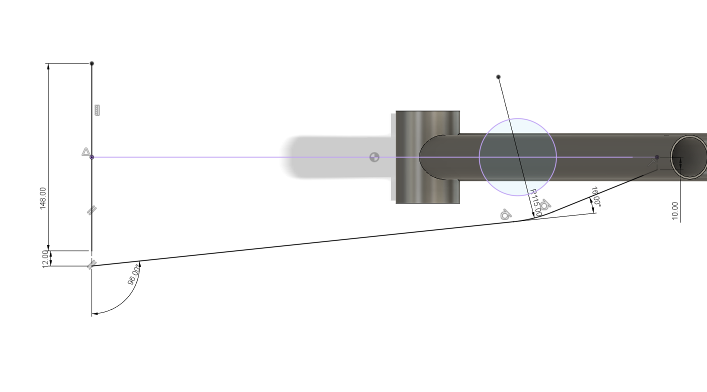
Step 8 - SS centerlines 23:45
Tools used:
- construction plane at an angle
- project > interset geometry
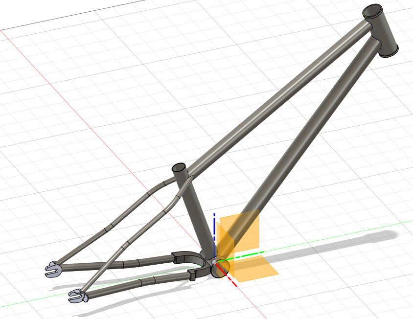
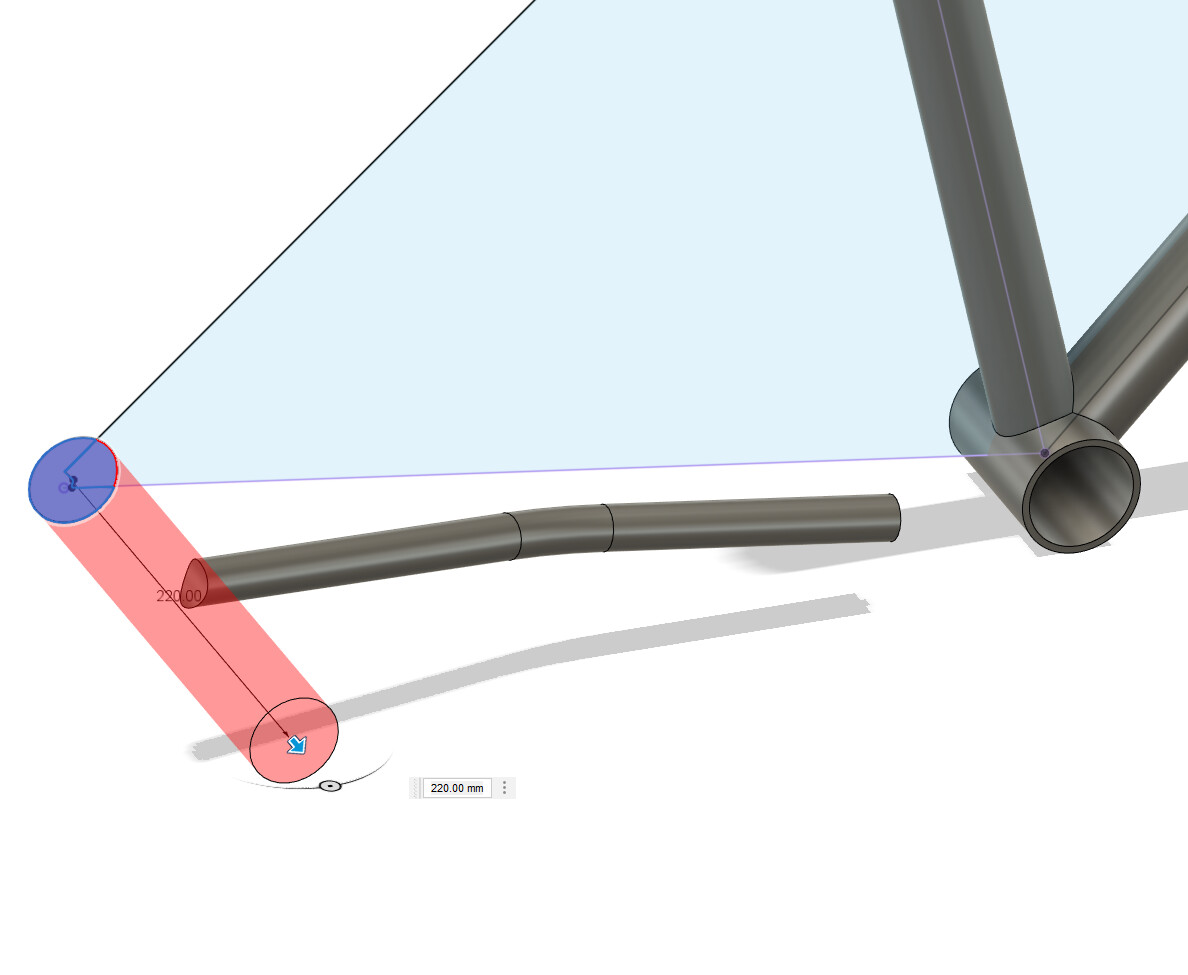
Step 9 - CS body 27:46
Tools used:
- construction plane along path
- sweeps
- cut extrude
Step 10 - SS body 29:36
Tools used:
- construction plane along path
- sweeps
- cut extrude
- using combine tool to cut bodies
Step 11 - Joining the dropouts and yoke 31:20
Tools used:
- adding existing components to an assembly
- joints
- joints to a reference sketch
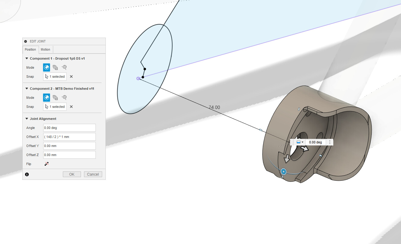
Comments:
There is no easy way around it, joints in fusion360 are very difficult to understand! If you get stuck, download the finished model from above and try to reverse-engineer the joitns. There are some great videos on youtube to help you learn more about joints: https://www.youtube.com/watch?v=Bw08O6XsfDI
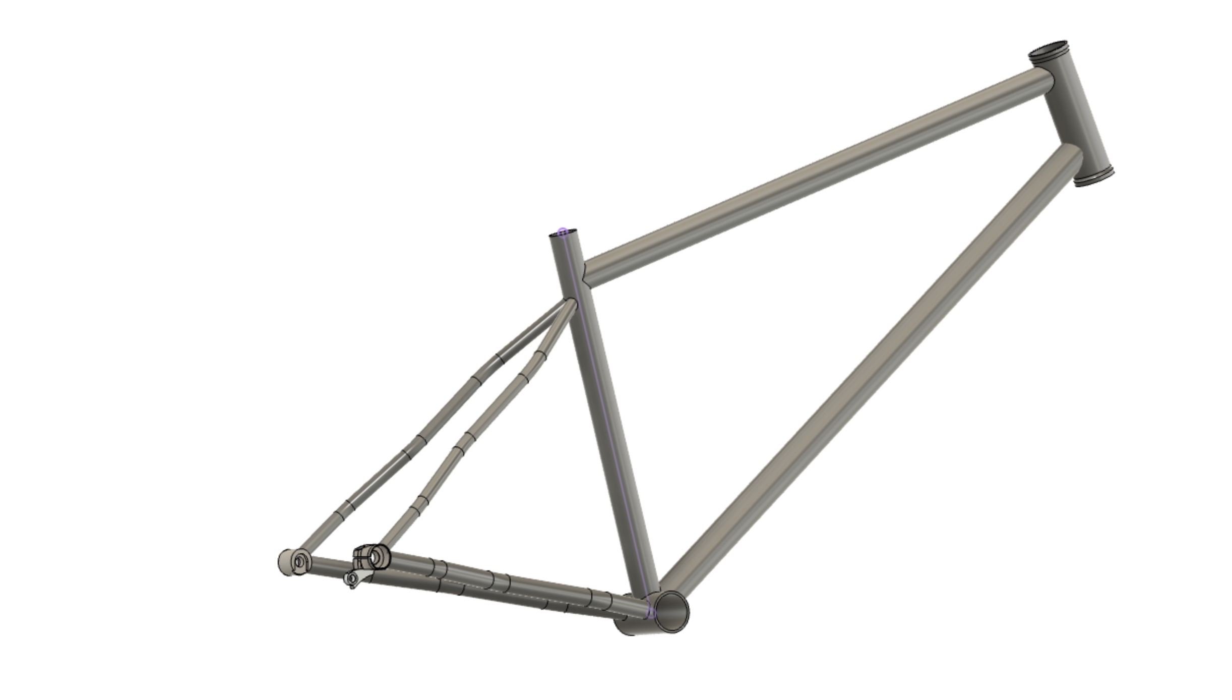
Step 12 - Conclusions 34:59
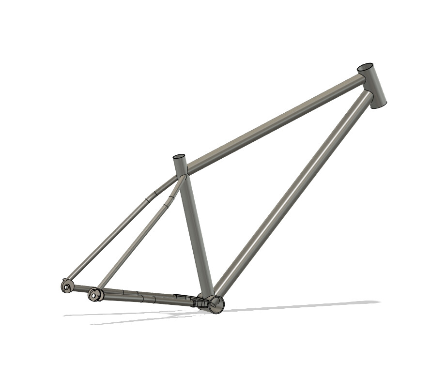
I hope you found this tutorial useful. Feel free to ask questions or leave comments below!
Teaser: 2D drawing tutorial coming soon!