Yeah, the short version is I’m writing a book.
The long version is it’s a super ambitious project that I may never fully put together.
The three main industries where thin-wall tubing is used are Motorsports, Aircraft, and Bicycles. But it’s hard to find any practical information for the home-gamer (or even pros out there). Most Aircraft codes and specs (here in USA) are basically CYA nonsense. You wouldn’t believe the repairs I’ve seen that were certified to fly.
And a lot of the motorsports organizations just have very vague blanket rules that don’t tell the fabricator much.
The goal is to take as much of that information as feasible and put it into a practical guide that Billy Bob the race car driver, or us playing with bikes can use to make better welds in his garage, and more importantly, understand why.
After all, most of these industries (including bicycles) run off of hearsay and “well I did it and it worked!”.
That’s why we have people welding 4130 with Weldmold 880 filler.
But if that never fully materializes, at a minimum I do intend to do some testing on a few things as part of that.
One thing I want to do soon is get some 3D Printed coupons and do some microscopy on them, before and after welding. The college I work at has a nice setup for it already.
Also, I think impact testing (Charpy or Izod) on them would be interesting. I may have to make my Fabrication students build me an Izod testing machine. Hah
Also, that bit is pretty well known if you look at the history of welding aircraft together. It took them many years to adopt TIG welding, because welding with Oxy/Acetylene basically anneals the whole damn thing.
That, and this is pretty general advice you’ll see from different places.
Slowing the cooling rate is of course the goal. That however, gets interesting when you start adding stainless parts to bikes. (Or 3D Printed stainless)
University was in the US, so had access to some AWS databases, but those mostly covered theory and didn’t have much specific information. Transferring out currently, debating on going back to a school in Norway finish or not, but will at least be without academic access for a little while. TWI looks to be kinda pricy, hard to judge the value. I’d love to get to do more of this stuff, but not sure I’d be able to do it how I want through a educational setting.
Nice. Seems like our interests overlap quite a bit. I certainly got frustrated by the information available, and especially how none of it seems to have direct evidence backing. An impact test would be cool to see, wonder what fracture mode it would cause. Its hard to argue against the “I did it and it worked” without a lot of data that says otherwise. I’ve built and broke a fair few bikes with a lot of different types welding settings as well as filler metals, but with all the factors involved I have no way of saying confidently whether any parameter was specifically at fault. This study definitely didn’t fulfil any of my questions, but its at least something to build upon.
These are sort of the general pieces of advice I’m not convinced are sufficient given the trends/possibilities of low heat input with pulsed tig and heat-sinks etc. Anyone know of the source of how this number of wall thickness came about? Surely some level of testing was done.
Yes, I agree. I always say I hate rules of thumb. But, they can be useful of course.
To me, understanding the hows and whys are always more interesting. That way decisions can be made depending on what exactly you’re doing, instead of blanket advice.
But as for where the wall thickness number came from, all I can say is with my experience with AWS and ASME welding codes, I really do feel like the numbers are just pulled from you-know-where sometimes.
But, it does make sense in a way. For a code book, you have to give exact numbers. As an example, the D1.1 Structural Steel code says 32f is the minimum preheat (most of the time). Does that mean at 31f you will have problems? No, of course not. But they chose 32f because it’s a nice round number that’s easy for ironworkers to follow.
I guess that turns into a ‘letter of the law’ vs. ‘spirit of the law’ conversation though.
ah if you were at university in the Uk most have an agreement that gets you acess to literally thousands and thousands of articles and actual industry research into that very topic by some pretty well known industrial companies.
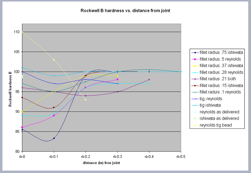
I still need to get up into my attic and look through all my old college papers for that Bontrager study. But I found a summary of his findings posted at framebuilder Bob Brown’s web site: Bob Brown Cycles: analysis
I finally got around to checking out that summary, the data presented from the Bontrager study is certainly interesting, but I have to say his write-up and conclusions following it is not very good. Not to mention the typos and wrong terminology used.
Based of of the chart he made (from Keith Bontrager’s data), we can see the initial hardness of the tubing, the annealing / softening at and near the weld, and then the return to the original hardness or close to it farther away. (I believe the slight increase in hardness we see on some of them could possibly be due to measurement error, statistical probablility, etc. I don’t know what his testing conditions were yet.)
This is exactly what we expect after welding, returning at or close to the annealed state in the weld, and then a gradient through the HAZ back to the unaffected tubing.
I’m gonna have to add this to the list of things I want to test myself. Should be interesting.
But his conclusion is that super-fast and small weld beads are the strongest? That’s terrible advice!
Although I must agree that welder skill will always have the most effect. All it takes is one discontinuity in the right (wrong) spot to propagate a failure.
I’ll also say that if you’re trying to make a race-bike that is as strong as possible (but might fail catastrophically halfway through) then this may be good advice for you.
But most of us would rather have a bike that lasts 20 years instead of one that runs the ragged edge of material performance.
Also, the very next section talks about metal fatigue. He certainly talked about how hardness roughly equals tensile strength, but made no mention of how ductility (or lack thereof) and fatigue failures can work together.
Question for the metallurgy folks, as I am simply a “dumb welder”.
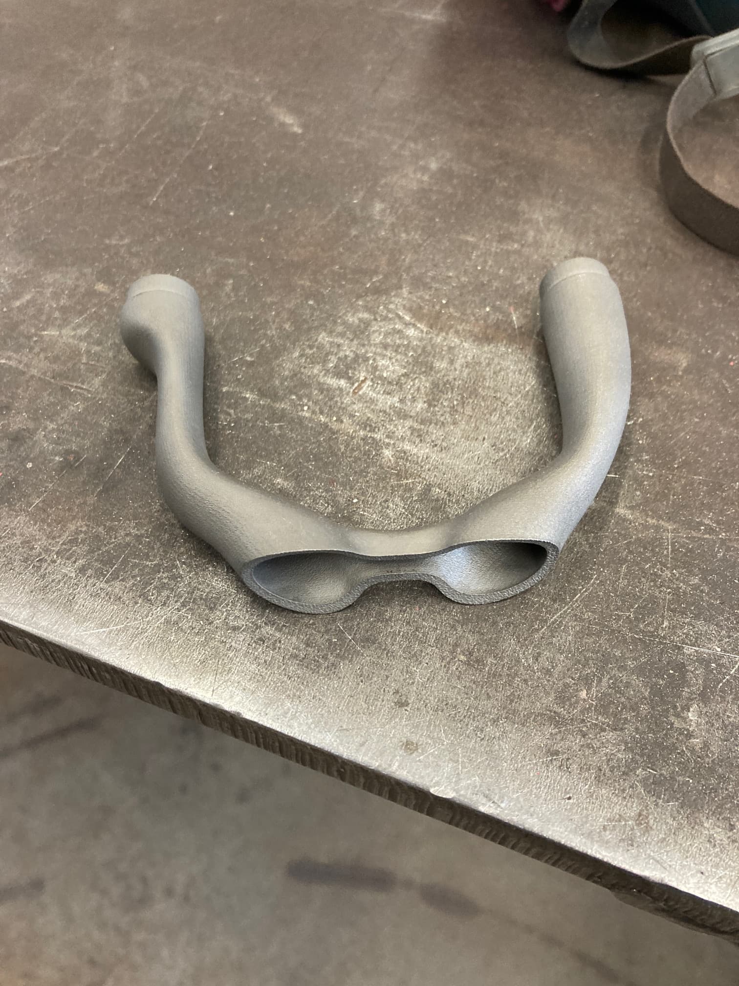
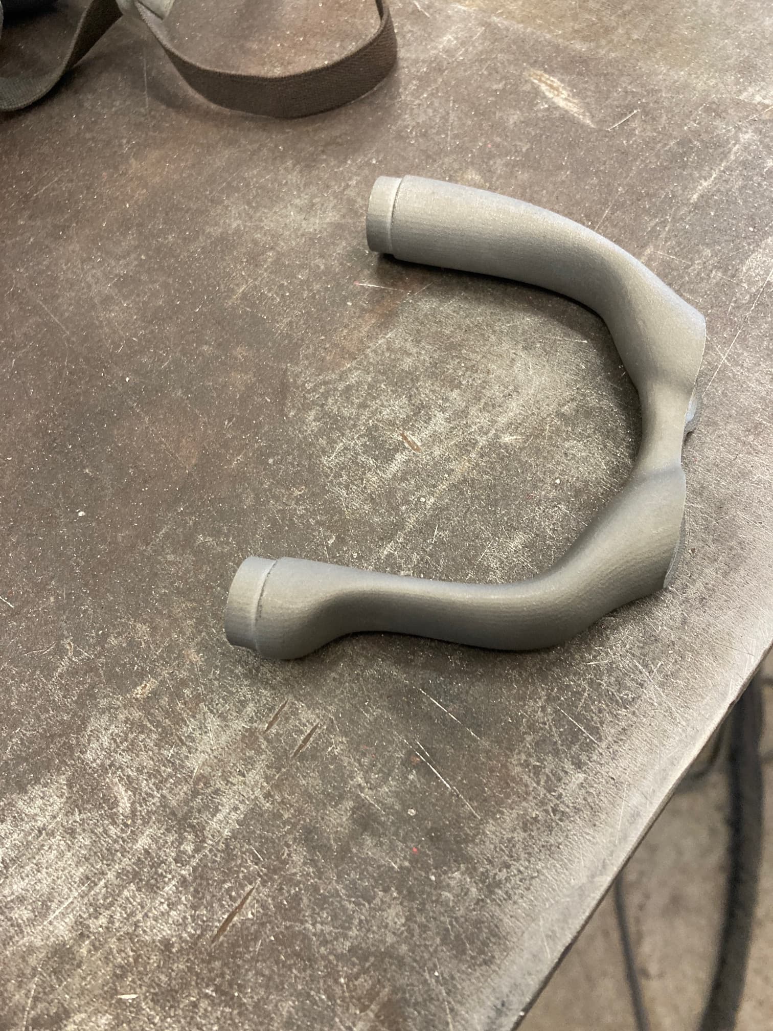
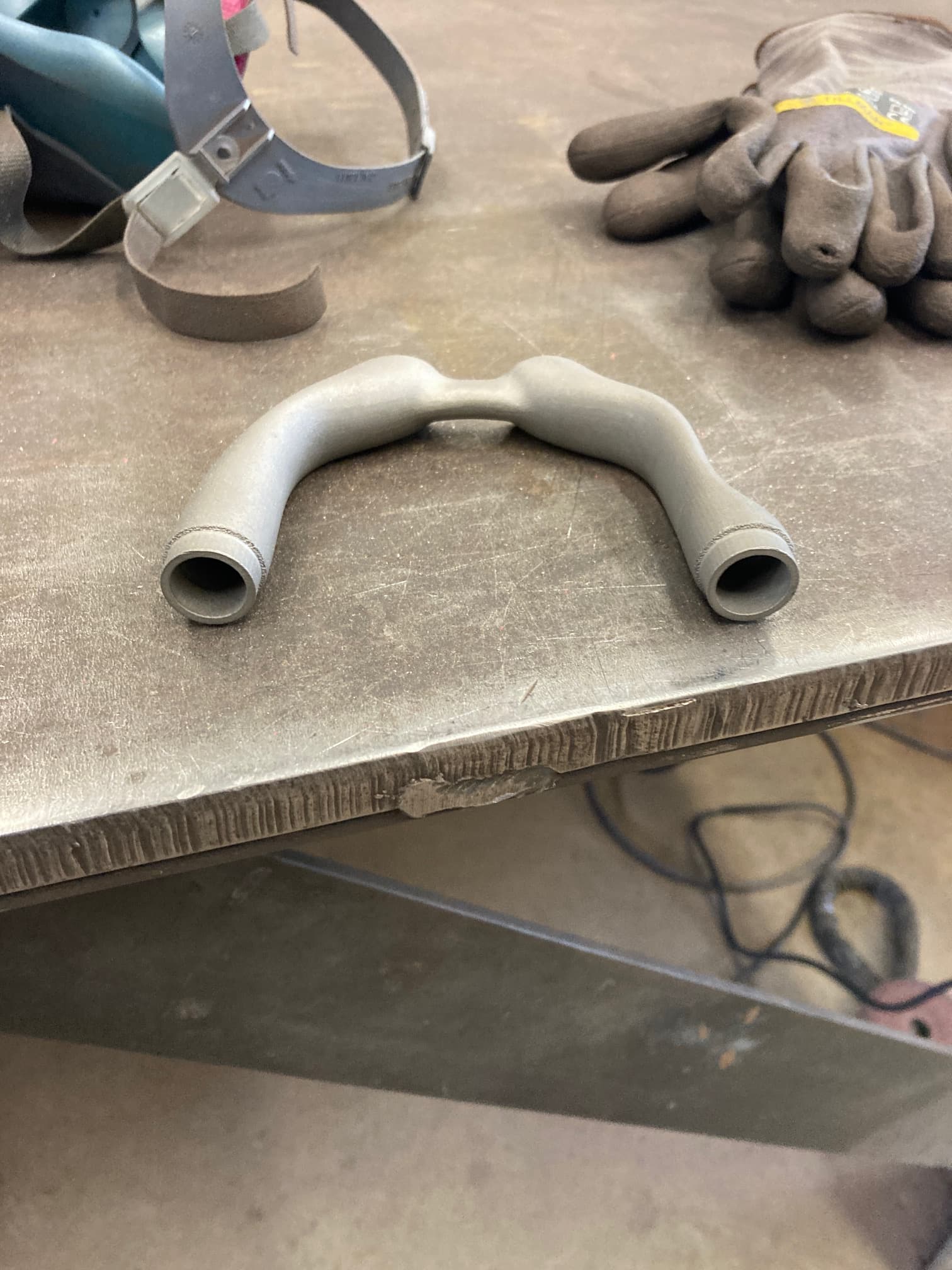
I had a yoke printed with the help of @Daniel_Y and I am getting close to being ready to weld it into something usable. I believe the part is 316 and I am wondering if simply using some ER70s2 will be adequate. I am sure it will weld fine, but I am unsure if this going to alarm anyone more informed on metallurgical properties of welding 4130 to stainless.
Also, I am not opposed to having this be an experiment of sorts as long as it doesn’t raise immediate concerns with folks with more real world experience than me. Thanks, and I appreciate any input!
I use ER312 on all of our welded 316 parts, which is specifically for joining stainless to mild steel. Weldmold 880 is also a good choice as it is essentially er312, but it is more expensive and I don’t like way it wets out as much as er312. I have a bunch of both on hand and would be happy to send a few pieces of each for the cost of shipping.
I will see if the LWS has some er312, if not I will reach out. I have heard the weldmold is essentially the same as er312, good to know it has some different characteristics while welding. Thank you for the input @Neuhaus_Metalworks
I can add some notes here, as much of the reason I pursued this was to question with this exact opinion (faster/less heat input = better). My post here does not necessarily do a great job of being clear, but many things ended without results so sort of the nature of the game.
The primary question is: where exactly (in sort of micro-m to mm respect to the weld bead) are frames failing. In my experience of around 10 frames/frame sections cracking, they 100% of the time fail immediately at the edge of the weld. They also, from visual inspection, as well as in the nature of their cracking, have very little plastic failure mode (i.e. stretching of the metal before failure). The failures I have had that have had plastic failure have not cracked (though maybe if I had continued to ride), and have occurred on the scale of 2-5 mm away from the edge of the weld.
Though relationship between hardness and tensile strength are well established, it is the correlation to frame failure that is questioned. The softest (and therefore weakest) point, is some ways away from the joint. Optimizing towards the lowest possible heat input leads to a narrower band of this weakest point, but is only valid for failures in this region. Where all my crack failures have occurred the hardness is almost at its highest (and therefore highest tensile strength), which necessitates another reason for failing. To this cause I did not get a chance to check for further (somewhat why I posted here to potentially continue the testing), but some reasoning to a remedy based on the following is possible:
It is generally accepted that in higher carbon (and carbon equivalent) steels, a preheat is necessary to avoid brittle weld/weld area by allowing slower cooling. If brittle failure is the issue (as mine seem to be), it makes sense to avoid going in the opposite direction.
Stress concentration due to geometry likely plays the major roll here. To help this, avoiding cooling stress in the weld pool as much as possible (which adds to the applied stress if in equal direction) seems like a good thing. Weld metal residual stress was still a relevant issue for research when I was doing this report, so there are probably many more things that contribute, but we can reason from experience of the welding community that some welding techniques likely cause more than others. Tacking or welding crack sensitive metals shows that the rate of cooling of the weld pool is critical. Therefore, forcing the weld pool to cool as quickly as possible (with pulsed welding for example) it seems likely that we are increasing the chance of brittle failure. The shape of the weld bead is also relevant, so the amount of filler wire can have an affect also.
This is becoming an old post at this point, and in my mind many things could be updated. That being said, since this was written my experience and experimentation/cracking of bikes one thing is becoming clear: if the joint has geometry that forces a sharp increase in stiffness of a member that flexes continually, the immediately-next-to-the-weld failure will occur regardless of weld technique/heat input. So though I am (and others are likely as well) still very interested in the micro and macro nature of welding and its effect on bike frames, it should be clear that I do not think it is the main reason for my frames failing like this.
Essentially, welding 4130 as fast and as low heat input as possible runs the risk of hardening the material as you weld it.
It’s the same concept as heating up metal red-hot, and then quenching (like we do for knifes and such during heat treating).
Granted, the risk is relatively low with thin-wall tubing, as the heat simply saturates the whole area regardless, but it’s still not best practice to weld as quickly as possible with a pulser, heat sink, etc. This can create un-predictable areas of hardened material that can also lead to failure.
Harder metal does indeed mean stronger, but also more brittle. Brittle failures can be unpredictable and often scary / catastrophic, while ductile failures are more often than not found before the tubing is in two pieces.
Ductility and hardness must also be considered in context, as ductility is often the most important when fatigue is concerned. And regardless of road or MTB, bicycle frames have a ton of fatigue involved from regular use.
I didnt read it the most thoroughly, but I believe the study is for brazing rather than welding. The smaller fillets (and implicitly faster brazed) retains more hardness.