Welded joint failures and metallurgy

This seems like as good a place as any to share a project I did during my MSE education, related to TIG welding 4130. We weren’t able to achieve data on the failure mode I was aiming for, but it did show some insightful trends that are very relevant. I’ve seen some links to Bontrager’s study in the 80s that I don’t think has the data to back some of the conclusions and makes some harmful simplifications. It seems that maybe some of the precautions from this paper have maintained influence to this day, but it seems to me like with 40 more years of experience the steel frame community could achieve more thorough understanding. There is also likely more research out there that I dont know about. Either way, I’d love to start a discussion on the experience with failures that happen, and then hopefully build upon the knowledge about them with further testing such as this and for example the fatigue testing being done by @Equinox.

Some more thorough information on the metallurgical background of some of the terms and phenomenon might be needed to understand this fully, but if that is of interest I can do that in a different post. I’ll link to the full paper we wrote, but I’ll add a word of precaution that it was a group project and some sections (especially introduction) have some faulty information. That being said, a full method, results and conclusion will be have to read there to avoid a ridiculously long post here.

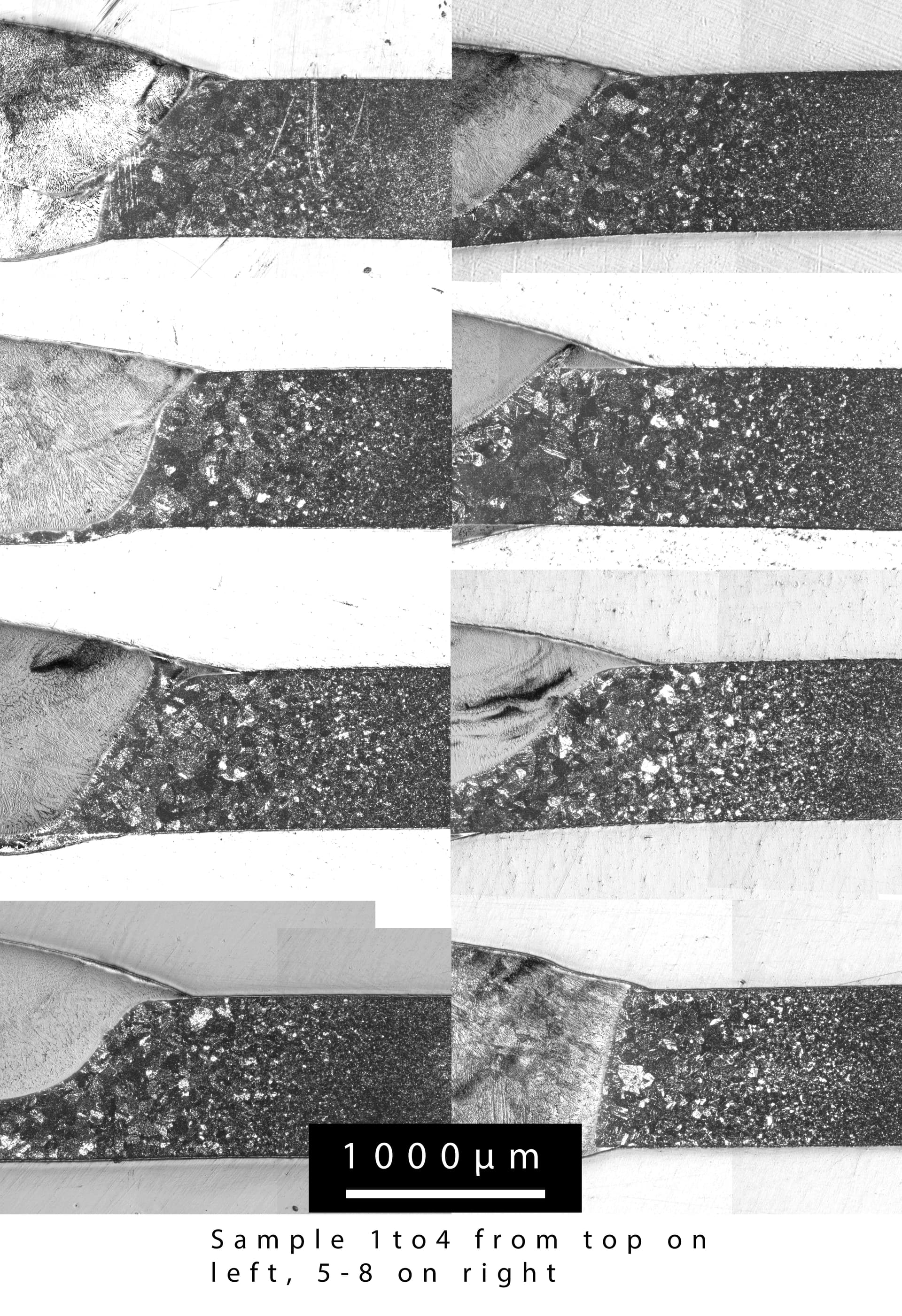
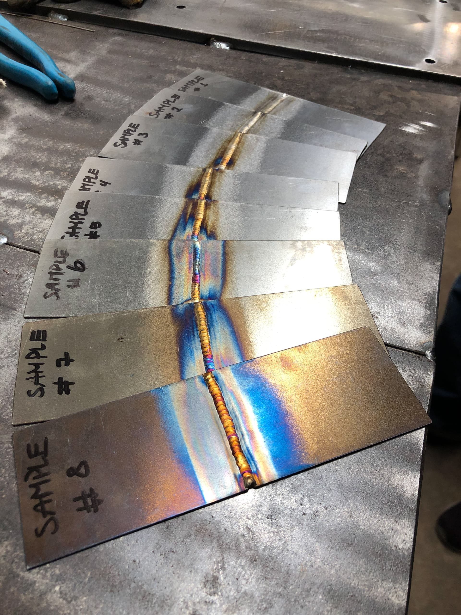
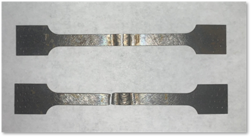
The aim: To study the effect of heat input on fracture resistance. This was done by testing welds made under a range of preheat conditions (with a cooled or heated jig) to change the cooling rate. It’s visual effect on the welds is seen in the picture below. Due to the different preheats, the only way to achieve similar welds was to approximate weld size and travel speed by foot pedal. A range of 0-275C preheats was done, with 8 samples total spread in between. 312 filler was used, which made the etching portion of the project fruitless. Dog Bones were EDM cut and tensile tested, and the remaining faces were mounted for etching and hardness testing. The hardness and tensile testing results are shown here. All dogbones broke ~2mm away from the toe of the weld, except for two samples that did not have complete fusion and fractured through the middle. No welds fractured “at the toe”, which was the failure mode I was aiming to gather data on. I think a fatigue testing scenario with a stiff, notched tubing sample would have to be used to get that.

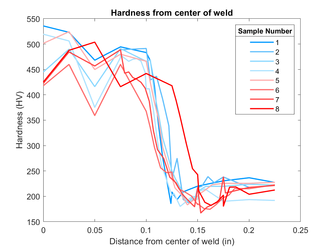
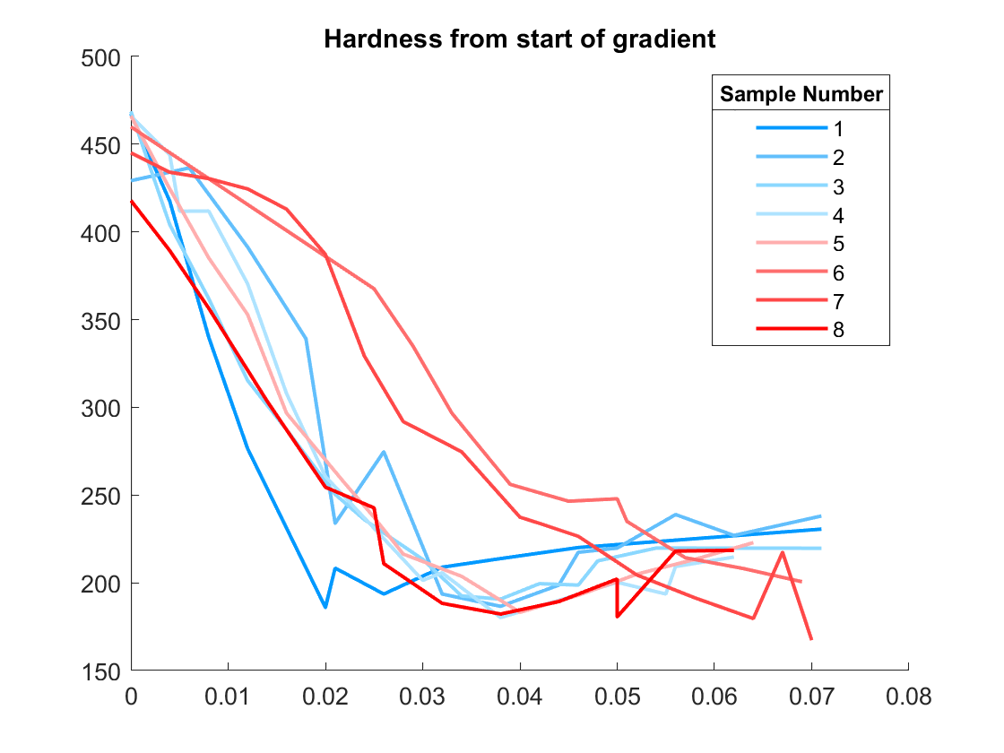
The Hardness testing was done on the Vickers micro scale, with a micrometer table so increments of 3x indentation widths could be made. The “interesting” location is right at the change between hard and back to base metal. This change in hardness starts beyond the weld metal, substantially into the HAZ. A full graph and zoomed in graph is shown below to highlight the trend. For all graphs, blue is the lowest preheat, and red is the highest, and the range between. From this its seen that the highest hardness and lowest hardness are similar in magnitude, but the gradient decreases with increasing preheat.

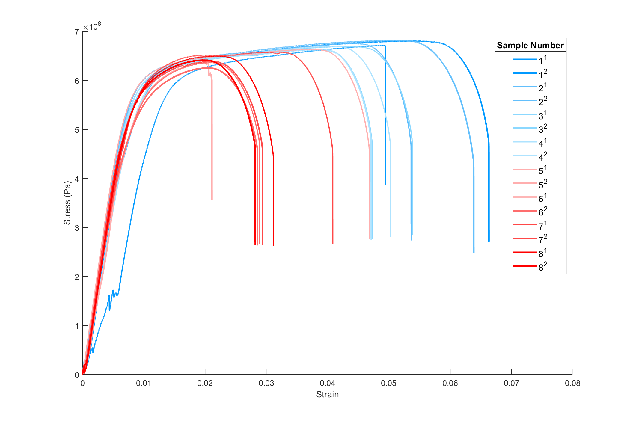
Tensile testing was done on two samples from each weld. The two samples that broke in the middle are the ones with abrupt endings, and the first sample slipped in the jaws so its start is shifted. Increasing preheat strongly correlates with decrease in toughness. All samples still yielded at the “same” stress, and all plastically deformed outside of the weld.

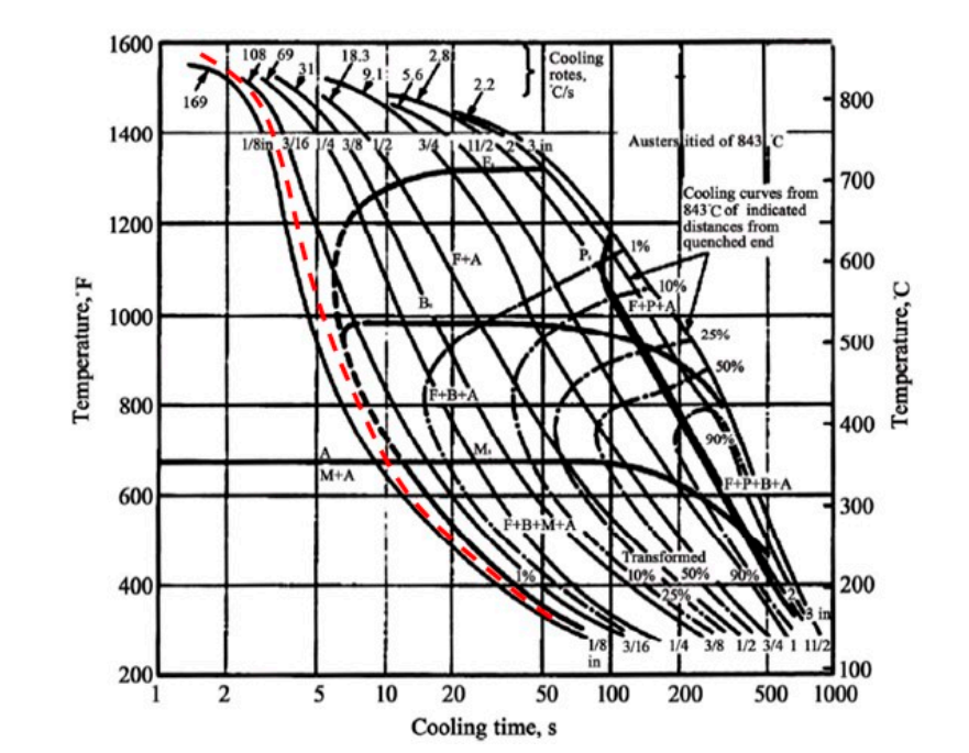
These results are quite in line with what I expected of a “normal” plastic fracture mode. Grain size strengthening is a dominant mechanism in normalized tubing, which must share a significant overlap with the fancy “air hardening” tubing that is sold. These grains increase in size in the HAZ, decreasing the strength and causing the plastic deformation and failure to occur there. The harder fusion and weld metal zones most likely have cooling rates quick enough or shrinking stress high enough (or combination) to cause martensitic phase formation, as they are significantly higher than the underlying metal. The 312 filler also solidifies hard, but more likely due to precipitation of carbides as it remains single phase austenite. The martensite phase is famously brittle, and is what is warned about when welding thicker 4130, and is shown in the CCT diagram below. Unfortunately, very little insight could be gathered from those in “academia” with higher credentials, though I have on two occasions been told by metals professors that aluminum is not weldable unless by friction welding, so I suppose that would have been too much to ask for. From literature review on the subject it is clear that fracture mechanics in welding is difficult to conclusively determine. Therefore, a qualitative, experimental type of direction, with some ground rules in metallurgy, seems like the most valuable way to go about increasing the knowledge.

If you made it this far, thank you. The importance of this is dependent on which type of fracture is the bottleneck in reality. I have broken a greater number of frames by the “at the toe” fracture mode, where there is no plastic deformation. I have had a frame yield at the same location to the samples in this project, but not to fracture before I saw it and stopped riding the frame. I have only been making frames for 3 years, and I have only been riding one of them for more than a year consecutively as I have been through many design iterations, so though I certainly put my bike through more than significant stresses, I don’t have the basis for high-cycle fatigue influence that others on here likely do. So any data on where, how and from what circumstance joint fractures have happened, as well as any other insight into this nature would be a great way to contribute to a common better consensus.

I think this pertains especially to the “the less heat input the better” type of rule of thumb that I was definitely guided by in the introductory part of my frame building journey. Due to the competing phenomenon, grain size increasing vs brittle phase, it seems to me an optimized strategy would lead to a compromise, weighted by whichever failure mode is more common in practice.

Please let me know if something is overly confusing or lacking, and I look forward to the conversation.

EDIT: link to paper: 4130 Weld Project.docx - Google Docs

16 Likes

I think I have a copy of that Bontrager study somewhere, I can try to find/dig it up if there’s interest. Or is it available online?

-Jim G

1 Like

@ isakleivsson, This is interesting, thanks for posting it!
I work in the welding field, and am currently working on a deep dive project into some of the stuff around welding thin-wall 4130 tubing.
When I click the link to the paper, it says I don’t have permission? Don’t know if that’s on your end or mine, I’ve never seen that for a google link.

and @jimg I’d definitely be interested in that Bontrager study if there’s a copy somewhere!

Sorry, changed the viewing permission now!

I saw this link in the gusset fatigue thread: https://bulgier.net/Pics/Bike/Articles/Bike_Tech/vol_4_'85/bicycling_bike_tech_vol_4_2.pdf

Unless there are more this is probably it, on page 10

Thanks for sharing this, it was an interesting read.

The results were a bit counterintuitive to what I expected. I assumed a heat soak at 400c would have let the grains chill out as the weld cooled. Instead, it seemed to have the opposite effect.

A few questions:

  • did you do a control sample w/o any welds to test the nominal stress and strain?
  • Why do you think the dogbone failed so far away from the weld?
  • To me, it looked like there was some thinning and shrinking close to weld bead. Do you think that had some effect on the “true stress and strain”?

The magical properties of “heat treated” “air hardened” 4130 have always caused me to raise eyebrows, so I’m glad you are putting some assumptions to the test.

It was unclear to me whether tubes were annealed, normalized, or heat treated. In a conversation with Anthony at Fairing, he told me the non-heat treated tubes are work hardened:

Regarding the 31.8x.8/.5/.8-600mm tubes, the mother-tubes (blank tubes) will also reflect the hardness. For example, to make this tube the factory has to start with the next biggest size, 34.9mm, and draw down to spec (I forgot how many passes but at least two because for each butt). BUT if 34.9mm tube is not available or a shortage, they would use the next biggest size, 38.1mm. Using a bigger OD will make the tube a little harder because of more drawing down needed to get to spec. And yes, they have to anneal tubes prior to cold drawing to spec.

Not to add another variable to the chaos, but maybe the bike tubes fail closer to the joint because they have a higher hardness/angry grain structure from the cold work of butting?

A couple things here I think I need to add some background info to. I can do a bit of a intro to metallurgy that would have more info if anyone is interested. Gives light to some differences in the types of tubing we use, and how some of the strength values that are listed might not be as comparable as they seem.

The grain size of the microstructure in a normalized sample is directly dependent on how much time it spends at elevated (not melting) temperature. So the grain size problem near the weld is the metal that has not melted, but has been at some elevated temperature for some time. The higher the temp the faster it happens, so it really only affects a small area just beyond that of the melted metal, and definitely not in the size range you see visually with discoloration. In the first hardness plot, it is the part at 0.15 away from the center of the weld where the hardness is lowest. You can see this somewhat in the picture here, though the base metal is over-etched. But just to sum up, the higher preheats have “worse” or coarser microstructure in this area due to spending more time at elevated temps (unfortunately its hard to see due to the etching level required to etch the stainless filler)

We did not, unfortunately, test a control sample. That being said, it can be compared to known values for 4130, as stress is normalized to cross-sectional area of the sample. It was compared in the report, where yield stress, ultimate stress were nearly equal, but the standard value showed much higher elongation, 25% vs the highest achieved 6.5% here. The elongation could be affected somewhat by our dogbone geometry, but the trend of decreasing elongation with increasing weld heat input carries, so it makes sense.

The dogbone fails in the coarse grain area, where it is weakened by the heat. Just to be clear, by “at the toe” I mean immediately at the toe, where as these fail ~2mm from the toe.

The tensile test shown here is referred to as engineering stress and strain, where the force is divided by the original cross section. This is usually the standard, though true stress and strain is sometimes used, and the instantaneous cross section has to be accounted for. The thinning is referred to as necking, and is a key way in determining whether something fails with a brittle or ductile fracture mode. The ductile mode absorbs a lot of energy and in a sense “gives a warning” before failing, which in most terms is preferable.

Work hardening is another strengthening mechanism, on the same line as grain size. That is interesting about the tubing sizing, I wasn’t aware they used the same blank without annealing steps in between. The state of the microstructure before welding likely doesn’t really have much effect on the microstructure in the fusion zone (where the base metal melts), since this “resets” any microstructure, but in the non-melted HAZ it probably does. This is something I want to in the future look more into, so hopefully I can get set up to be able to do some micrography to be able to do that.

3 Likes

Really interesting experiment. Thanks for posting the pre-print. I’m assuming you’re submitting it for publication?

What journal are you planning to submit to?

Interesting stuff here. I like your other roof drop testing procedure too!

2 Likes

This was merely a semester project in an undergrad lab class of last year, no aim of publication. It’d be cool to be able to submit something like this to a journal, but to be fair this study was pretty limited in time and I’d say needed quite a bit more work to allow conclusions beyond just extrapolations.

3 Likes

The ol’ roof drop standard

2 Likes

Fair 'nuff.

I asked as I was hoping you did a literature review regarding the topic… haha for my benefit of course!

Although, even small undergrad experiments can be important (and publishable) if the results are novel and interesting :slight_smile:

I mean… graphene was ‘discovered’ with some tape.

2 Likes

Definitely, and thanks! It would have been interesting to gather more data on it. Hoping to do more on it in the future, I still have some hypothesis on it that I’d love to test.

Reg literature review. We definitely did a little, but found little as the number of relevant papers is low. There are some 4130 pipe-welding papers, some robot tig and laser welding, but nothing thin-walled or fatigue related. I might have another go at finding more. On that topic, does anyone know of any more bike specific papers like the one Bontrager did? I hadnt found that one before so maybe our lit-review just wasnt very good haha

2 Likes

I’m not sure I understood did you look at anything aircraft related ? Theres a lot of reference material I’ve read a fair few papers from the likes of the EAA there are entire books written on the subject of airframe fabrication and the mathematics behind thin wall high cyclical fatigue plenty of aircraft out there use 4130 for their airframes and plenty of them are aerobatic seeing high load cases I believed the new pitts is rated up to 12 g also if you go looking for more examples engine mounts for a lot of these small aircraft are often 4130 fabrications and again have codes and standards and nearly a century of calculations and testing behind the methods used

Roll cages and chassis building in race , rally , drag cars all have literally reams and reams of information out there on our side of the pond at least the Americans do things slightly differently , but you can still glean a whole host of useful information from the last 50 odd years of development etc they tend to have much bigger budgets than any bicycle company left building steel bikes these days to do the research.

Is just one example for bikes

1 Like

The type of literature I mean (and didn’t make any explanation of, lol my bad) is more of the purely materials science realm. My aim is primarily in the weld solidification parameters, which will vary greatly depending on material and joint configuration/wall thickness, as well as welding procedure. Sort of a correlation examination between the phase configuration in the HAZ vs its ability to both withstand peak stress and fatigue, specifically for 4130. This is where I mean there is little information. The MSE world is a little niche, and in many cases it seems experience with successful welding procedure is most of the time good enough, as the structure (and the analysis of them like the papers you linked) is probably a more important factor. That being said I’d be surprised if there isn’t quite a bit of MSE information out there I haven’t looked well enough for, like the aerospace and motorsport world as you mention.

I apologize for the probably confusing aim of this work. Maybe some notes on what I want to apply it to would help.

Due to the varying TIG welding settings available, with low speed/high speed pulse with hugely varying background/peak settings, as well as just travel speed etc, it is possible and feasible for most people to achieve either a very low or high level of heat input to achieve the “same” visual looking weld bead, not including color. Especially if heat sinks are included. My hypothesis is that due to the susceptibility of 4130 to martensitic phase formation, these procedures and a “as little color / heat input as possible” goal is detrimentally affecting the joint strength.

The way I see achieving this is really only through being able to replicate brittle fracture in testing different weld settings. Maybe something @Equinox wants to do? If not, also some microstructural analysis (of which we were completely lacking in this paper due to the etching issue) would probably provide insight too. Optical microscopes don’t seem that expensive so this is probably something I’ll aim to do on my own in the future.

Am I wrong in thinking you only did rupture testing, no fatigue? Bike frames fail in fatigue. You see people bending the crap out of frames to show their joining is good and it really doesn’t mean much. Oh, good, I can hit a bump on one of your bikes and not die. It’s not clear to me how rupture testing gives me any information that’s useful to predict fatigue failures. If you look at Suresh’s book on fatigue, I don’t think any connection is made between the two failure modes. Fatigue failures happen at far field loads below yield, that’s why it sneaks up on designers. There was an undergrad study funded by someone in the bike industry that looked at fatigue failures of unicrown forks. It was pretty interesting.

I don’t recall seeing any welded bike frame fatigue failures that didn’t start at some kind of defect in the weld. Then they run out to whatever part of the base metal is weakest. At that point the frame is already dead. It seems to me that your study shows us where a long crack is going to grow long after the frame has failed and the rider hasn’t noticed yet because they don’t clean their bike.

As far as the faculty at your university is concerned, that’s disappointing but not surprising. In the past, there were organizations that would pay people to study weldments, but if someone hasn’t worked in that area they probably aren’t going to get funded so they find the subject uninteresting. It’s the way academia has been structured for some time now. We’re losing expertise in some fairly important areas as a result. You would hope that industry would maintain this knowledge, but that’s not a safe bet either. But for academics, learning to say “I don’t know” is an under-appreciated talent. That’s one way to know you’ve met a really smart person.

2 Likes

This is basically what the conclusion to the paper entails; the failure mode is not the same and therefore the trends here cannot be correlated to the brittle fatigue fracture mode in any way. The only data from this study that is extrapolated to other modes is that the gradient in hardness could affect the stress concentration due to the transition in strength, though to what degree under non-yielding conditions is debatable.

That being said, frames fail under the yielding condition too, so a welding procedure should take that into account as well

Edit: Also the reason that we werent able to fatigue test is that at my university that equipment is hogged by a single professor who will with a straight face recommend high entropy alloys in any and all circumstances. Pretty rediculous

3 Likes

Forgot to follow up on this. What type of deep dive, anything you can share?

Ah right now I understand ,in previous day job we had literally 100 people on the floor that sat and did exactly this type of thing all day long (not 4130 however) if your an academic would your university not have access to something like The Welding Institute , I do know for a fact they have plenty of information on the topic from industry

it would be interesting to see the same done on the more modern grain refined alloys from tyhe likes of SSAB or carpenter in thin wall stuff I know it impacts things as the scale of the object (and hence size eg thickness ) goes up