In Alec Steel videos he is uses a laser to get the fixture set
In Alec Steel videos he is uses a laser to get the fixture set
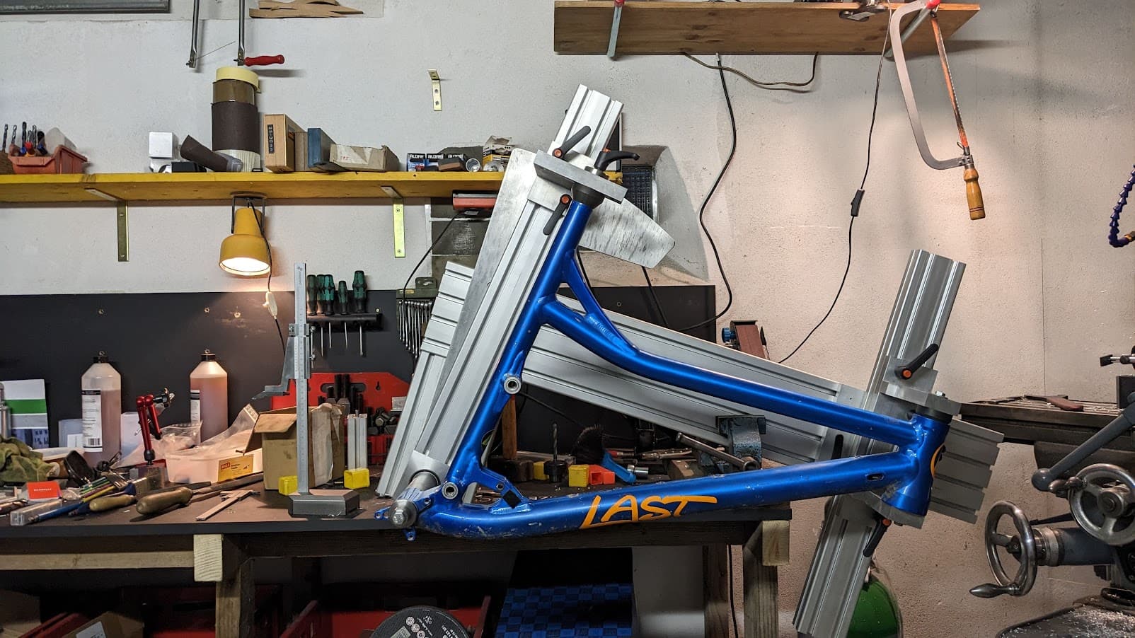
Daniel, can we talk about the different approaches to holding the bottom bracket shell in the jig? There are different approaches to this that a lot of professional jig manufacturers disagree on. Each has its merits.
There are a lot of great jig designs out there. Alex Meade, Joe at Cobra, Todd Farr, the Benchmark guys, Jeff’s Sputnik jig, Drew ar Engin. Joe Bringheli, even the older and not for sale Anvil, Henry James and Nortac jigs. Even the motorcycle eccentric Chop Source jig. If I left anybody out, sorry. This is just off the top of my head.
The two primary approaches seems to be…
I think the reason why there are these two divergent approaches to holding the BB shell in the jig is because of so many different and competing all BB standards. Daniel, is there a method for holding the BB shell that you are leaning to? Any other opinions?
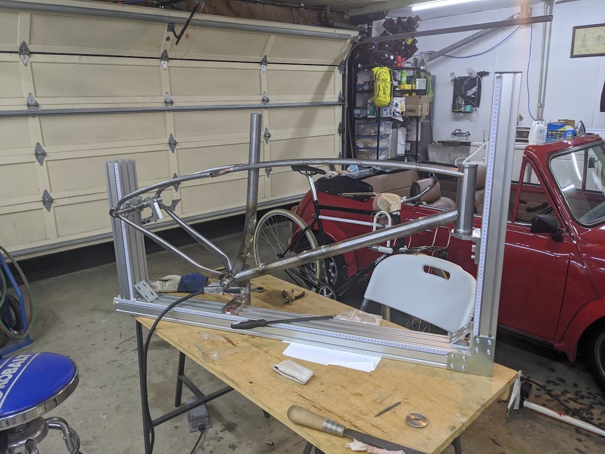
I can officially confirm now, she’s a tank. Could barely lift 'er up onto the table to take the pictures… And that’s only the front end of the whole thing ![]()
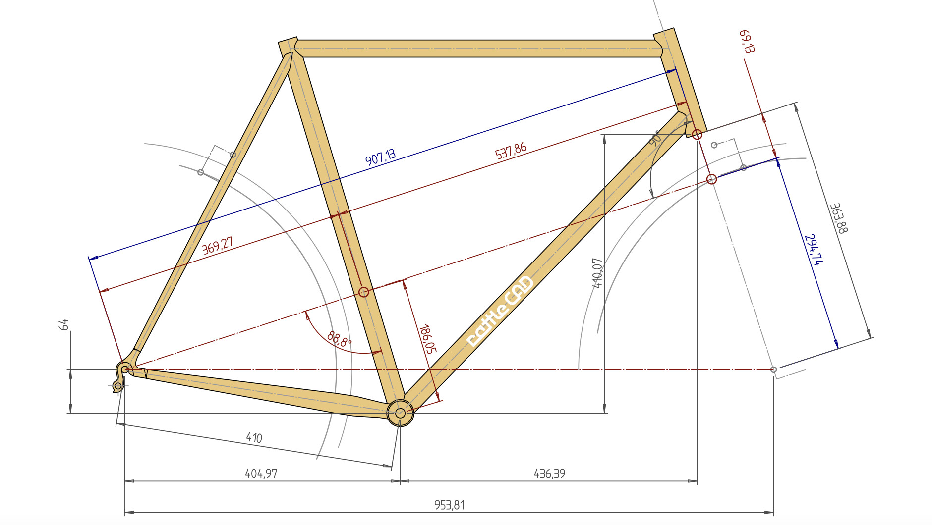
This is a great thread with a lot of good input. I’m currently working on a design remarkably similar to Nick’s using an 8020 style extrusion in a “beam” type jig. One of the comments I see about these jigs is they are difficult to setup. I’ve been working with RattleCAD (somewhat buggy for sure but cheaper than bike CAD) and it generates a drawing providing dimensions referenced off the head tube angle to the rear dropouts that seems like it would make setting up this type of jig very easy. Bottom bracket is fixed height wise, set the distance between it and the headtube as well as the height offset and then do the same for the rear dropouts.
Here s a screen shot showing the dimensions, not sure if this is possible in bike CAD but it seems like it would be easy to add this info.
Late to the thread but I’m solidly team Beam Jig. Made mine around 2017 without any custom machining. Maybe I can make a thread about it later.
But to stay on topic, These jigs are just as easy to set up as an anvil with just a little math and your standard geometry numbers. I use a CAD workflow, but created a spreadsheet calculator for a friend who hopped on for a frame.
Do tell more, looks like a nice solution as well as that frame!
Wow, is that fixture picture generated by a spreadsheet? How did you do that?
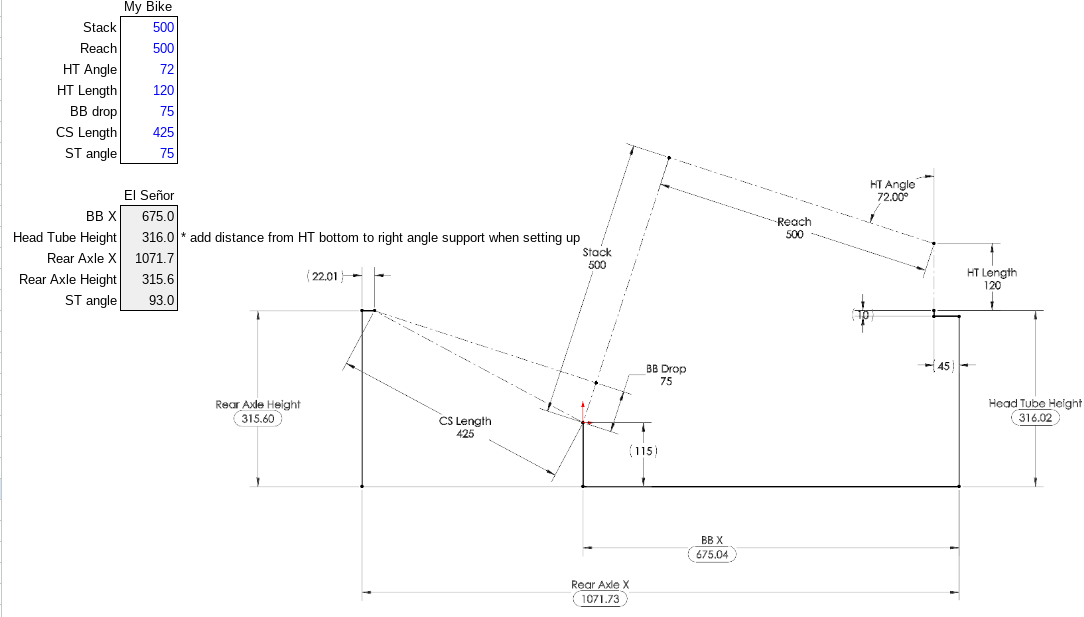
I’m sure it’s possible to plot the jig live in excel, but I think I’d rather spend my time building and riding. The picture is just a screenshot from CAD to identify the driving/driven dimensions.
I’m not sure if this helps anyone else, but here’s the math to save some time if you have a jig like mine. You’ll need to sub your own specific fixed offsets. If there’s enough of us, maybe we can get it in BikeCAD!
| Jig | ||
|---|---|---|
| BB X | 675.0 | (COS(RADIANS(HTA))*Stack) + (SIN(RADIANS(HTA))*B3) + 45 |
| Head Tube Height | 316.0 | 115 + (SIN(RADIANS(HTA))*Stack) - (COS(RADIANS(HTA))*Reach) + -HTL |
| Rear Axle X | 1071.7 | BBX-(cos(RADIANS(HTA))BBdrop)+ SIN(RADIANS(HTA))(SQRT(CSL^2 -BBdrop^2))+22.0142 |
| Rear Axle Height | 315.6 | 115 + SIN(RADIANS(HTA))BBdrop+ COS(RADIANS(HTA))(SQRT(CSL^2 -BBdrop^2)) |
| ST Jig angle | 93.0 | 90-HTA+STA |
Hey @Daniel_Y ! I’ve been following this thread and just returned from @Schonstudio class I’m planning out my fixture to build some more frames. I’ve found this thread super useful but also complicated as it has gone over so many different designs as well as different budget options of both material and fabrication processes.
I am looking for some clarification and direction with a few of the options I’ve seen here. I am most interested in your mock up fixture that uses 3d printed standoffs, cones, etc. but worried about the 3d printed components holding up to tacking. If they can withstand simple tacking I would love to try this design. Furthermore, in this design your “too short” standoffs are pretty similar to the 8020 gusset/brackets, is there a reason to avoid using these brackets besides too short of a standoff for welding?
The bent sheet metal standoffs also seem like a great cost-effective way to get started from what I can tell: your listed cost is $80 for the set rather than the $164 for the slotted aluminum risers. Still both of these would require either cones/pucks 3d printed, from chopsource: $140, ideas2cycle: 140euro, or from Paragon.
With all of these different designs laid out here I didn’t find exact CAD layouts to your designs, I might have missed the post but if you would be willing to share any CAD plans for the sliding plates, cones, etc. or recommendations at this point in the project that would be great! Also did you ever settle on a M5 vs M6 bolt?
Thanks!
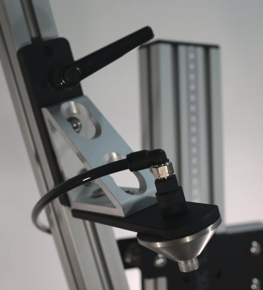
The Benchmark fixture uses the same brackets. They add some flat plate to the horizontal side to extend the cones, and on the vertical side to house the slider handle.
Said it before and will say it again, this is the best design for a budget-friendly jig.
For the cones:
Congrats on finishing Schon Studio’s class! Sorry for not keeping this thread up to date, I have had so many projects running in parallel, and other builders have stepped up by sharing their own designs.
To answer a few questions:
I need to call Send Cut Send to ask about their bending tolerances. I think there is a simpler version of the fixture that uses simple right-angle bent risers.
Let me to a bit of thinking and research on this topic again, and try to update this thread in the next week!
If you design your pieces with slots and tabs you can move away from the bending (and whatever tolerances they have there if that is problematic)
i have designed angle brackets via flat pieces that hold together via slots and tabs and a bolt. It’s more complex but price-wise was similar to cut+bend and much more precise.
That must’ve taken a long time working through the trigonometry to arrive at the jig settings! Thanks for posting the formulas. Are sure sure the formulas are accurate though?
It seems that the formula to calculate setting the Jig ST angle might be wrong. Or maybe I am overlooking something. The example frame you have seems to suggest that BB drop is a variable in setting the seat tube angle for this jig, but why? It doesn’t seem like BB drop should be in the equation to set the Jig ST angle. I would think that the formula for calculating the Jig ST angle would be equal to 90 + difference between the ST angle and HT angle… or stated like this…
ST Jig angle = 90 + (STA - HTA)
ah! you got me, I was converting it to human readable from cell references and had a typo. Edited above. Thanks for checking
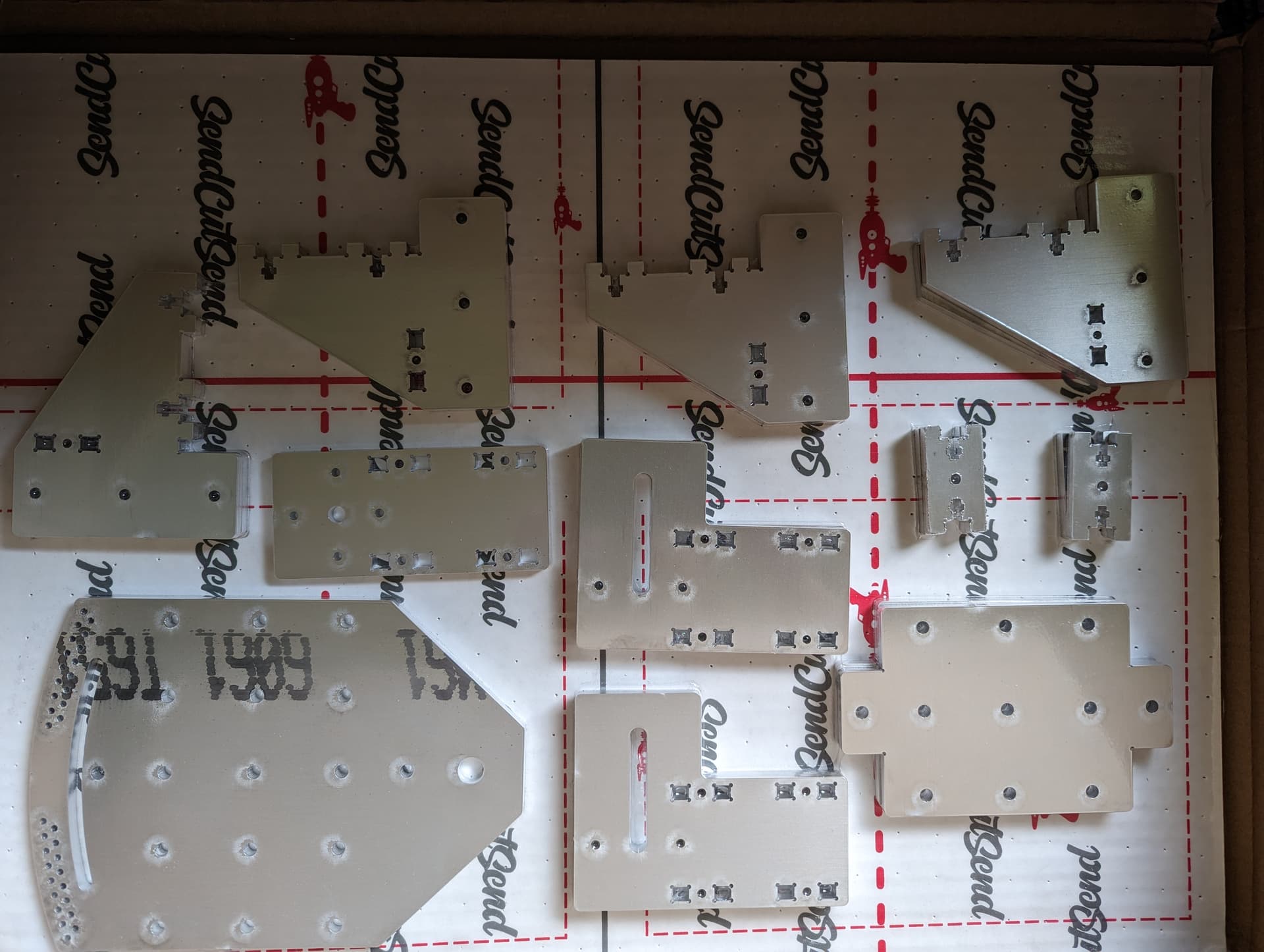
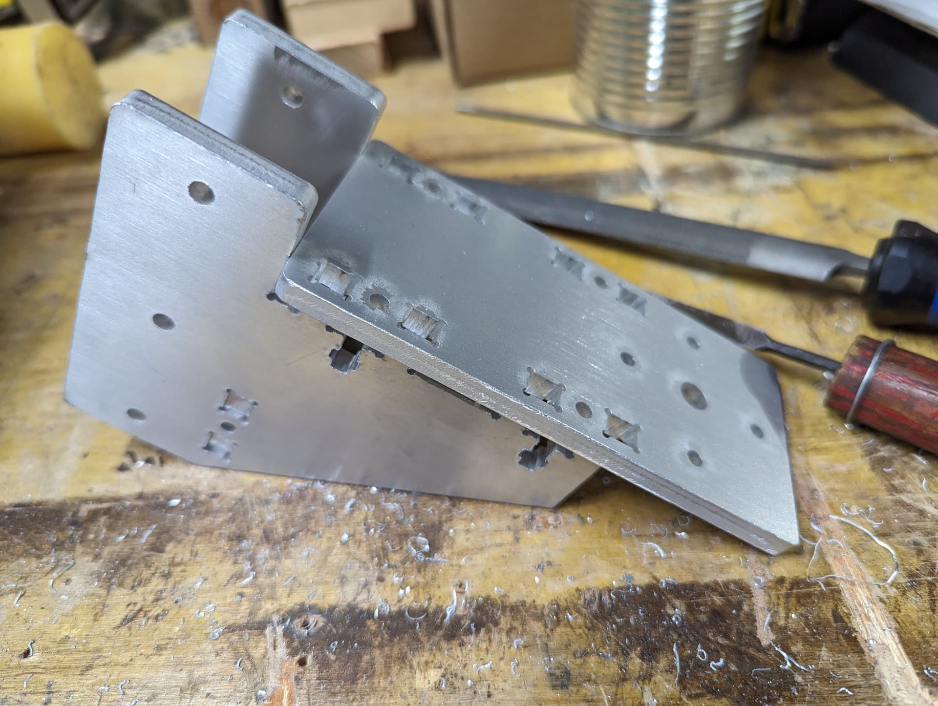
I have jumped in the deep end and got the laser cut parts for @Daniel_Y’s last iteration of the OS Bike Frame Jig. I started cleaning up the parts yesterday and hope to have the jig together by sometime in June.
The pettis joint seems to work just fine, once the fit is dialed in. I haven’t got the M4 bolts and nuts yet to clamp it tight, but test fits show a square alignment between the plates.
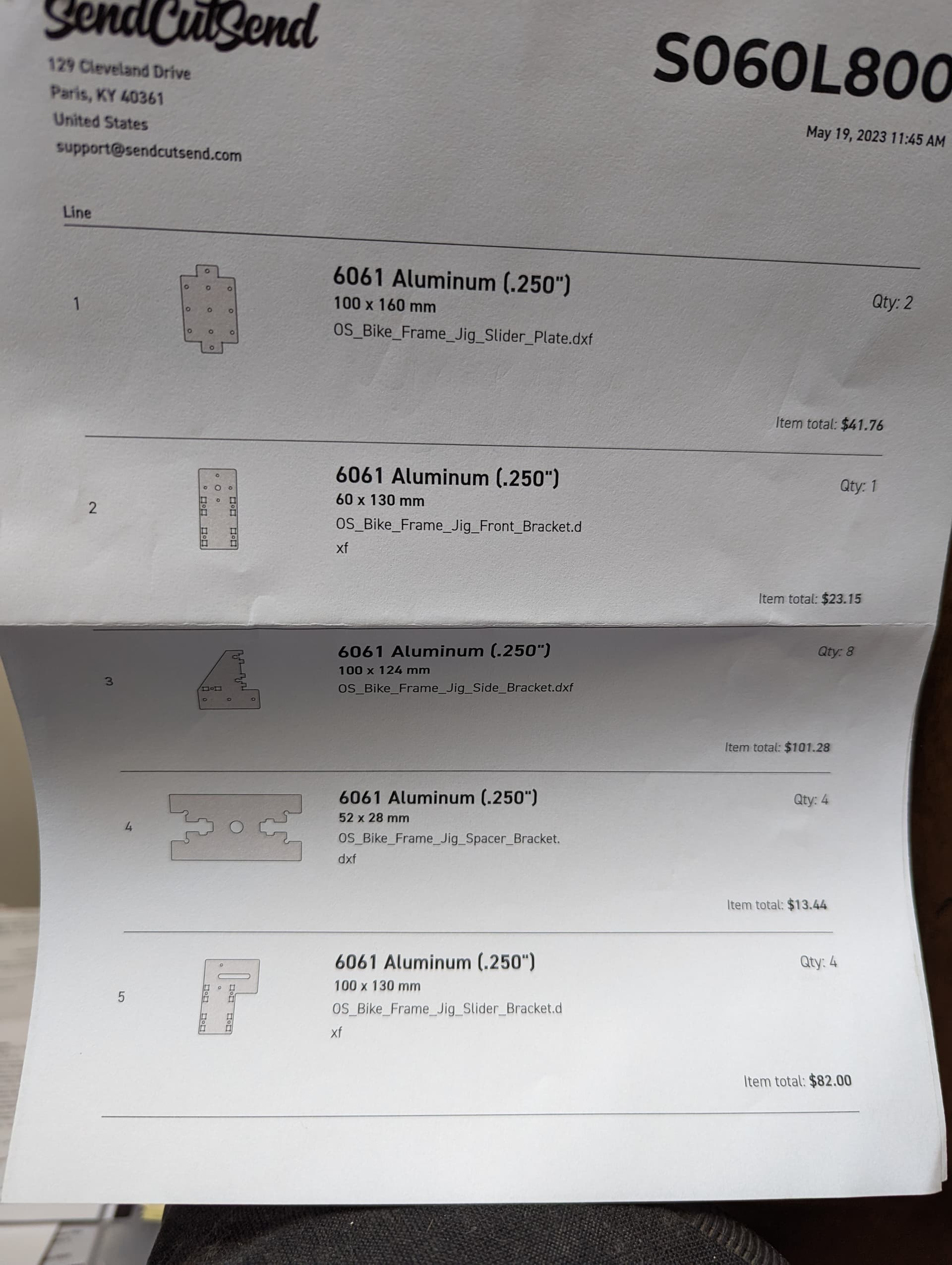
The cost came out to $355 USD with tax, and happily SendCutSend has an office just south of me in Kentucky so I had next day shipping. Woo. This covers all of the plates needed for the 8020, but not the bent plate that Daniel designed to hold the dummy axle. I am still looking at that and need to talk to them about tolerances for bending.
I am deviating from Daniel’s design with a longer main rail of 8020 because my goal is to build longtail cargo bikes. I also got Joe Roggenbuck’s frame stand kit to get the jig off of the table.
More to come soon, hopefully.
Very nice! Thanks for piloting the design. I hope it works out! Looking good so far
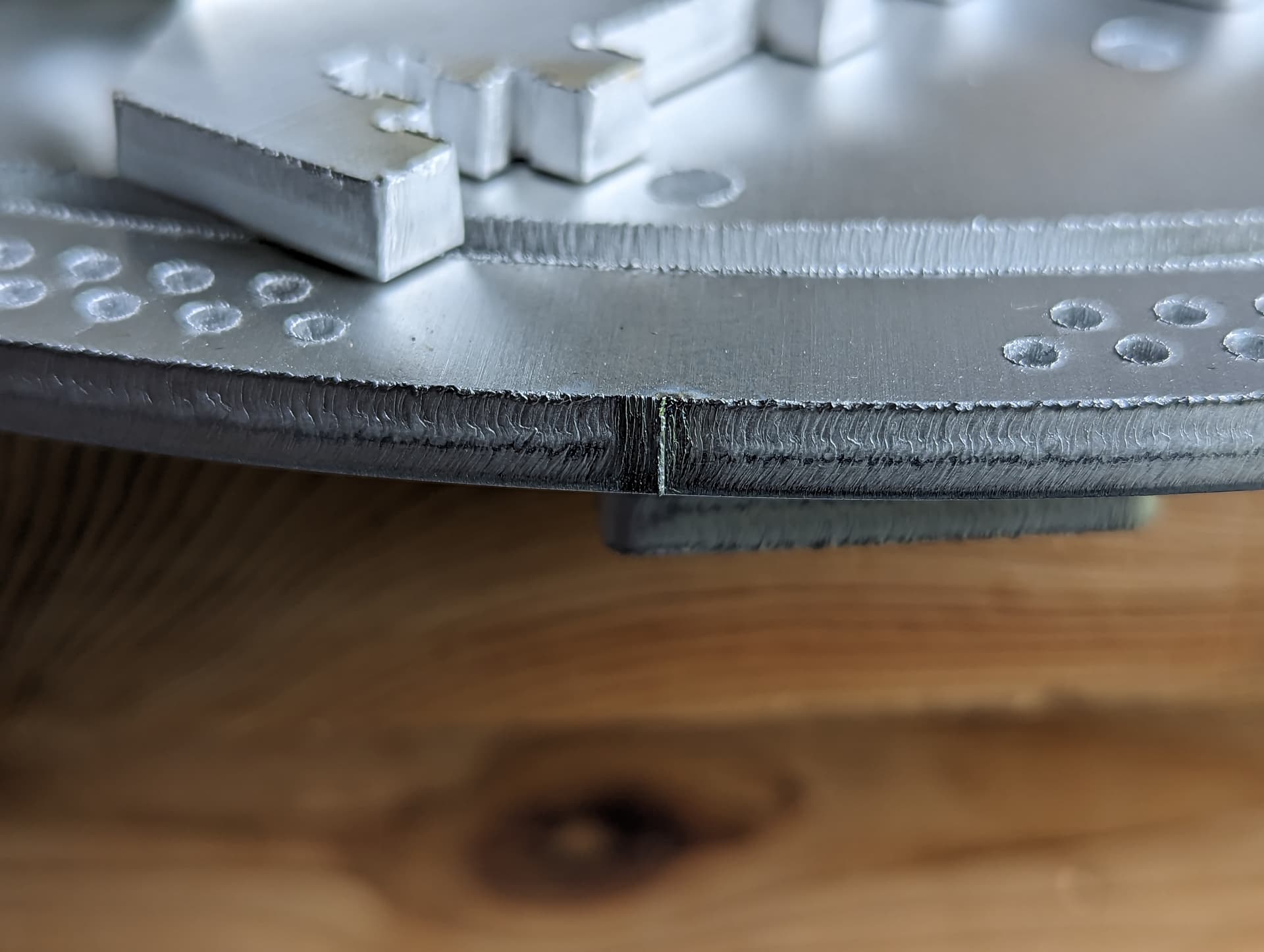
I just checked SendCutSend’s website, they seem to also offer waterjetting. Especially in aluminium, this would result in a better edge finish and no (or next to no) taper.
Aluminium is not easy to laser cut, since it is more reflective than steel and conducts heat much more, so you need way higher power settings on the laser which in turn leads to this frayed edge.
That’s good to know, thanks!