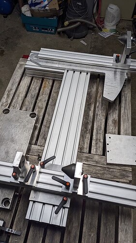
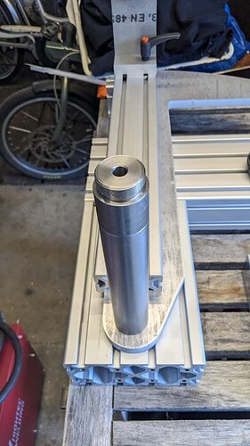
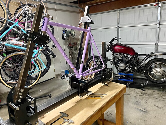
Getting there slowly, a few bits still missing…
But I might actually be able to make the <1000US$ target. If you buy the non-branded profiles it should be fairly easy
Setup time with the Anvil jigs is, at most, 30 seconds, from numbers out of BikeCAD.
So it might as well set itself up in terms of time invested.
-Walt
the fixture I’m building is kind of a cobra-style jig at least in terms of how the setup works. The numbers can be exported from BikeCad or also easily integrated into a technical drawing from Fusion or SolidWorks or whatever CAD you’re using.
I chose this style of jig because it is also quite easy to manufacture, because it only has one pivotal part (the ST mast) which is not a slider, and two sliding bits which do not need to rotate (the HT and rear axle). Less moving parts → less slop, easier to package and manufacture and also cheaper
Hello all,
Long time listener, first time caller.
Lots of great ideas and feedback here, so I thought that I would throw my 2 cents in.
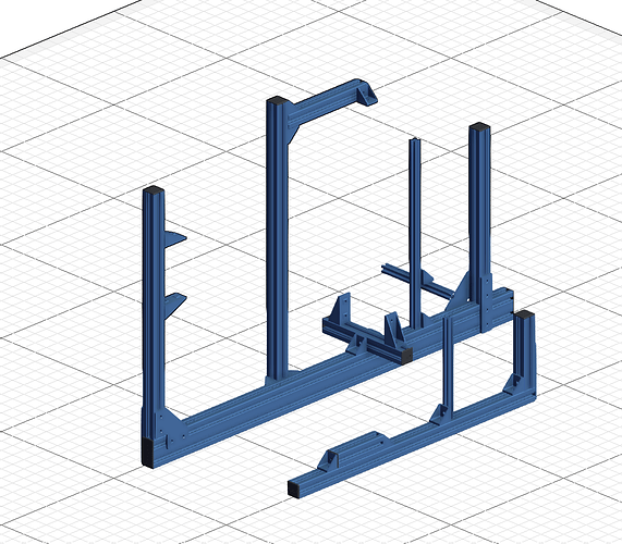
Here is a design that I have been thinking about on and off for a year or so:
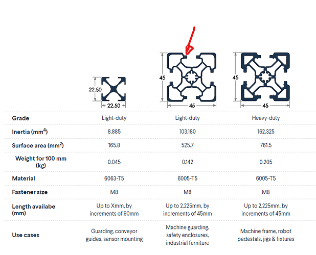
The parts shown here are all designed using the Vention brand of extrusions. Their sales pitch is that the have “high precision” locators that interface with extrusions for greater accuracy.
As a long time BikeCAD user, the built in Cobra outputs for X,Y co-ordinates will be used for jig set up.
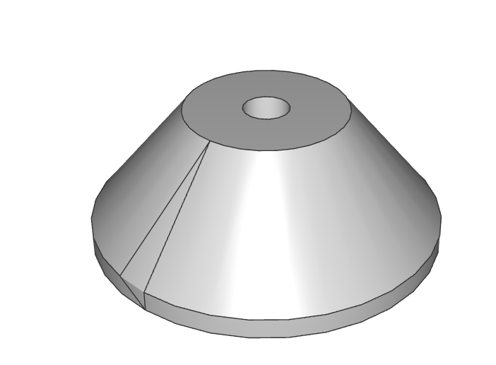
The idea would be to buy this set up from Vention, then complete it with head tube cones, BB cones, seat tube cone, and a rear axle holder.
I recently designed the cones to be universal to cut costs (5x of the same part)
I came up with something similar to what is posted above, but the discussion here has me second guessing myself. I do agree with an M8 bolt though.
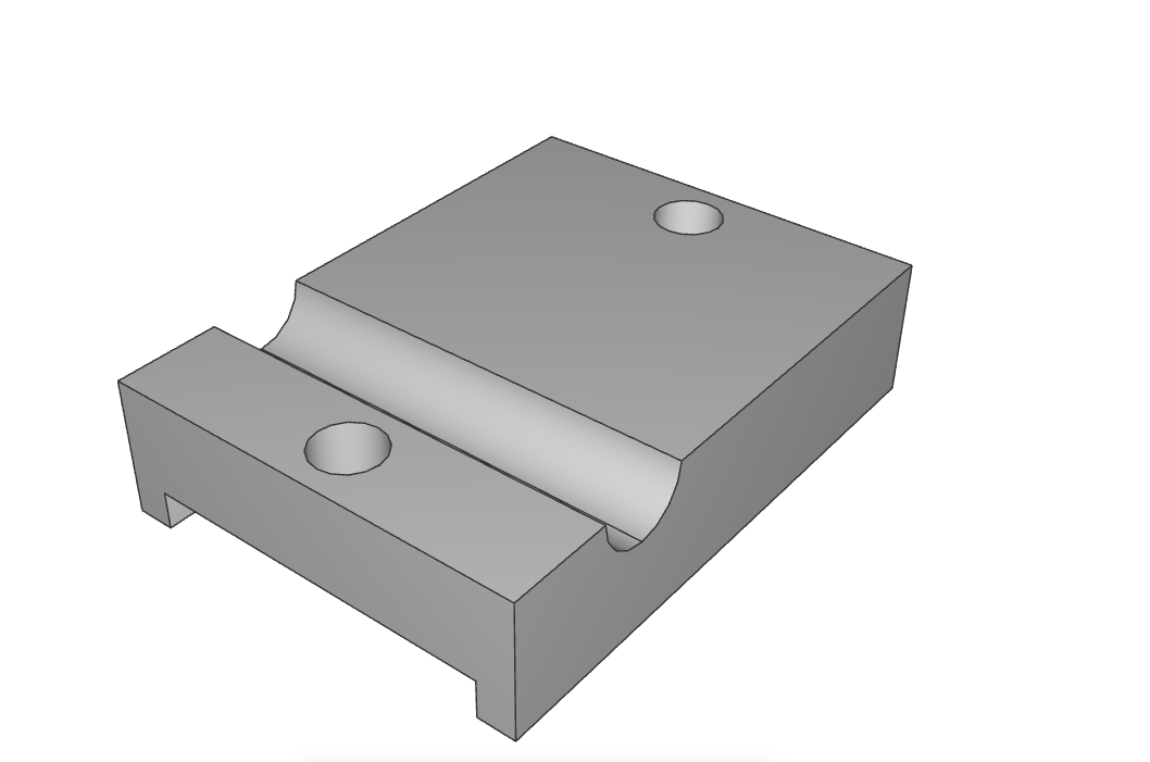
From some recent forum lurking, I have learned that a V section is prefered to the round slot, so I will re-design that soon.
This design requires “locators” from which to measure the X,Y co-ordinates to (a point in space that is the same height at the center of the BB and is directly below the center of the axle. Same for the headtube). I have 3D print designs for this problem.
In the first picture, there is also a fork fixture. I am not planning on doing forks any time soon, but I may just order the extrusions to save on shipping later.
It needs a V-block for the steer tube, and an axle holder similar to above but spaced for front axles
Right now, with some of the quotes that I have, I am looking at about $1650 Canadian (so $1225USD) for everything (frame and fork) shipped to my door. That includes the cones and axle holders made from SS.
I would still need some dummy axles. Current plan is to stick with the PMW standard.
I have more pictures to post but as a new user, I am limited to 1
Ah interesting, I have never heard of this brand before.
Their profile has a slight divot, which could work great with the adjustable sliders we use. Let us know how it comes out!
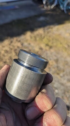
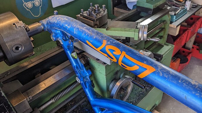
Built this thing today: My design uses a BB Post that needs adapters to hold different BB widths (I’m not a fan of the anvil adjustable BB post thing…). Did some thinking about these adaptors and thought it might be useful to have a NDS BSA thread (if the fixture is used driveside out) on the adaptor to prevent the user (le stupid me…) from accidentally inserting the BB the wrong way around. Smart or overkill, what do you think?
(didn’t have a BB shell kicking around so used an old frame to check fitment…)
Nice idea! I am guessing this is a “BB puck” so it stays with the frame when you remove it from the jig? Otherwise, I am imagining spinning the entire frame to get it off the fixture ![]()
That could be a good idea for professional jigs too. might act as a heatsink too? The chance of a flipped BB is terrifying. There is no engineered safety system in place, so its always down to visual confirmation.
I like the idea! I’d just be sure to remove that before welding it out. Unthreading that puck, dry no less, out of a slightly warped BB shell would be a nightmare. Don’t ask me how I know ![]()
I think anything 8020 based for the most part will be versatile enough, and my seat of the pants feeling is that beam style would lend itself most nicely towards the ability to fixture subassemblies and pivot locations. I can’t think of any provisions within this project, but it’s an interesting question. Maybe some basic strategy or documentation on how to fixture custom pivots/ locations/ seat tube locations?
Yup, this is only suitable for tacking, nothing more serious… Which prevents it from acting as a heatsink unfortunately. But I guess it would not be a good idea anyway to only extract the heat from one side of the BB shell, might result in asymetric warpage. But I’m getting way ahead of myself here ![]()
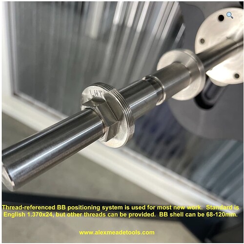
Alex Meade uses threaded BB fittings for his jig: https://alexmeadetools.com/product/freestanding-frame-fixture/
Interestingly the BB floats horizontally on the shaft. His theory (based on a lifetime of engineering) is that the frame is over-constrained if the BB is fixed on the shaft horizontally.
Well, he’s constraining the seat tube instead… but there must be some kind of reference to put the seat tube on the centerline of the BB shell, or the BB shell centerline coincident with the frame centerline.
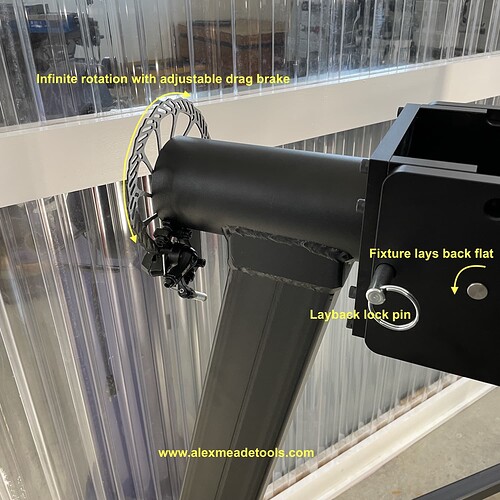
Anyway, by far the coolest feature on his jig is this:
Haha, awesome. I was just about to build the same style of stand using disc brakes in the same way.
What would be the Paul’s Klamper upgrade?
I still think that the TBA design is the best/cheapest to manufacture for a jig. It’s far from perfect, there are areas that could be improved and it’s not ideal for a fast paced environment
Ultimately I believe one could use the same technique that is used to build flat tables to replace some of the parts in the LCFF design and save on space/weight but you will need a tig or mig welder.
@nickhiti1 the more I look at it and the more I think you are onto something with your design.
@Daniel_Y I am getting closer!!
Looks like I’m a bit late to the party on this one ![]() For what little it’s worth …
For what little it’s worth …
If @Daniel_Y’s frame jig had been available when I started, I would have built it without question. The (really) cheap starter jig world was a mess. When starting, I’d read that a jig wasn’t required. Neither was a mitre cutting tool, etc. But I wasn’t interested in hand filing mitres and I wanted a proper jig - I just didn’t want to pay for it! So I bought some 120x40, 40x40 and 16x40 extrusions, fired-up the 3D printer, and made my own. It sucked … a lot!
For my current build (technically my 3rd, although I aborted my 2nd after I screwed up the front triangle), I’ve made PVD’s Skynet jig. Cut a few corners during manufacture, and I mounted it to a wooden board, to save money. I reckon it came in around 500-600GBP for materials and a few months to make as my first machining project on my Chinese mini mill and lathe. Trial by fire, but it turned out well enough.
Things I like about it so far:
- Free plans, very well documented
- Easy to source materials
- Fairly straightforward to make the parts, and they seem to be very accurate
- Rigid
- Easy to add/remove tubes once you’ve done the initial setup, and should be really easy to remove the tacked frame too
- Easy to put supports anywhere (tube holding, suspension pivots, whatever you need) on the backboard
Things I don’t like about it so far:
- Designs are US-centric so I needed to do some work to convert it all to metric
- Time-consuming to make and one or two of the parts pushed the limits of my tools
- It’s getting crowded around the chainstays (partly due to my backboard being a little too small)
- Tweaking ST position to allow for missing your mitres is less trivial than I’d like because the ST angle is separate from its X-axis position
- Doing all the maths for setup, and double-checking fixture positions before you commit to cutting tubes, is a real ball-ache. I appreciate trig is useful for frame builders but the abstraction from basic frame geometry makes it less approachable for the novice
- I’m not sure how easy it’s going to be to access the back-side of the tubes for tacking. My offset is 160mm and I note that PVD’s raised it (again) to 180mm in a recent blog post
I decided not to go with the WOPR jig in spite of it being a lot cheaper and quicker to build as it just adds more maths into the setup. There’s a kernel of a great starter jig in that design but it’s far enough off the mark that I wouldn’t recommend it at this time. But I wonder if there’s things to be learned from his designs. It might also be really nice to incorporate a standard way of attaching those 50mm/2in matrix welding fixtures to your jig as an option, to allow for placement of things like extra tube support or pivot points without needing to have extra beams hanging off your main supports at all angles.
Anyway, great work - I’m looking forward to seeing where this all ends up and may consider building one in future if the Skynet thing doesn’t work out for me.
Addendum: if you’re going to rely on BikeCAD to provide complex jig setup calculations, make sure they’re available in the free version. I’d imagine the number of people who want to spend as much on software for their first build as they do on their frame jig is quite small.
Thanks for the detailed writeup of your experience.
This is a good point. I have been trying to understand the availability of stuff in eurpoe, asia, south America, etc… to create more universal designs
Also another great point. For my fixture design my progress has stalled a bit because I am researching some of the new low volume and rapid prototyping services available like PCB Way. There might be a lowcost fixture solution that leverages designs for those services.
Another great call-out that I have not considered. I think there might be two solutions here:
- an google spreadsheet that converts the BikeCAD dimensions to a custom fixture coordinate system
- Ask BikeCAD to add the beginner fixture to the free version.
I would imagine an introductory fixture would be a gateway to frame building and BikeCAD pro purchase, so it’s a win win for everyone.
If I recall correctly, one of the innovations of the LCFF is the ability to align it with a laser. Allegedly, that is what enables them to use non-precision beams. I am curious about what your thoughts are about the laser alignment. Does it really do its job?
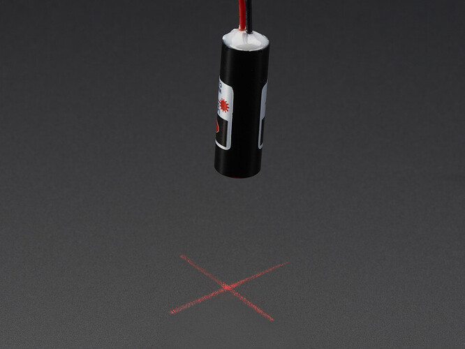
Laser line didoes are really cheap, they can be an easy addition to any fixture. You could even make a headtube dummy that accepts this diode to align any fixture:
I think it does, It’s incredible how NOT STRAIGHT some of the tubing are, I would have never imagined that 5ft of 5x4 steel tubing could be THAT crooked, the laser alignment is definitely needed, once you align it, it’s set for good, you should check it every time you are about to put a frame up but I would be surprised if there are major adjustments to be done every time. It’s a valid solution.
Small adjustments are a little tricky as everything is heavy, would be neat to have some trapezoidal threaded rod to move each part, that would make it easier to setup precisely but then price goes up.
I am actually playing with some new ideas, we’ll share soon.
On a different note, I am realizing that a fixture/jig is the #1 obstacle for us hobbyst, you can get an AC/DC Tig welder with pulse for less than $700 nowadays (even less than $250 if you don’t care about AC), you can get tubing+welder for less than the cost of a (good) new frame, the real issue is the fixture!!
