I am working toward making a frame. I’ve made lots of individual components over time, but never a frame. I work in the 3D Printing (AM) world, specifically with Laser Powder Bed Fusion, so my projects tend to feature it.
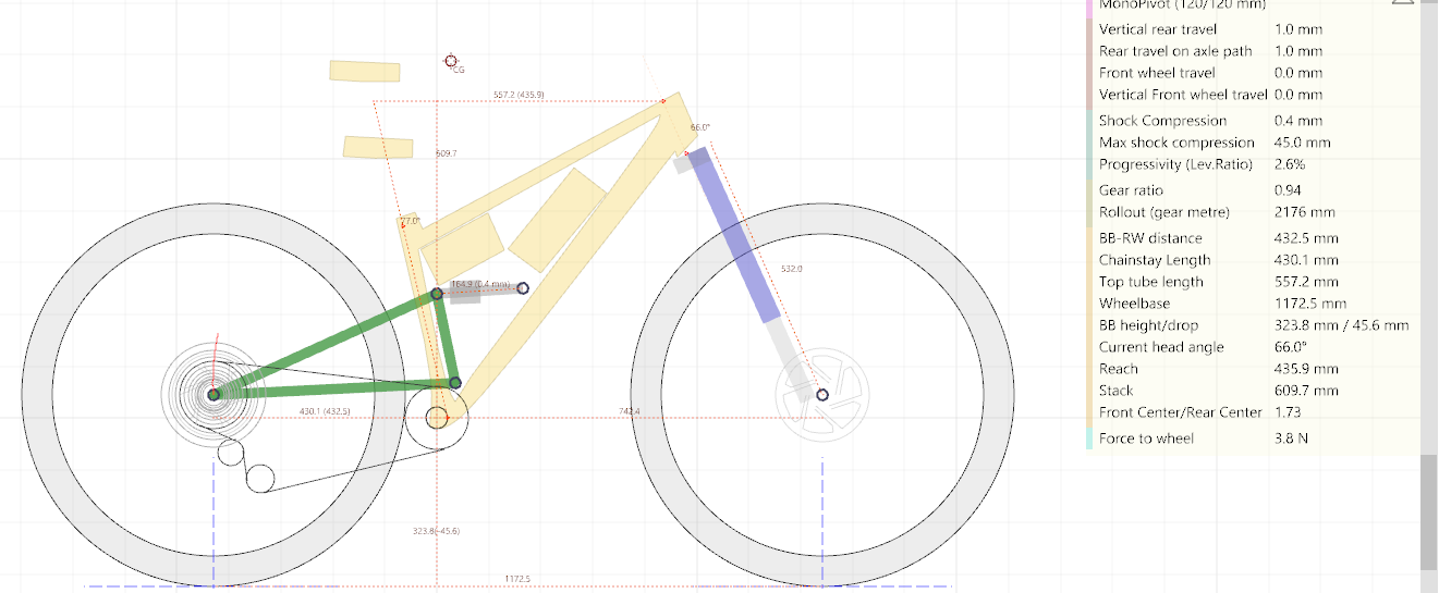
I’m planning for this first frame to be aluminum lugs, bonded to carbon and titanium tubing, but the concept is still in flux. I’m thinking of doing a nice simple single pivot, with around 120mm travel and ‘modern XC’ geo. It can be fairly ‘light duty’ as I am small and only 125lbs.
I am currently planning to use a carbon down tube that is 1.875" OD with 0.0625" walls. I am nervous that the single pivot into the downtube could buckle it… To combat this I was planning to:
Make a large spreader plate at the front shock mount, to reduce the point load
bond polymer plugs into the inside of the downtube, around where the shock mount will be bonded, to help prevent the tube from collapsing.
Does this carbon downtube seem risky? Would it be smart to spend alot more $ to get a ~0.090" thickness tube?
But the biggest question will be how to crunch those numbers for your carbon tubes and how that will interact with the bonded lugs. Short answer is I don’t know because while carbon is very strong, it is less uniform than 4130 for example. I know a lot of carbon seat and chain stays are 1-1.3 mm thick so it sounds like you might be on the right track for a light duty XC bike but I am not a carbon expert. Hopefully someone more knowledgeable in composites can chime in but that’s where I’d start.
I am small and light (I weigh 125lbs/57kg), and not hucking big features. Light duty a good description for me.
For the specific tubing- I am looking at roll wrapped stuff, since since it has 0 and 90 degree plies that are supposed to be best for bending and crush (as far as CFRP goes…).
When I look at off-the-shelf aluminum and titanium downtubes, they are thinner than the CFRP tube I am considering, so that gives me confidence the CFRP tube will be OK (with a spreader plate), but the directionality and inconsistency of carbon makes me nevous.
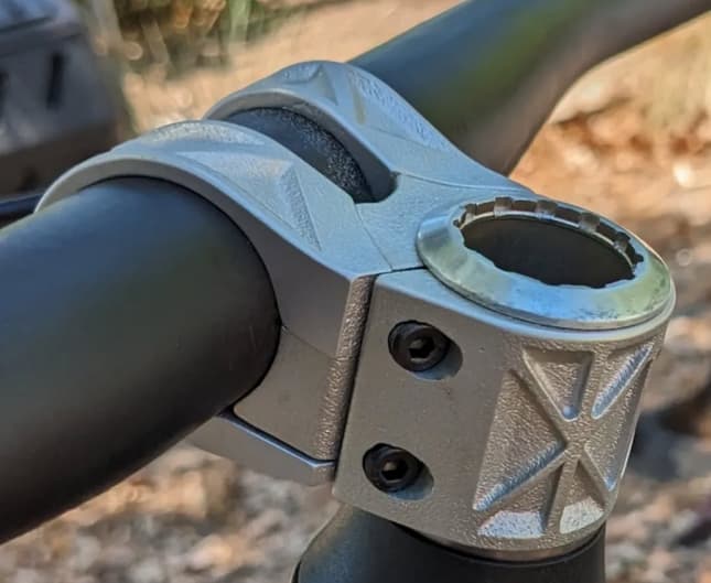
I am honestly less worried about the lugs, than just having the down tube buckle+crush in the middle where the shock is coming at it at nearly 90 degrees! That said… I have been running some printed parts without issue for quite awhile that look a bit risky to some eyes. The best example of this is probably my stem. This is printed in Scalmalloy. I am a specialist in 3D printing, but a novice in CFRP.
Good question- I’d love to use brazed lugs, and I delayed this project YEARS to do it that way! I simply don’t have the skill or the space to braze/weld and I want to try and do this all myself. I decided I was sick of waiting and am doing this with bonded joints on aluminum lugs. On the printing side, I also strongly prefer to run aluminum (AlSi10Mg in this case), and have much more frequent opportunity to run personal parts in it compared to any other alloy.
Give me a couple of years and I likely WILL do another frame brazed or welded as well.
If anyone has thoughts on my planned downtube… I’d love to have them. I have found a source to get 0.090" wall tubing of the same ID that I may switch to. It adds a bit of cost and weight, but may reduce my risk of bending/crush failure.
I’d also love to hear people’s thoughts on the effectiveness of a spreader plate( at shock mount), and bonded plugs (inside tube around shock mount) to reduce this risk.
realistically without knowing the exact layup there is only so much you can tell, and even then there might be substantial differences between manufacturers depending on process and materials used.
The downtube typically also contributes substantially for the torsional stiffness, and typically you’d find a layup using unidirectional fibres along the tube to give the overall strength, as well as fibres diagonally to take the torsional load and are responsible for the hoop strength (not ideal fiber orientation, but good enough with how much biax is typically in there). In my DT I usually some extra reinforcement for rock strikes and the like.
Personally I’d definetly go with the heavier tubing. The weight penalty is not big, but you’ll get the stiffness advantage in the front triangle and some peace of mind for the last tube you want failing.
Introducing the load with a nicely designed shock mount should be fine, but again - without layup hard to tell.
Hi Lester, This is excellent feedback. The full layup info is not provided by the 2 venders I am looking at, but they both say ‘mostly’ 0 degree, and ‘some’ 90 degree.So its all 0 and 90 roll wrap.
I think I’ll source the thicker ~0.090 and sleep better. Should I bother with my idea of bonding in a a plug of material on the ID of the tube, under the shock mount? I was planning on using printed carbon fiber+nylon which bonds well and has high stiffness. It also has the added benefit of giving me in-tube guides for internal cable routing…
The thicker tube I am looking at has a couple of 45 degree plies. As you said above that would help with torsion, maybe another reason to get the thicker tube.
A note on my design- my downtube will be only ~600mm long (~24") and have long lap joints on both ends. So the unbonded length of tube will be something like 20" (500mm). As I said- I am not a big person (5’5" 125lbs)! I am hoping the small overall size also helps me with this point load bending failure I am worried about.
Fair, I’m still learning and gathering supplies to get started on my first silver brazed lugged frame and I started seriously looking into it over a year ago.
The spreader plate idea sounds pretty decent actually, with carbon it’s not too difficult to get ahold of some carbon cloth and epoxy and locally reinforce the tube. Just gotta make sure you use plenty of resin and get good compression on the fibers to squeeze out the excess along with any air.
Take my advice with a pinch of salt though, I don’t have any experience with carbon in bike frames, I only worked with carbon at a rowboat company.
Sounds like a super fun project. Frame-wise, aside from the feedback that has already been offered, I have nothing to add.
However, your stem caught my eye.
I’d highly recommend that you inspect the bolts and the mating thread in the stem.
This design puts a high shear load on the bolts from wrenching on the bars. Much more so than when the bolts are at the back of the stem.
I had a BMX stem back in the day that had a very similar design, and I remember that the bolts kept bending and the thread in the alloy body got pretty chewed up. Especially at the thread entry.
I personally love the idea of eliminating the bolts at the back, and I’ve designed more than one stem with that in mind, but from experience, it has its drawbacks.
@Hananas Raleigh made some bikes BITD that were steel or titanium tubes bonded into aluminum lugs. They were called technium. There were some problems with debonding at the bottom bracket, but I think that’s a production issue not the materials.
Once you increase the wall thickness and start inserting plugs I don’t think you get anything from using carbon except it looking fancy.
I would be tempted to print the bottom bracket and down tube lug you are planning to use, bond them to a metal tube and then load it like the shock is going to and see what bends/breaks.
Hahn Rossman
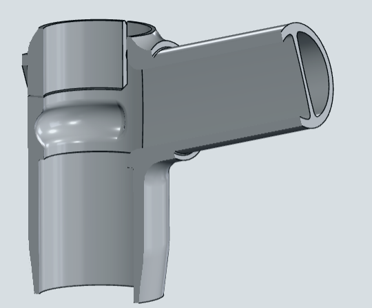
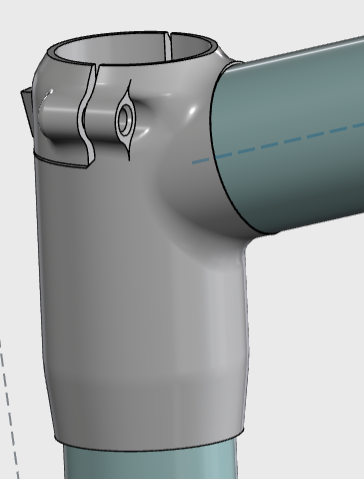
@Constellation - oh I’m all over the fillets. Wall thickness will vary through each lug and fillets and stiffening walls added where I think it needs a bit more safety. Here’s a cutaway of the seat tube lug in current draft.
I am planning to use adjustable dropouts from Esker Cycles. They seem like a good option to easily incorporate into printed lugs without needing precision machining. They also give adjustable chain stay length. Does anyone happen to have CAD of these things? I’ll be reverse engineering them if not. Parts arrive today!
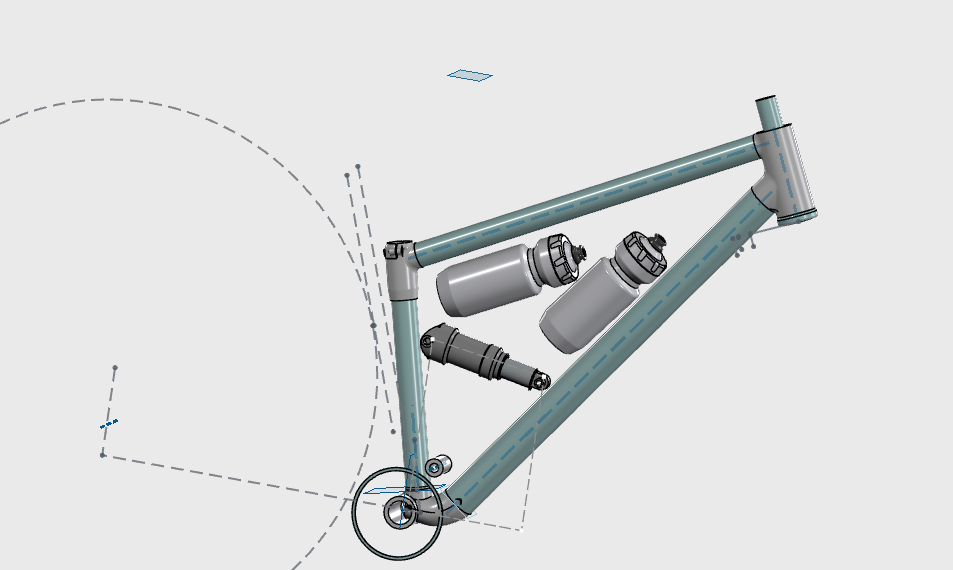
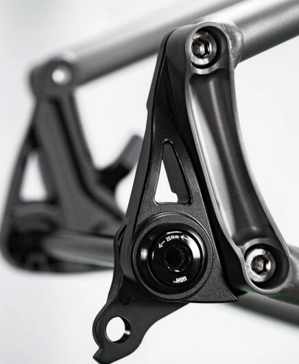
For the main pivot I am planning to use parts for a Santa Cruz Heckler 5. This gives me the pivot axel, hardware, bearings, and most importantly- bearing caps. By using those I can reduce the precision I need to maintain on my printed parts around the pivot. Check it out:
Other random details I figure’d I’d share:
Shock- 165x45 trunnion mount - this gives me shorted possible length of shock, I also like the bearing mounts of trunnion style shocks. I AM likely going to use a float DPS or float SL, because they seem to give the tightest clearance on the trunnion side, and let me tuck the shock lower and help with water bottle clearance… but I am tempted to compromise and allow space for larger shocks… tbd.
headtube- 44mm ID for EC44/ZS44 - this will give me the best shot of finding someone to help me ream it to size! I honestly picked this standard for this reason alone. At some point I’ll be begging for help with head tube reaming and bottom bracket threading…
tube-in-tube internal routing - I am planning to design in some tube guides to the lugs, and then use PVC or silicon tubing to guide the cables and prevent rattle. Anyone else doing that? If so, do you have a preferred tubing you can point me to?
Approximate tubing sizes selected so far are as follows. Being honest alot of them were selected just because that is what I can find!
downtube: CFRP roll wrap, 49.2 OD, 2.4mm thick
top and seat tubes: CFRP wroll wrap 34.9 OD, 1.6mm thick
Couple thoughts,
Even though you’re on the light side I would go up to 19mm for at least the chainstays, perhaps even 19mm s.s. and 22.2mm c.s.
The downtube at that dimension seems to me like massive overkill and would not ride very well. I’d be thinking around 42-44mm with 1.6-1.8 wall. A lot depends on the layup here.
The Idea of an internal sleave sounds neat though, perhaps a simple 1mm wall carbon tube
@Rhodefab - For the downtube I was originally going with 1.7mm wall DT (roll wrap, 0 and 90 plies), and would prefer it if it isn’t going to buckle and fail. I was worried about loading the load direction from the shock being nearly orthogonal and causing the tube to buckle. Either way- my plan is to print the front shock mount ~100mm long or so, and have it wrap around ~120 degrees of the tube to help spread the load out. This would be bonded to the OUTSIDE of the tube.
Additionally, I was thinking of bonding in 2 or 3 ‘pucks’ in the ID of the tube under the shock mount to help prevent buckling. The ‘pucks’ would be printed in SLS nylon+CF, which has high stiffness.
Have you seen folks use relatively thin (1.7mm) CFRP tubes in this load case without issue?
I want to believe you and go with the thinner/lighter/cheaper tube! What’s your confidence level with this added info?
Side note- I received the Eskar Cycles dropouts today- that are beautiful. Now I have to reverse engineer them so I can design my back end around them. If anyone has the CAD already- I would be eternally grateful if you pointed me to it.
Loading the down tube in the fashion shown is less than optimal, I think the op is aware of this. An internal sleeve rather than three hard points would be the path forward.