@Rhodefab - I appreciate your feedback. I am looking at options for sleeving the inside of the carbon downtube with a bonded in tube reinforcement. The tube I am designing around is 1.75" ID (44.45). It just so happens that rockwest sells a ‘ferrule’ product that is MEANT to be bonded into a 1.75" ID tube (its 1.74 OD). That may just work to toughen up the thinner tube, so I can run the ~1.6mm wall with some confidence. However, I am not sure how to properly bond the ferrule tube in! If I need to insert it all the way down to the middle of the downtube, there’s no way I am getting anywhere close to a fully bonded surface reliably. Presumably I’d glob/spread the adhesive into the downtube (planned DP420) with a brush on the end of a dowel or something, and just make my best attempt at spreading it around, then push the internal sleeve in and hope for the best. Sounds like a mess. Any thoughts on that?
If I can’t make myself confident in the 1.6mm tube on its own, or a method to sleeve the ID, I’ll just go with the thick/heavy/expensive tube.
Just a little progress report- I’ve done lots of CAD work, including a corrupt assembly file necessitating re-doing a ton of work, and discovered a couple of mistakes in both my geometry and CAD that blew everything up. Better to find it now I suppose!
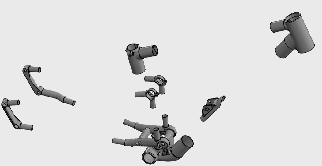
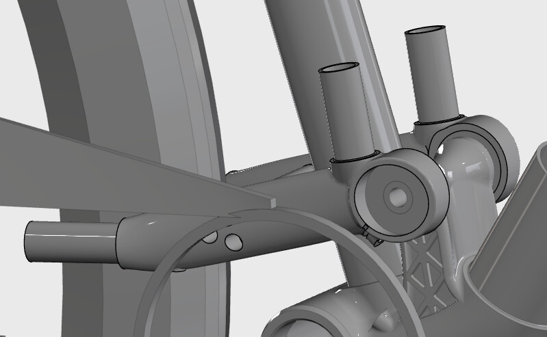
Here’s my current bottom bracket lug. I think its… ugly… but I haven’t figured something better out without adding a ton of mass.
I’ll be working chainstay and seatstay stuff next. That’s certainly the hardest part. To be honest I left that till later so I could get to know this CAD package a bit more before doing the tougher models.
Those are both good suggestions, and concepts I’ve been exploring. I really like the idea @Delvincc has there, and it would give the frame a more conventional appearance, but it adds more bonded joints, which I am trying to avoid.
On the other hand, extending the lug tubes up higher adds mass, and maybe even more importantly adds more ‘visual bulk’ to the BB area, which starts to make the bike looks like an E-bike to me… which I want to avoid like the plague. I am feeling a bit resigned to my oddball looking lug design for now. It’ll end up mostly hidden by the chainring/chainstay/pivot linkage anyhow.
The lower shock mount is mostly loaded in a compressive direction so if you have a curve base plate it would sit super neat bridging the two tubes and almost self locate into position.
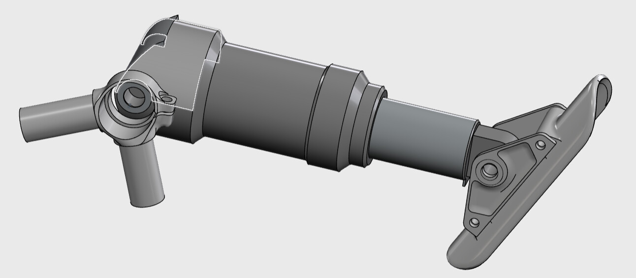
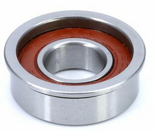
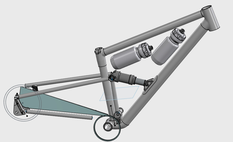
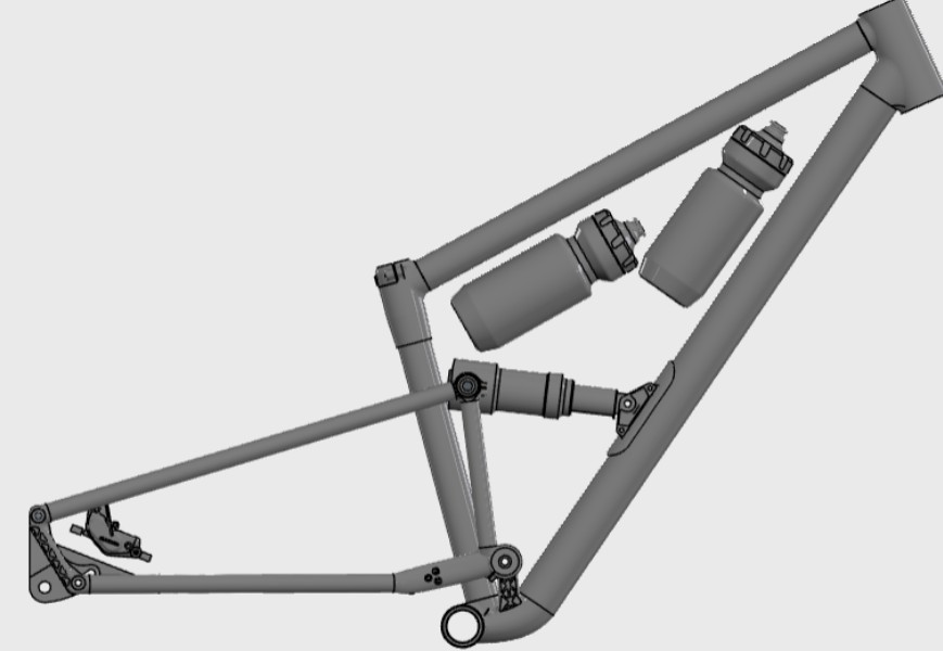
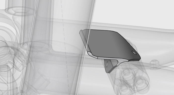
First, I’ve got working drafts of front and rear shock mounts. I plan to print the rear shock ‘lug’ in Ti64, though I’ll settle for 316L if I dont find a good chance to print Ti anytime soon. I opted to make the trunnion bolts install with a pinch bolt to avoid needing to make press-fit tolerances on the bearings. I’m also using flanged bearings to make assembly easier and part precision less important. That is a 165x45 trunnion mount, designed to mimic the clearance of a float DPS or SL.
The front mount ‘plate’ that gets bonded to the downtube will be aluminum (AlSi10Mg), and I plan to make the shock mount plates out of Ti64 or 316L. I kept the plates separate components which are bolted on, so I can swap them out and adjust geo/travel later if the mood strikes me.
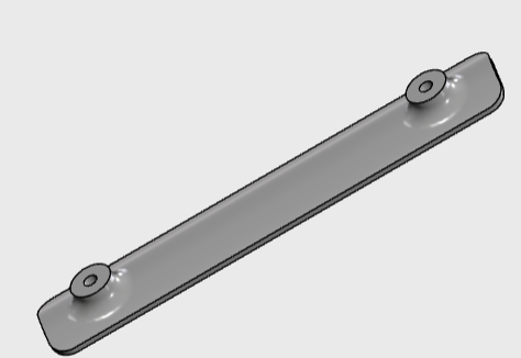
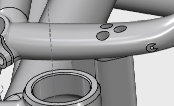
I also designed some water bottle bosses meant to be bonded on. These put all the thread height external to the tubes so I can avoid drilling (weakening) the tubes. Carbon tubing doesn’t like having holes drilled into it.
Lots more to go, but some ideas are firming up. I’ll likely use carbon seatstays, and titanium chainstays. With Ti I can gain a bunch of stiffness and durability to things like rockstrikes without going to large diameters that make it hard to fit around.
The goal here is a 120/120 trail/xc bike that can fit 2 bottles in the triangle on a small frame. SO far so good.
I am more or less done with a ‘rev 1’ of all structural components of this thing. I am moving on to stuff like cable guides now, and prototyping in plastic.
Lots of ‘hindsight 20-20’ kicking in at this stage. For instance- my selection of the Eskar adjustable dropouts has made brake clearance at chainstay a pain, and the chainstays seem less than optimal structurally. If I could start over I’d probably go with the paragon sliding setup. They were out of stock when this all started, and I rather like the Eskar dropouts in a bunch of ways. Switching to the paragon style sliders would probably shave ~150g off the weight, and make the whole package cleaner. I’ve already bought the Eskar setup, which I needed to measure/reverse engineer, so Eskar will remain!
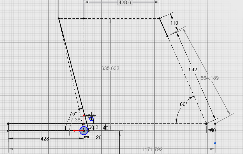
I am not sure I ever laid out the geometry- so here we go.
Wheel: 29
HTA: 66
Reach: 429
Effective TT: 571
front center: 747
Chain Stay: 428 (adjustable)
bb drop: 40
Head tube length: 110
effective seat tube angle: 77.4
wheelbase: 1172 (with 50mm offset and shortest CS)
Stack: 635 (?)
seatube length: 370
Note there is a mismatch in the stack between what I get in Linkage, vs what I measure in CAD. My stack (in CAD) seems to be ~20mm taller than most vaguely similar bikes, whereas the measurement in linkage is ‘normal’. If you see some obvious error in my sketch below… please advise.
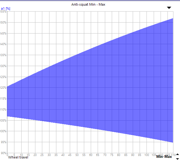
Here’s more ‘fun facts’ about the bike dealing with its suspension kinematic. Its a single pivot- not much excitement in there! I went this route to keep it simple, and it is.
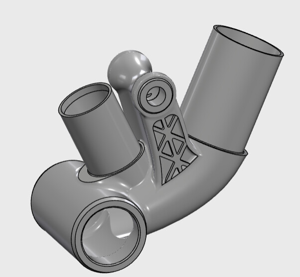
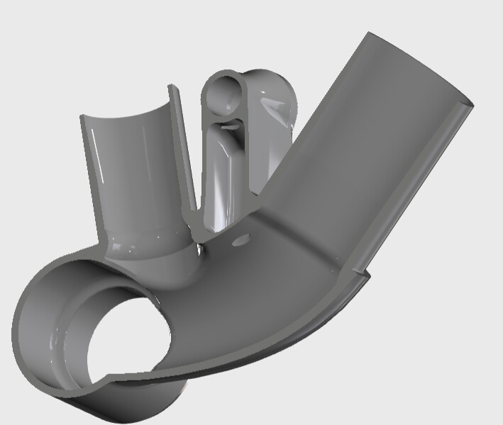
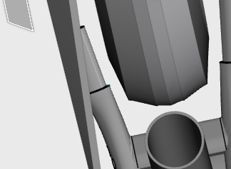
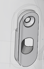
For bonus, here’s a couple of closeups of the yoke. Easily the most tortured an inelegant part of the bike. Definitely not going to win any awards for the design of this yoke. I am using a bolted-in yoke bridge to simplify construction.
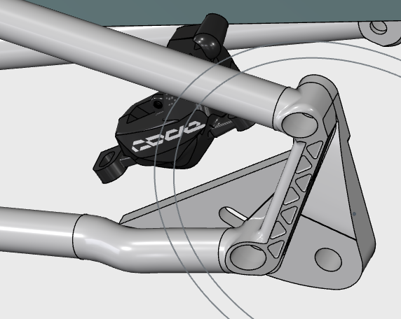
Cables will be internal through the front triangle, and external for the rear. To be honest I couldn’t figure out a way to get the rear brake internal without adding a ton of mass. The forward location of the brake mount makes it extra tricky. Dont mind the simple dropout CAD- that is just a ‘stay out’ zone.
is it possible you have laid out the fork offset parallel to the floor, rather than perpendicular to the steering axis?
its a good effort getting a complete pass done in cad, that takes alot of work, but id encourage you to stay in cad and address any fears or concerns you have in cad first; in my experience, moving from digital to physical reality will make those concerns worse, not better, and once you build it, you can start again, but you can’t really go back.
. have you thought more about bracing that lower pivot? i’m worried about where the forces go when you brake, especially into bumps.
I can’t remember exactly, but I think Linkage automatically includes some placeholder headsets in its measurements. I may be wrong, but I am always having to look up the stack of an EC44 headset lower, or an IS56 headset lower to make sure I include them in my CAD.
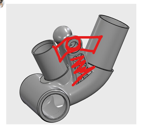
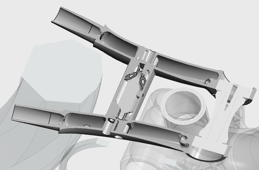
ahh, the suspension pivot. Ugly ain’t it? I think it should be strong enough, as its a fairly chunky box section, though load directions are not favorable to it! I am a little worried it could cause the main ‘body’ of the bottom bracket shell to flex/compress, and compromise the bond to the downtube. I think I’ll add a rib inside that structure to prevent the lug from 'flattening’ when loads through the main pivot push down on it.
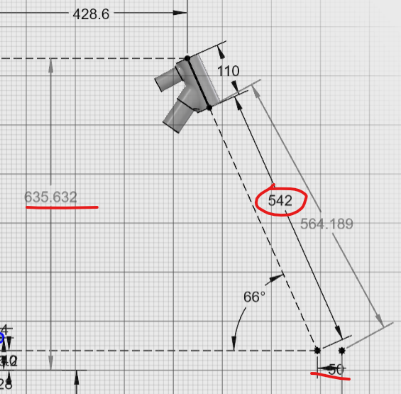
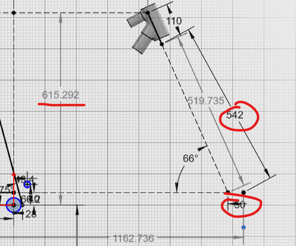
I double checked from your advice and I have the headset height values correct in Linkage. Fork A-C is 530 and I added 12mm for an EC44 lower cup. In CAD I’m using 542 for A-C (530+12). I’m still stumped on the stack values.
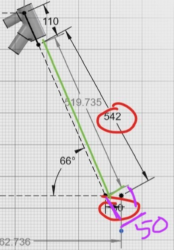
Here’s my one guess… I am using A-C from the centerline of the bottom of the headtube, intersecting with the line of the front wheel height, but NOT the axle position. I.e. it doesn’t account for fork offset. As I understand it, I am not supposed to use offset with this calc. Note I’ve found conflicting info on this from different sources.
If instead I use the A-C down to the actual front axel (accounting for offset), NOT following the centerline of the headtube axis, I get a lower stack. Neither number matches what linkage tells me (604mm).
Note I am OK with just having a 635mm stack. I just don’t like the discrepancy!
Your fork offset and axle position should be 90 degrees from the steering axis. Right now it looks like you have the fork offset parallel to the ground plane.
Good catch. Thank you. I had that wrong. Oddly I STILL don’t match the stack from linkage, but its much closer. If I hadn’t corrected this it would have left me with a HTA about 1 degree off, extended reach, ect,ect. I am going to have to overhaul my CAD to fix it. I guess that’s how the cookie crumbles. Thanks again.
I would ingnore the stack in linkage and go off your modelling. once you get you reach/stack location approximate in linkage and changes you make to the rear end will be 99.9% close enough to the same numbers etc. Only change you’ll really get if you track the reach/stack location accurately is in front and rear weight balance.. Though will admity I haven’t played around with that part of it much as I didn’t see any meaningful changes when I moved the reach back and forth by 10mm to my suspension graphs.
Also the reach and stack is measured from the centre of the top of teh ehad tube. Not from the top tube head tube centreline intersect.
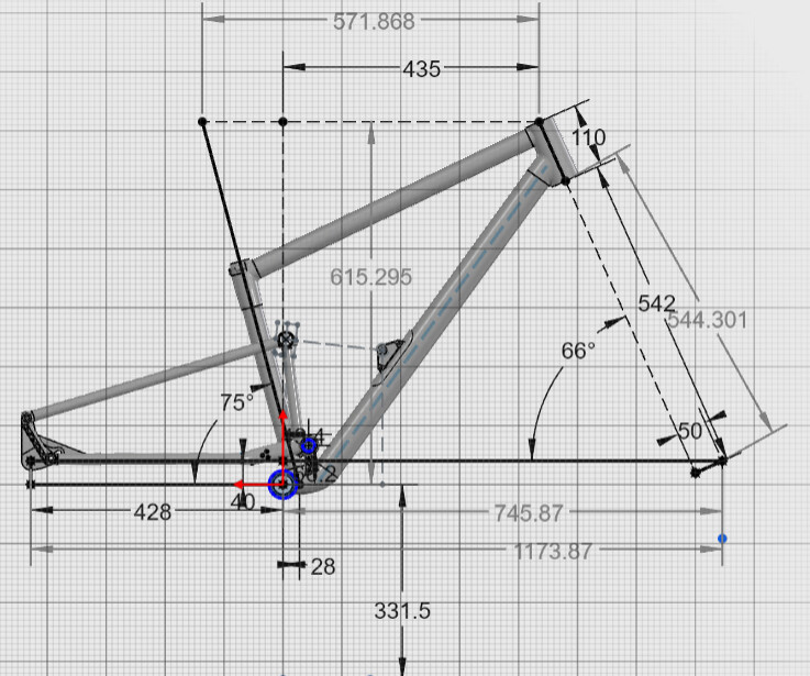
Thanks to the excellent advice on this forum, I was able to find and correct a serious error in my frame geo. If this hadn’t been caught I would have had a rather steep HTA and longer reach than intended. Here’s the frame after corrections!
Getting this all straightened out took alot of re-doing modeling of the heattube, bottom bracket, and seattube lugs, but honestly the effort gave me the chance to fix a bunch of smaller issues as well!
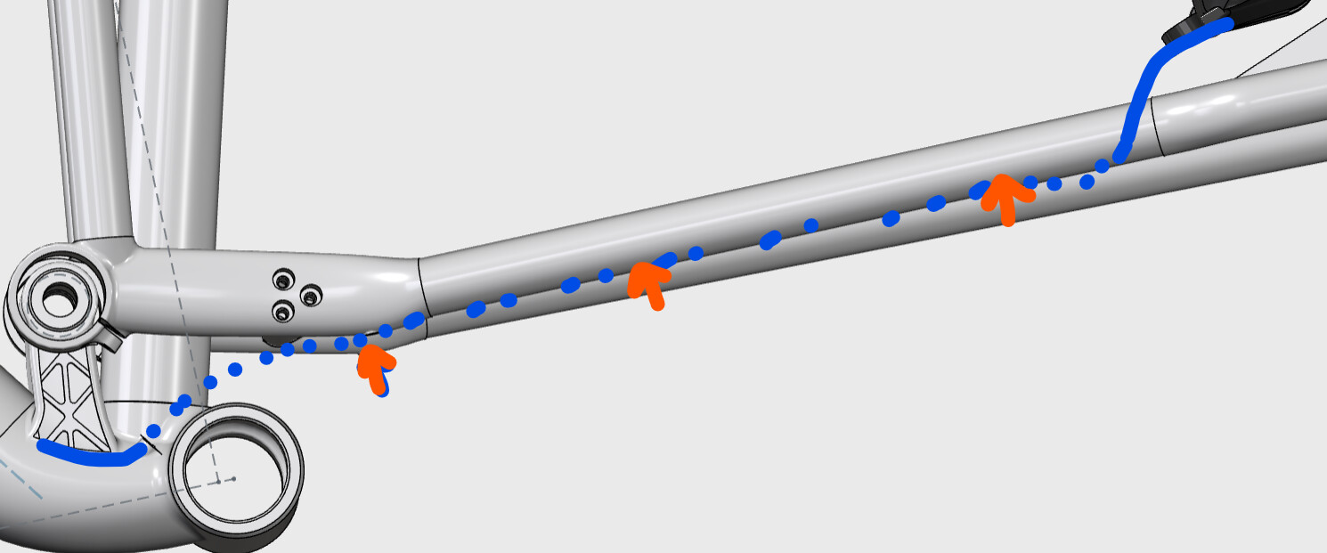
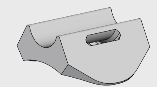
I’m sorting out the external portion of the cable routing, exiting from the BB lug, and then using some external guides bolted to the yoke, and bonded to the chainstay:
Absolutely. I’ve modelled stuff thinking I was ready to order then spend another two weeks completely rebuilding everything from scratch. They get cleaner each time.