@colinreay where’s that tandem though?
3 Likes
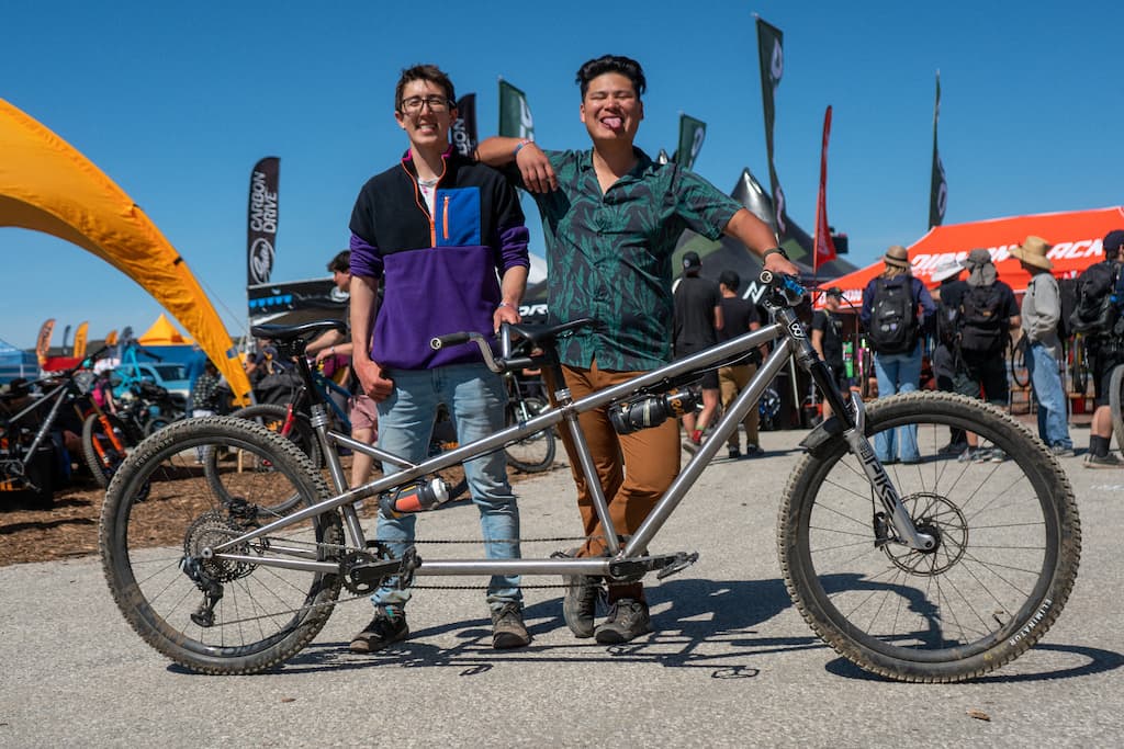
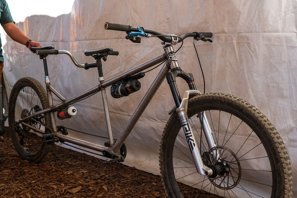
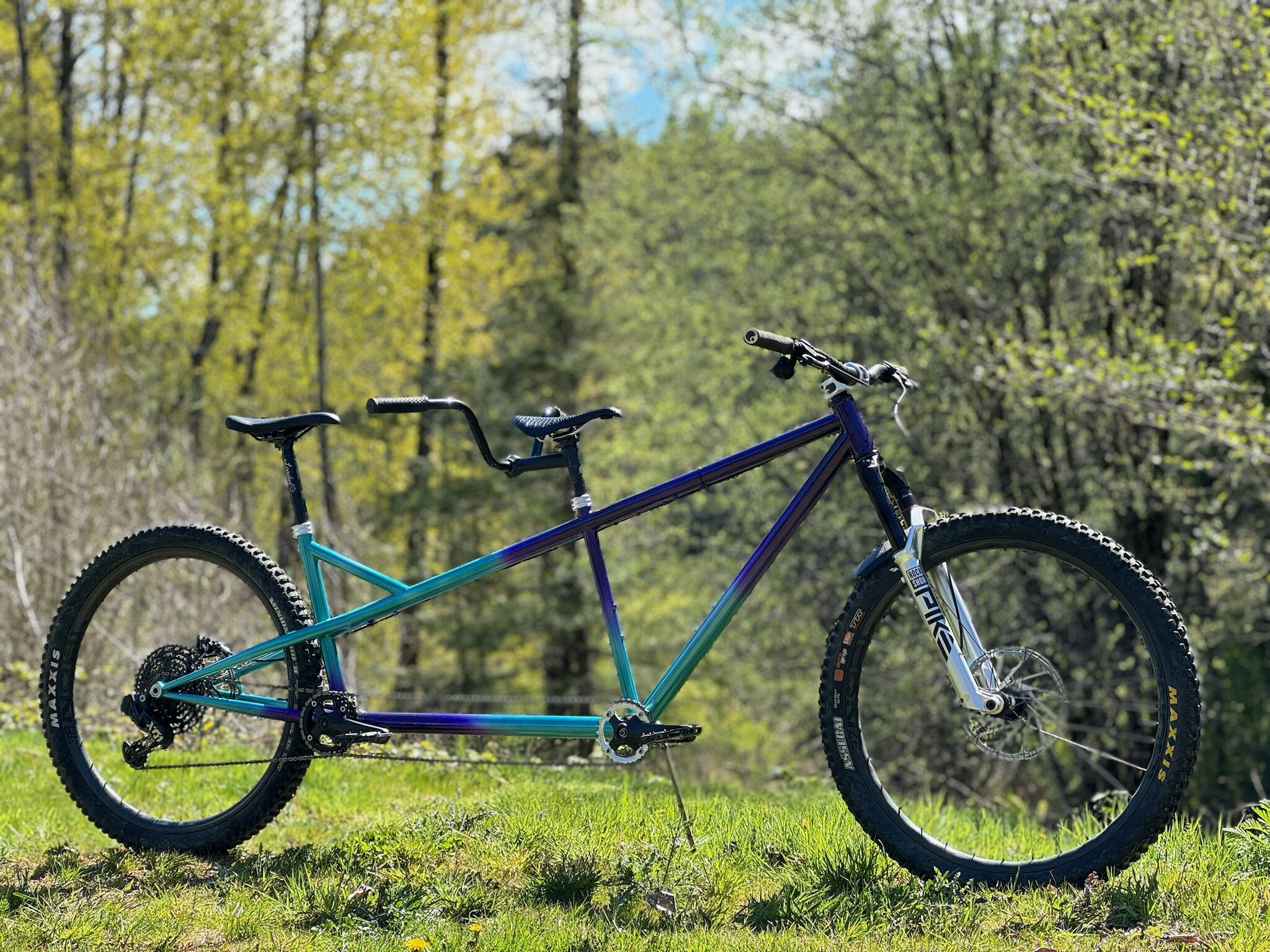
Another bike to share - my friend Kevin and I built an mtb tandem to race in the 40K Fuego XC at Sea Otter. We started the frame the Monday before the event and took our first test ride Thursday night. We harvested the parts from Kevin’s personal mtb and AXS drivetrain from his shop’s demo bike. Additionally, I ended up making a stem and some Engin-inspired seat collars. We had to overcome a lot of mechanical issues; some of the highlights include:
-
Reverse pedal threads - our pedals kept backing out! Come race day, we ended up cross-threading the pedals hard enough into the cranks to act as a form of loctite. They lasted the whole course!
-
Asymmetric square taper bottom bracket. The wide BB I bought has a 3mm drive-side offset. I spent a lot of my Thursday night making an offset T47-BSA adapter with funky drive spline to center the rear cranks.
-
We cooked our rear mechanical-hydraulic hybrid caliper while trying to bed the brake rotor in, which rendered the brake almost inoperable. Calvin and Truman from Park Tool came to our rescue on Saturday, and Paul’s components donated a Klamper lever to the cause.
This was Kevin’s first time building a bike or welding, and he did an amazing job. The bike felt great, and we finished second overall, despite starting 10 minutes late after getting lost on our way to the start line. This was one of the best, most action-packed weeks of my life, and many good memories were made!
Here are some photos of the rig!
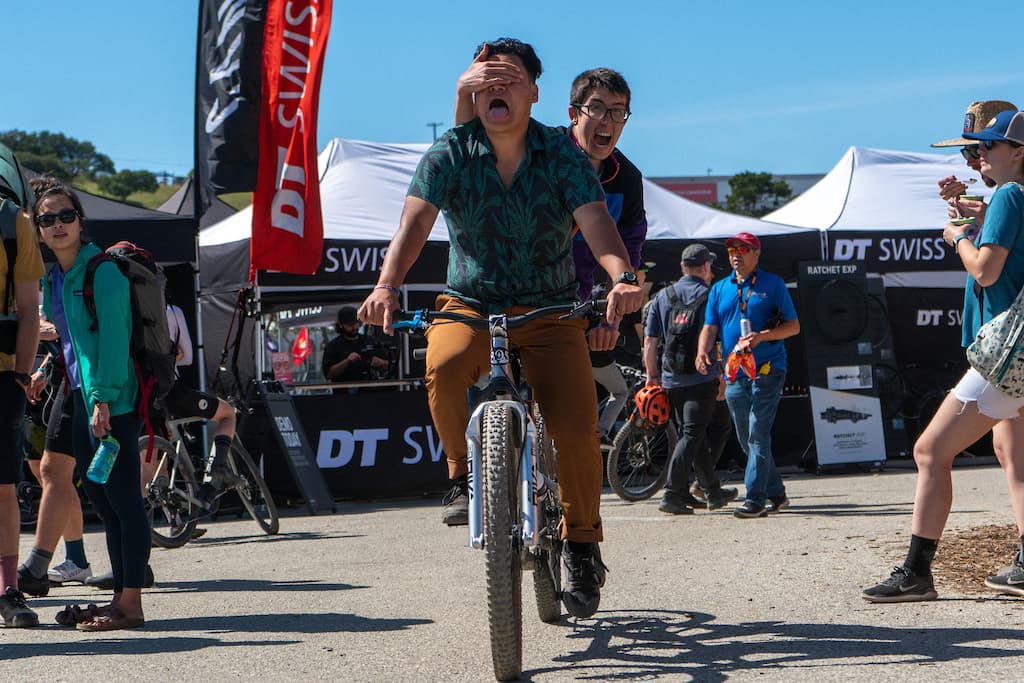
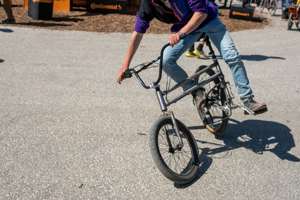
Some shenanigans with the swing bike:
13 Likes
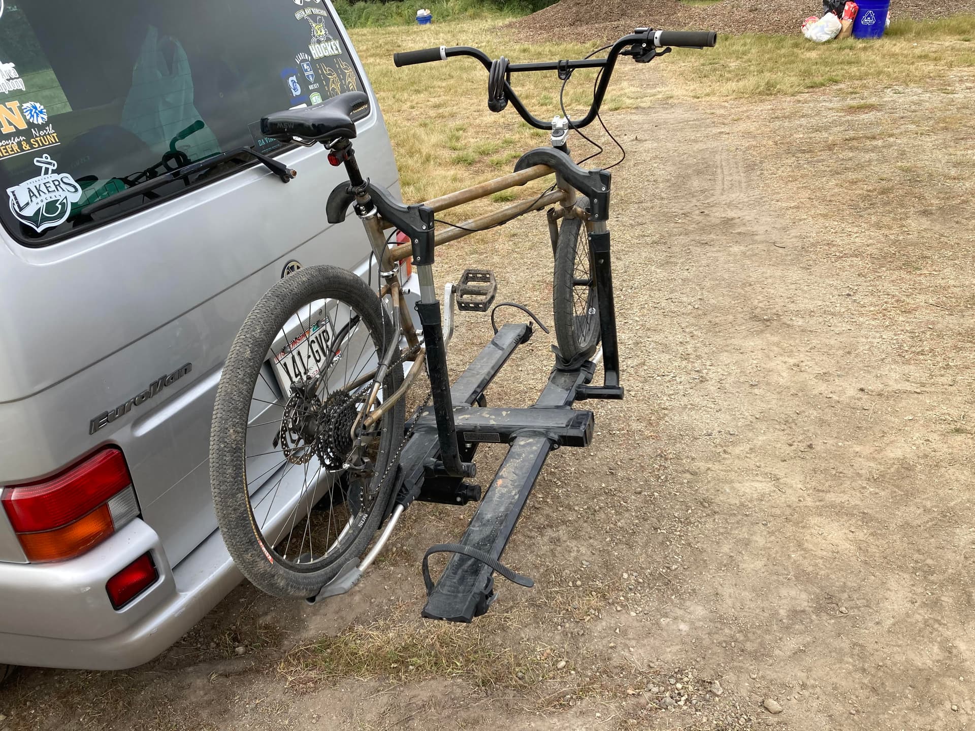
Loved seeing the pinkbike feature on the tandem! Great hustle getting it together in time! Also, sweet eurovan hauling the swing bike👌
2 Likes
Thanks for bringing your bikes by the booth, I love that you guys raced that tandem, so rad. Keep up the great work!
3 Likes
Wow. Next level stuff. This makes me so happy.
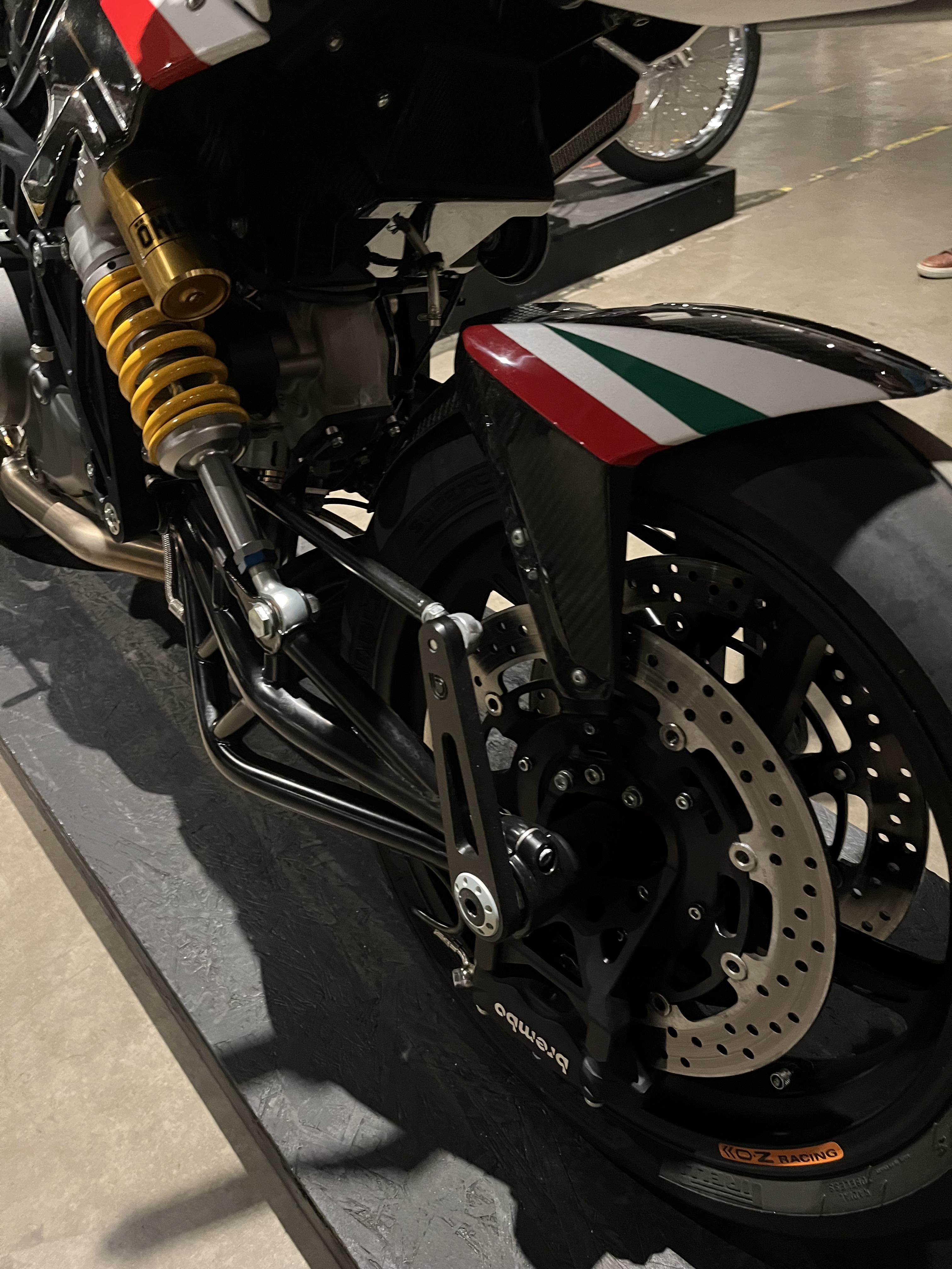
I really like the center steer hub. I was at the handbuilt motorcycle show in Austin last week and I actually saw the Bimota you took your inspiration from. I stared at that bike for a long, long time.
When I saw the pic of your hub, I instantly thought of the Bimota— and then I kept reading and realized why it was similar. Keep up the awesome work.
3 Likes
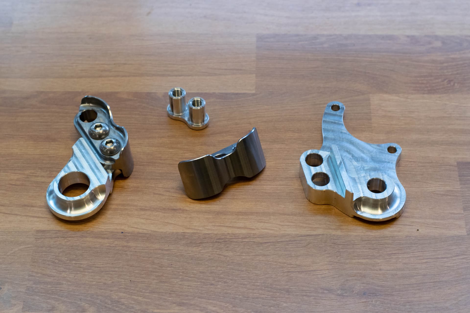
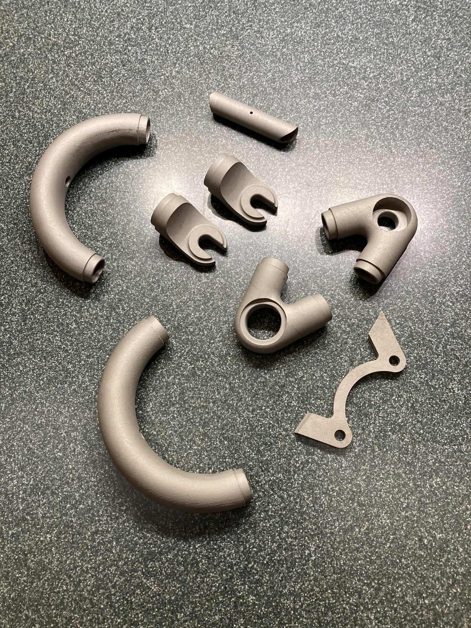
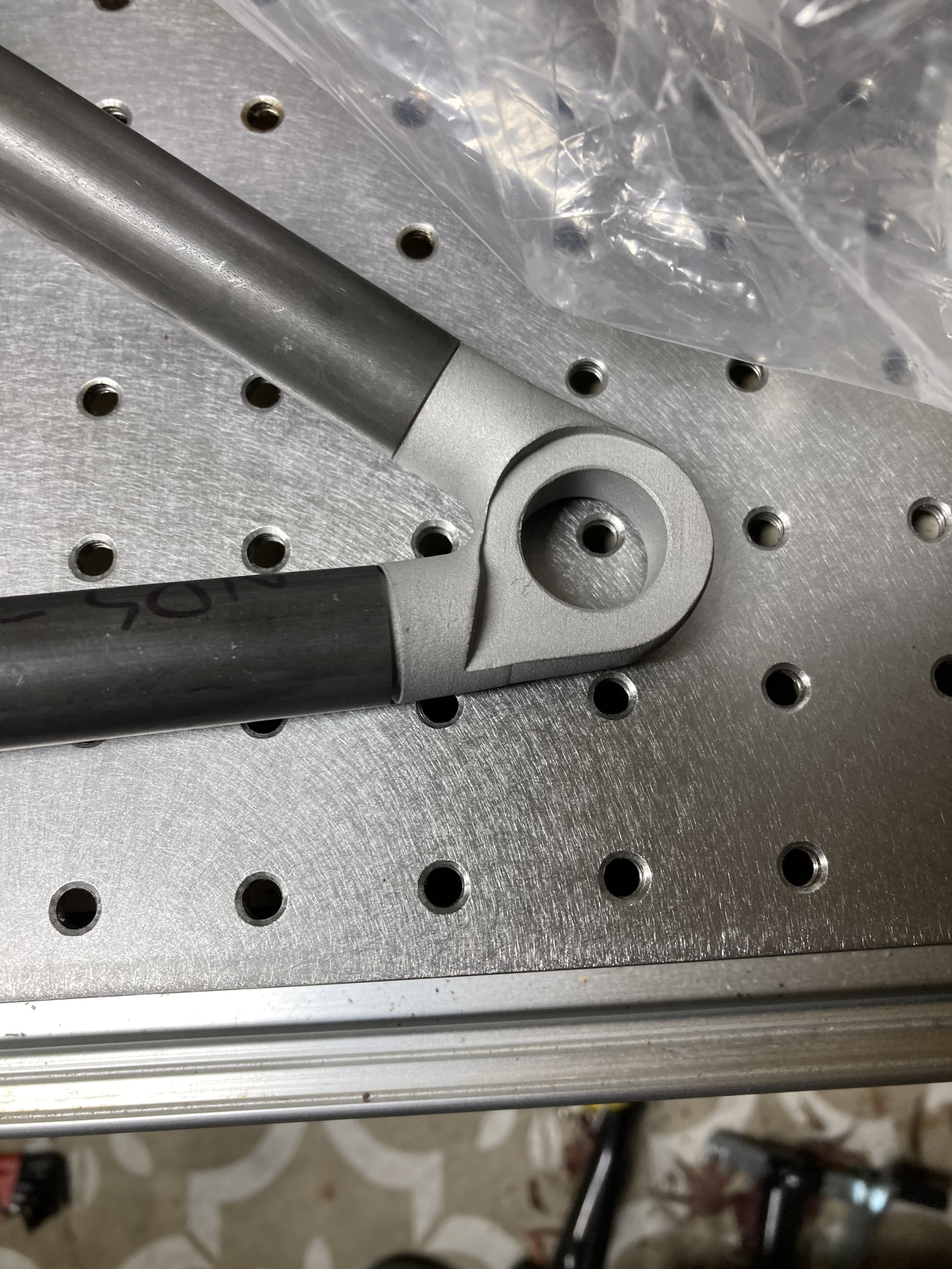
Here are a couple of parts I’ve made for an upcoming full-suspension build with my friend! The bike will be a DW-style with swappable pivot points to quickly convert between a 140mm trail-oriented layout and 178mm enduro layout.
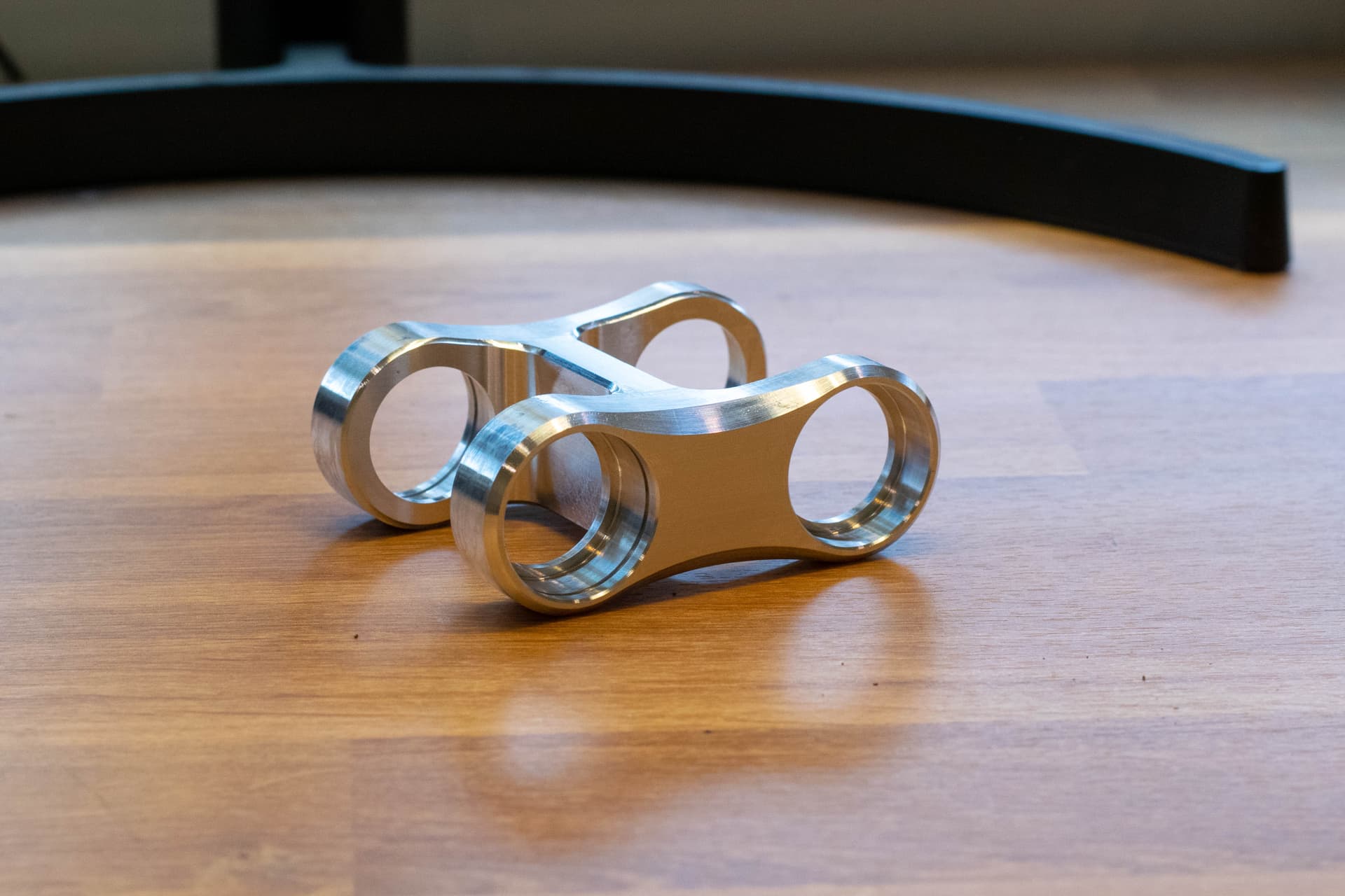
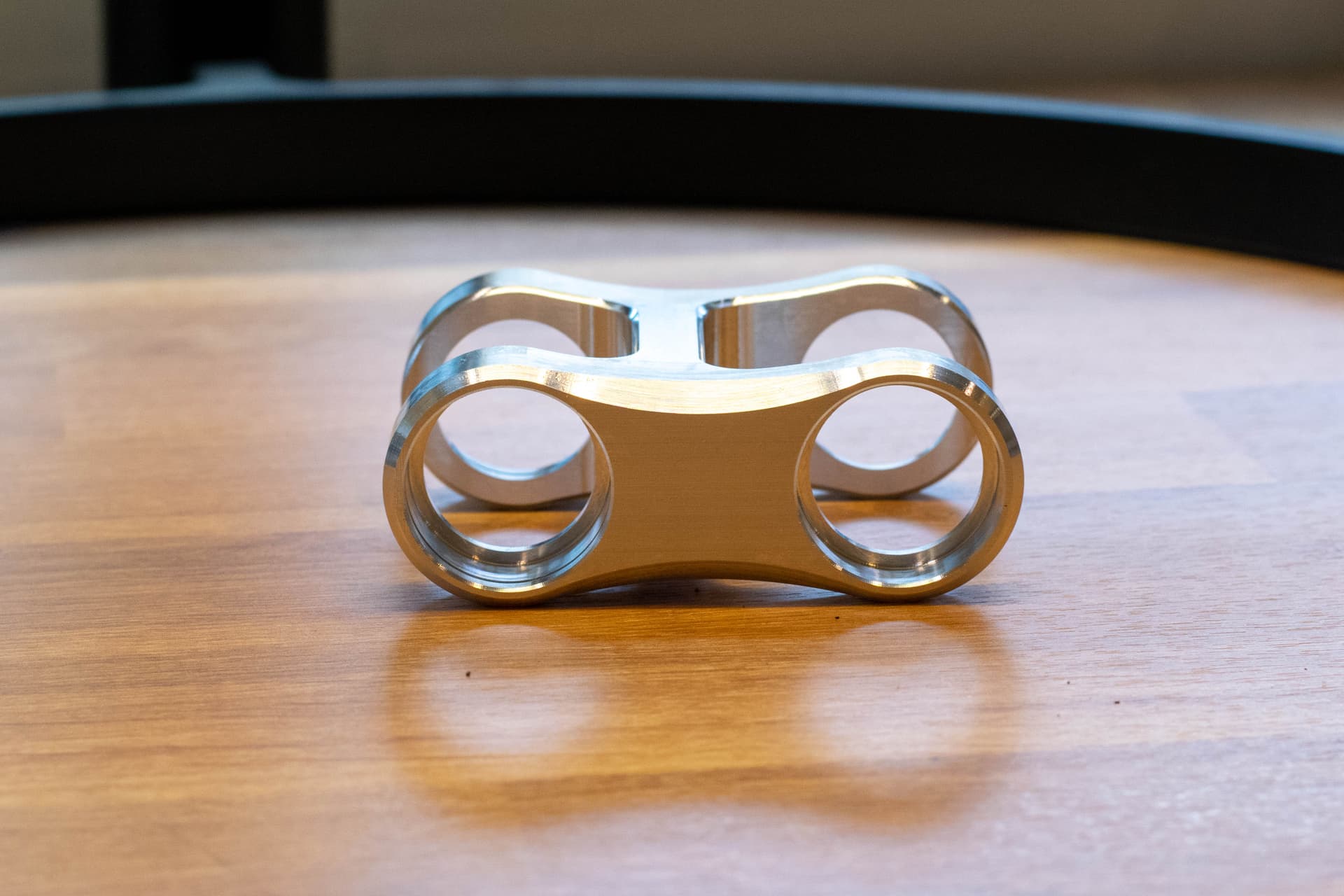
Lower suspension link.
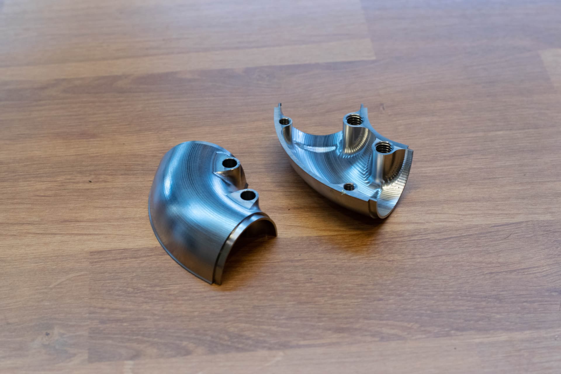
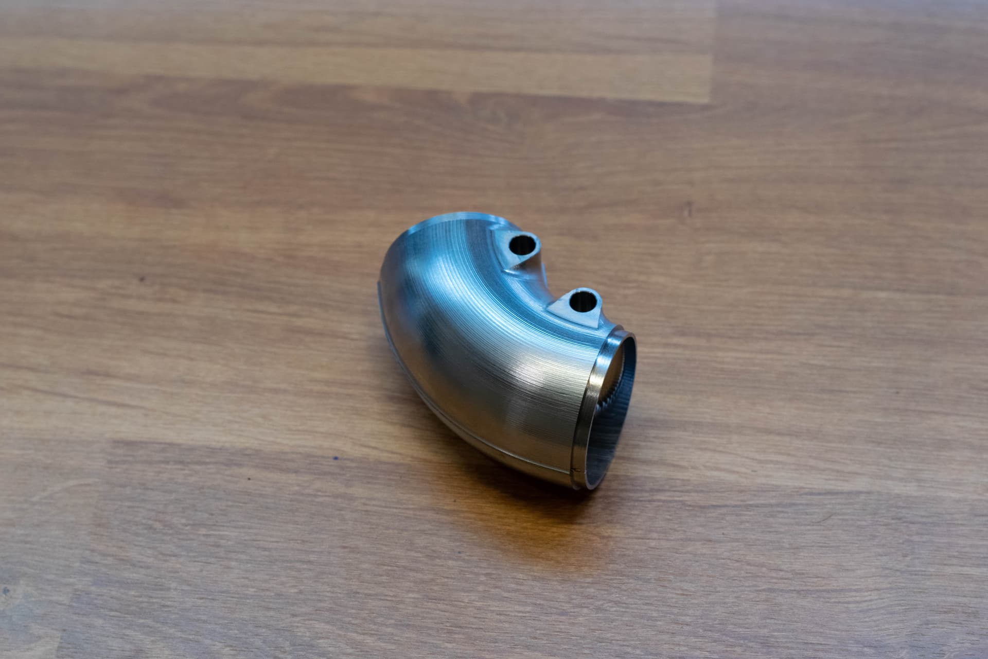
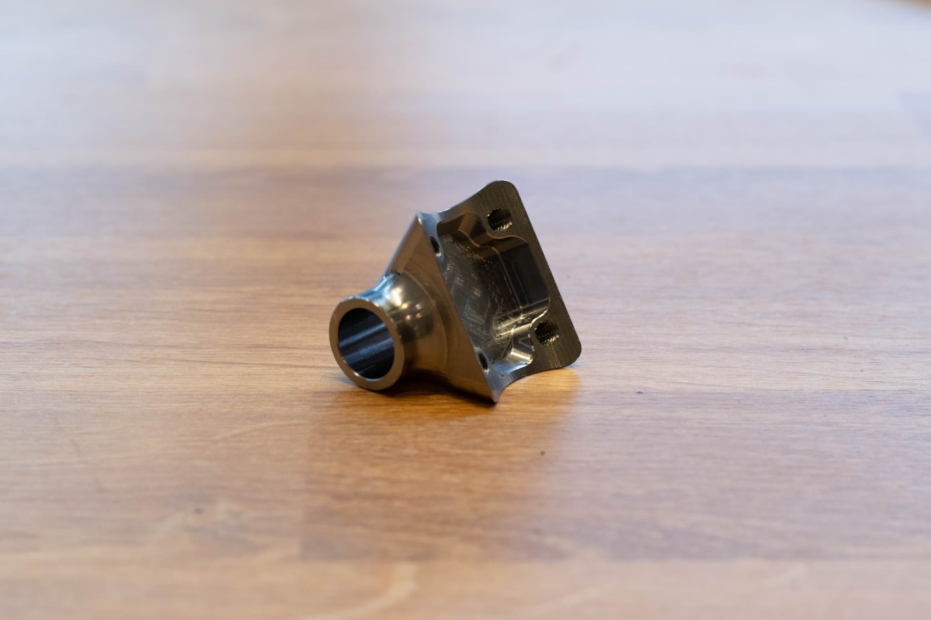
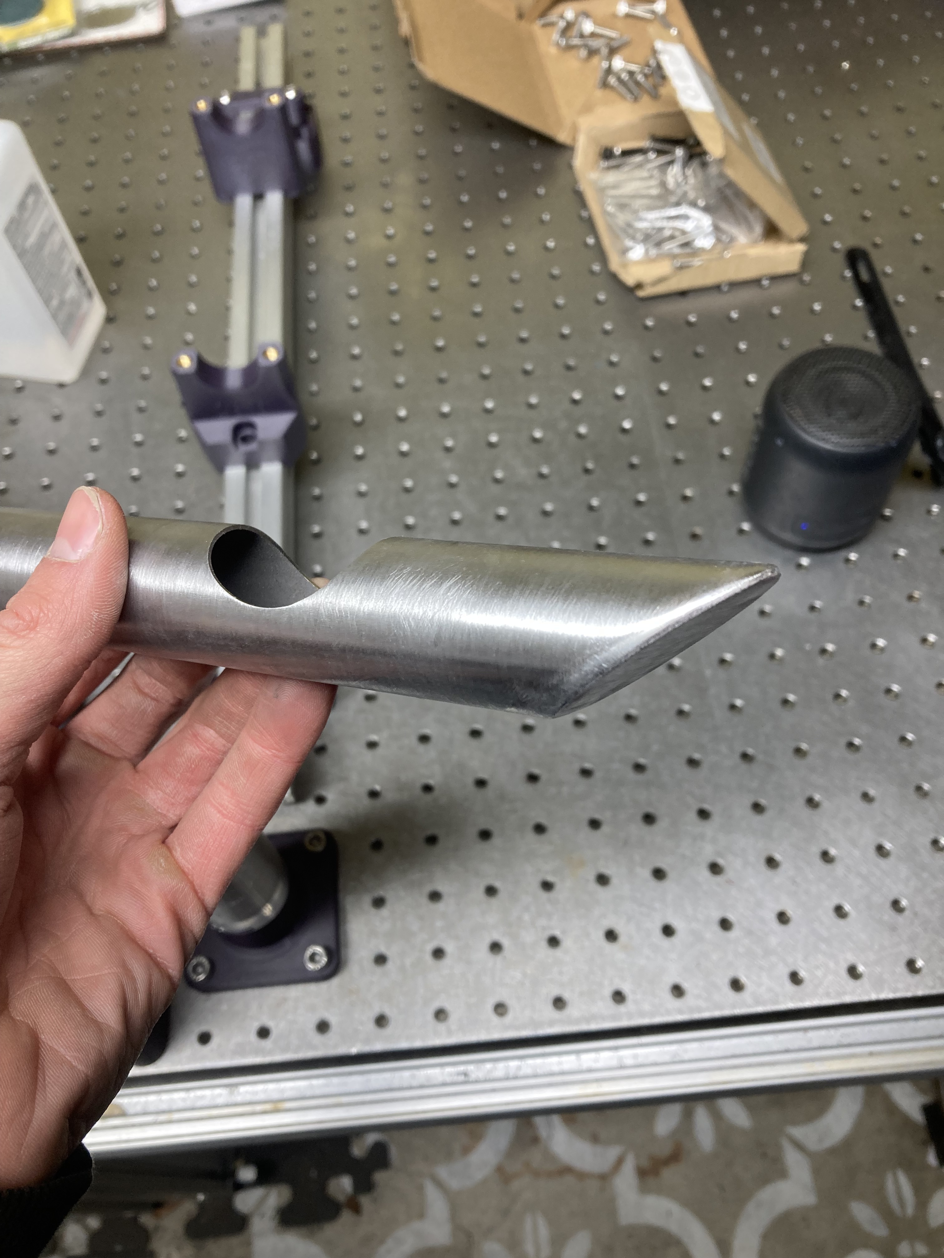
Downtube bend (needed an extremely tight radius) with integrated shock mounting points. Both ends are slightly tapered to compensate for angular misalignment. Thanks @Neuhaus_Metalworks for the tip!
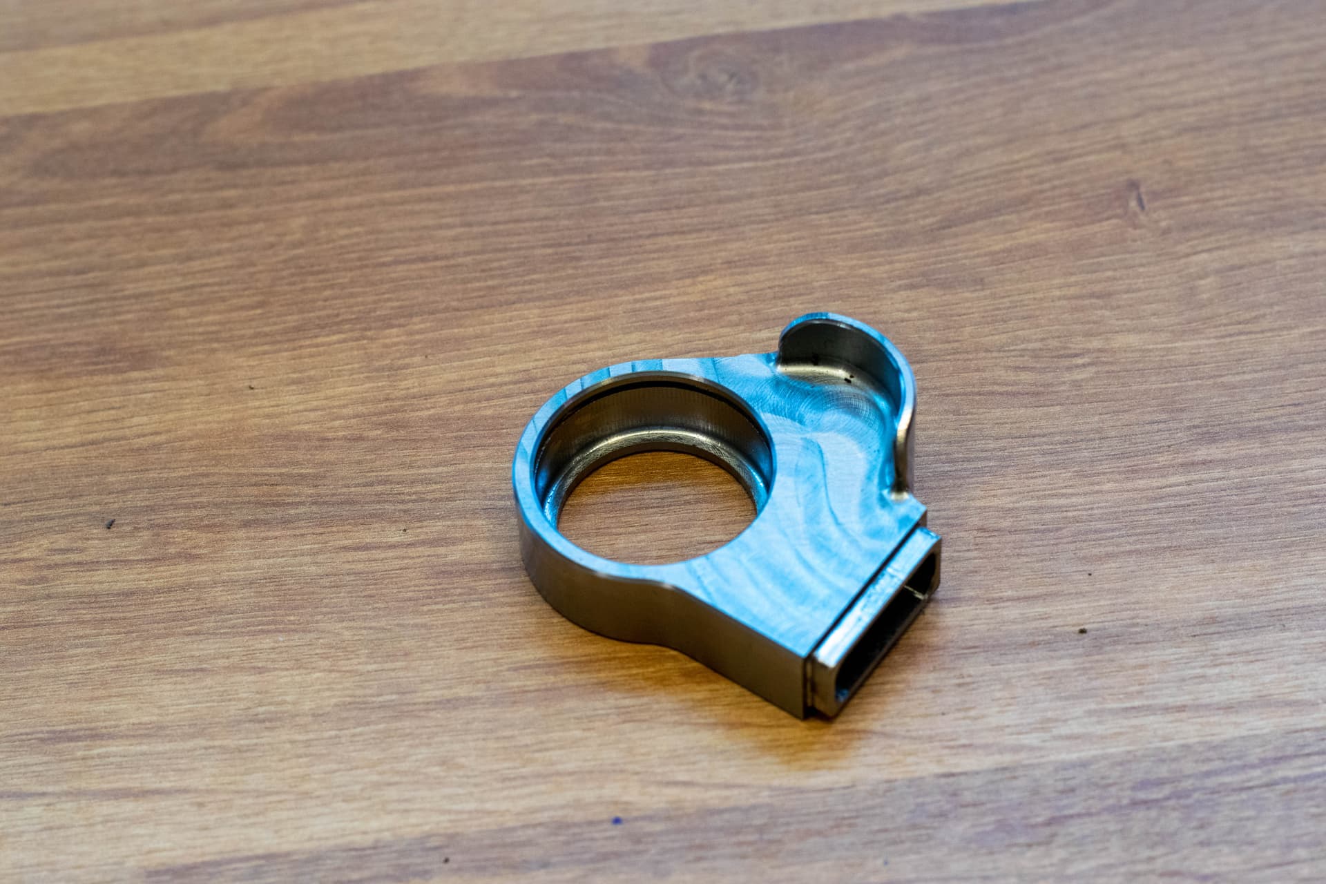
Upper bearing mount. Integrated snap ring groove and rectangular tube connector.
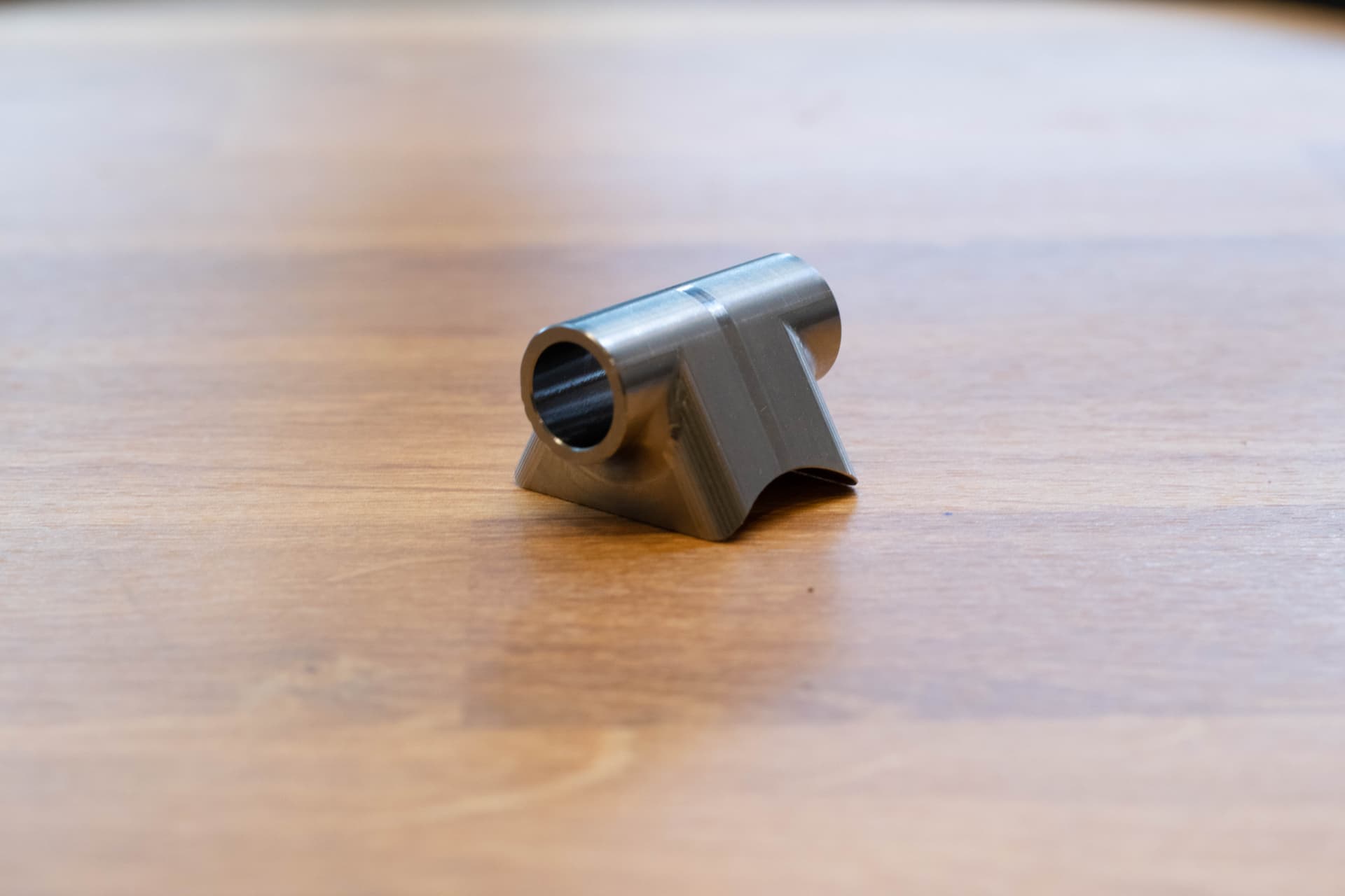
Pre-mitered rocker mount. The threads on the bottom side are just for workholding!
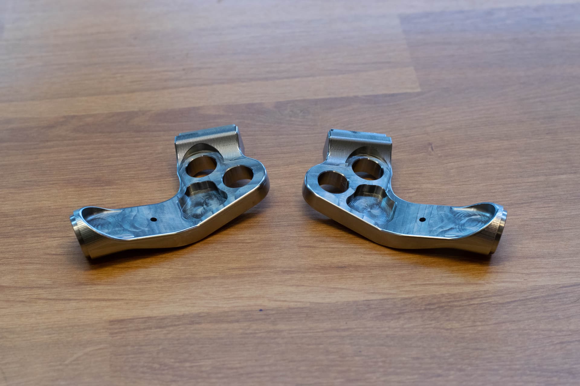
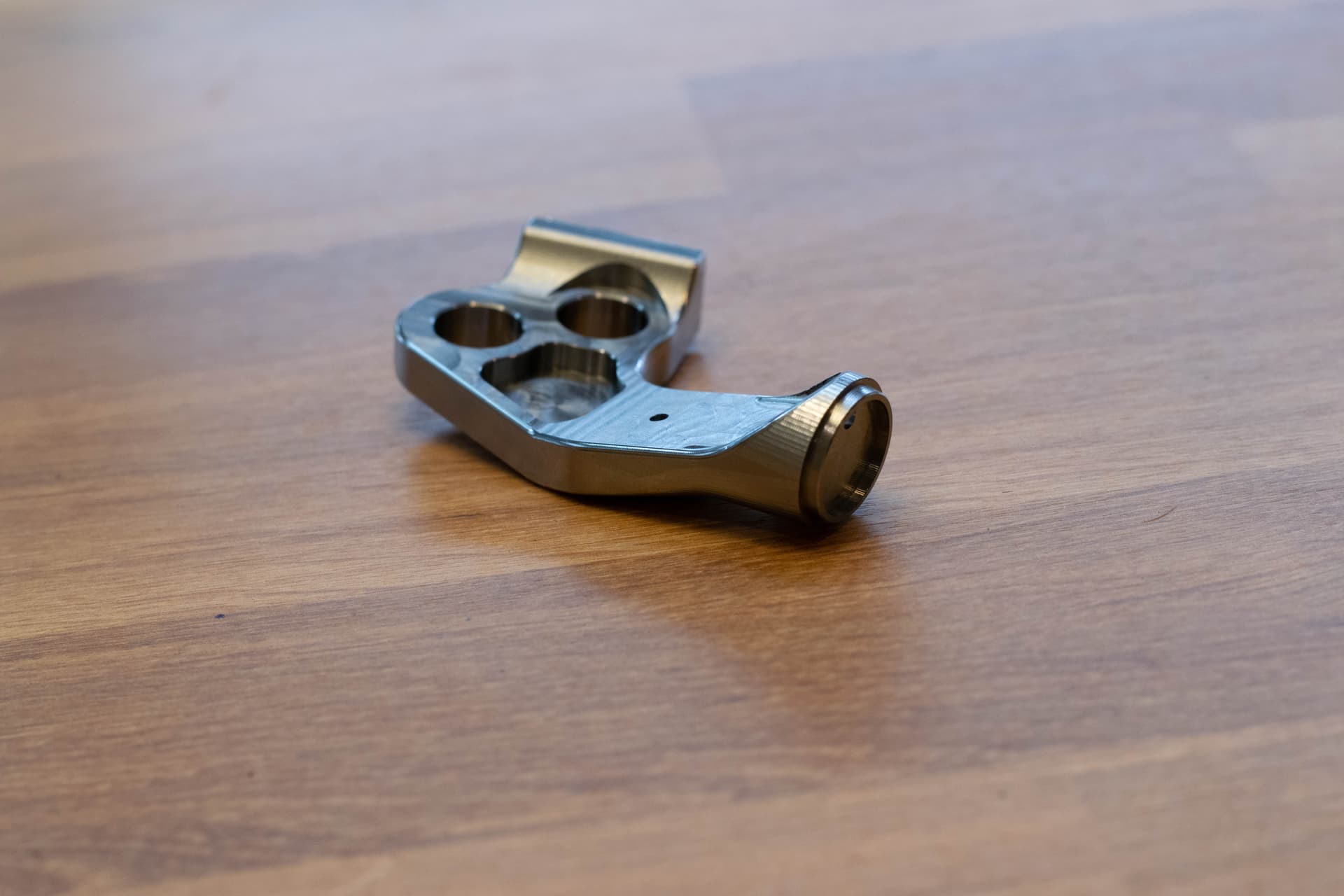
Lower rear triangle “yoke” pieces. Premitered on two ends - I’m really happy with how well the surfacing turned out.
Indexable UDH dropouts.
11 Likes
Nice work!
2 Likes
Wow good stuff. This sounds like an awesome build, where did you get your parts machined?
2 Likes
Amazing stuff right there. I need friends like you and @Daniel_Y
2 Likes
Thanks! I do all the CAM + machining myself. Through my university, I have access to several CNC machines and am able to use them for personal projects - it’s an amazing opportunity!
3 Likes
Hey everyone!
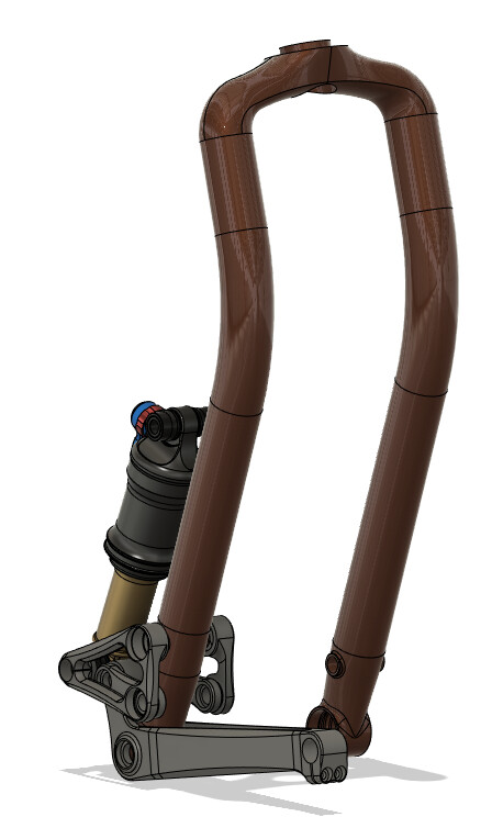
I wanted to share some early progress on a linkage fork. I am not sure what the future of the project is - I already have too many things going on!
Motivation: Create a cargo fork, similar to the Crust Clydesdale, with suspension. I also wanted to decouple the cargo load from the unsprung mass of the wheel assembly.
Design: After a lot of sketching, I decided that a leading arm layout made the most sense. Rocksled suspension has done some great work in this area.
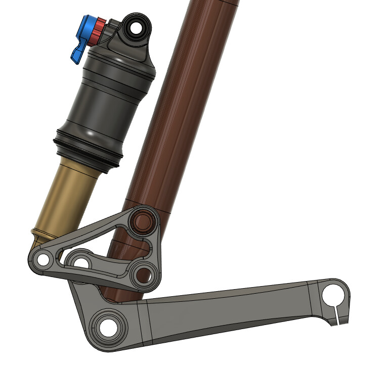
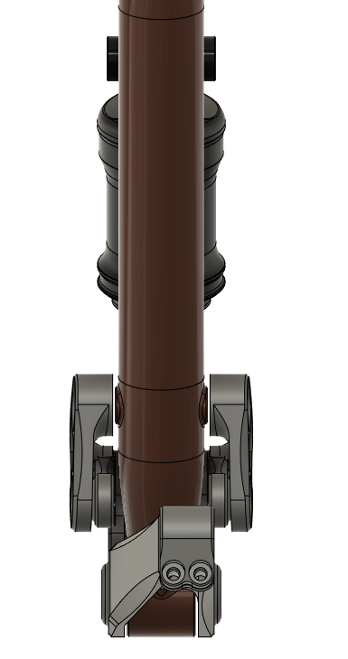
Suspension linkage: I drew up a linkage-driven mechanism with high amounts of progressivity. Some photos are attached below.
Modeling:
This is the part that I’m most excited about. When making design changes, I wanted a fast, accurate way to determine my leverage curve, trail, wheelbase, and anti-rise. The following info is pretty math-y, but something I find fascinating.
Context:
There are a lot of different ways to do kinematic analysis. When I made my first mountain bike, I created a program using vector loops to calculate anti-rise, squat, and axle path (here’s a video of the program applied to different linkages) https://www.youtube.com/watch?v=v4InvZJIKGk. However, the vector loop method I used was overly complicated and inefficient. Each vector was solved independently, making for messy code and an overwhelming amount of variables.
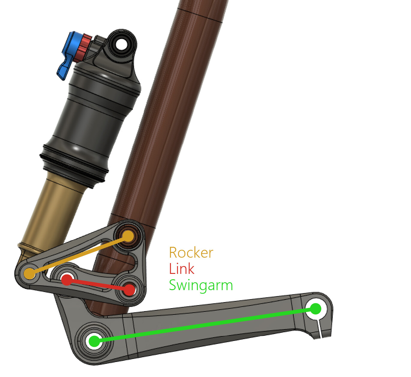
I changed my approach for this project. Now, I store a single rotation angle for each rigid body in the suspension mechanism. Therefore, I can determine the location of any point on a body (in this case, the swingarm and rocker) by using a transformation matrix and vector. The link connecting the swingarm and rocker is a constant length, and the angle of the swingarm is known, which makes it straightforward to solve for the rocker rotation angle numerically.
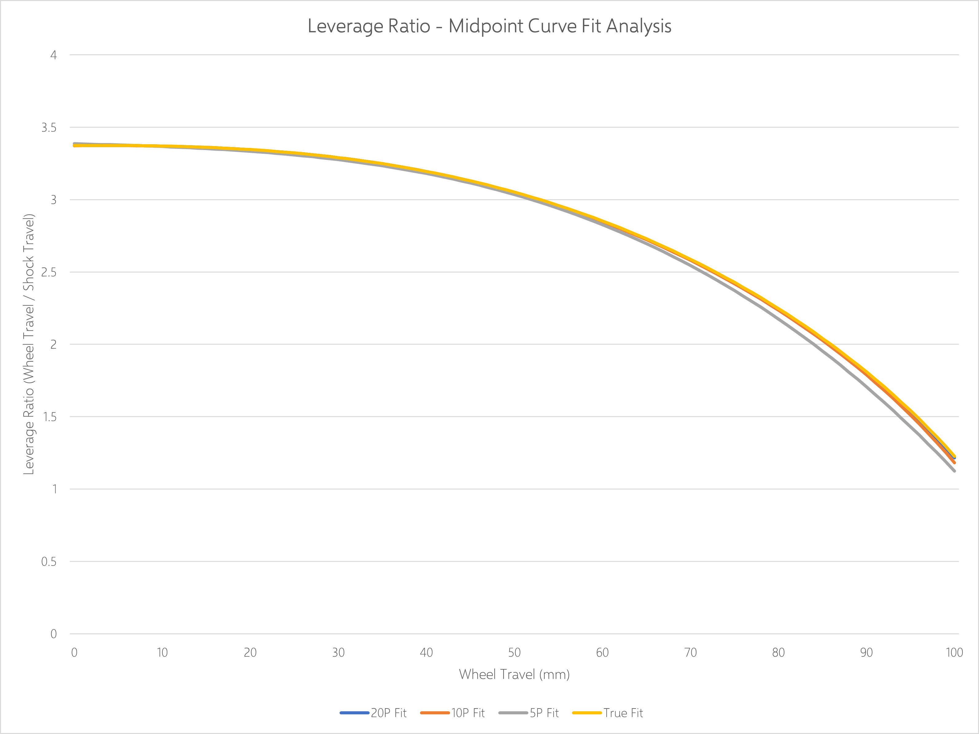
Right now, I solve for the system state at 10 different points across the suspension travel. I then apply a curve fit to the data to predict the suspension performance at any point in the travel. I tried applying a curve fit to 5 points, 10 points, 20 points, and 200 points. From the graph below, we can see that there is virtually no difference between 10, 20, and 200 points (called true fit). Thus, the 10-point fit is a good combination of accuracy and computational performance.
Modeling takeaways:
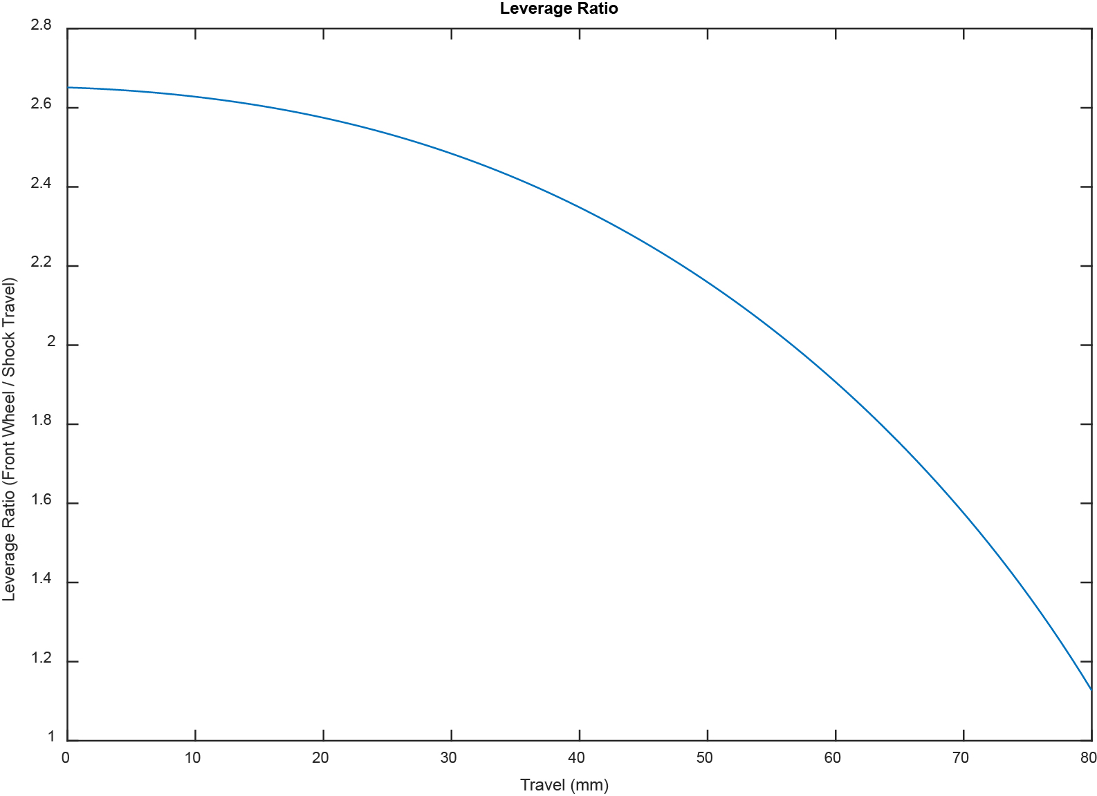
The first thing I solve for is leverage ratio. An example graph is shown below:
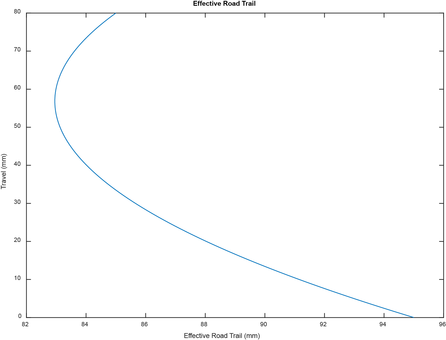
The next thing I solve for is effective road trail at each point in the travel. I expect the fork to be installed on a hardtail, so any suspension movement corresponds to a forward pitch of the bike. I calculate the trail by rotating the entire system about the rear wheel by the pitch angle and determining the delta between the contact patch and steering axis/road intersection point.
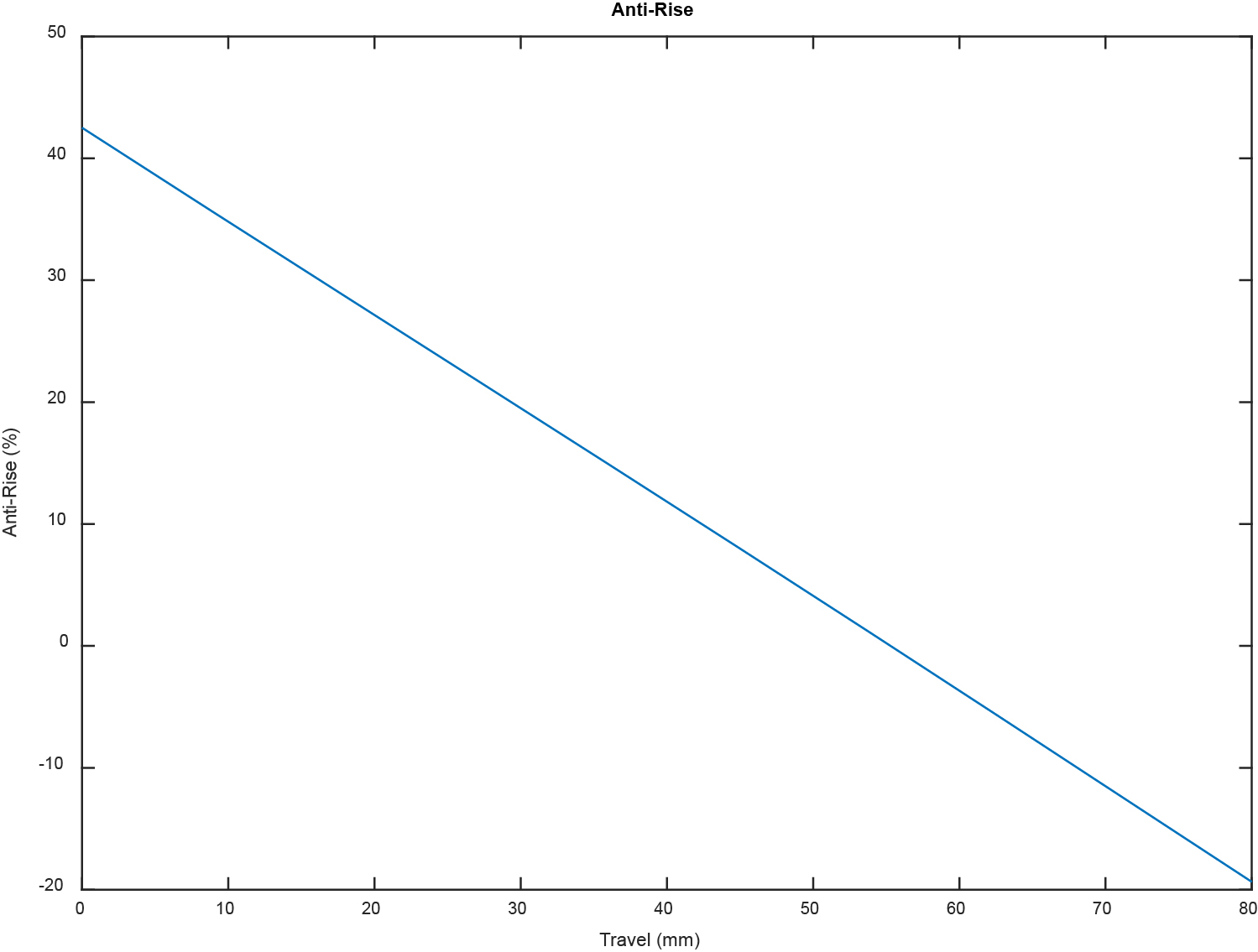
The third calculation is anti-rise. I’m following Tony Foale’s methodology to calculate this and am using a 4-bar brake mechanism. I’m not really sure what the target values are here. For example, telescoping forks have large amount of negative anti-squat. This calculation still needs work. I’m not currently accounting for the forward pitch of the bike/system; this is the next change I’m making to my program.
This was a fun weekend project. I look forward to integrating more kinematic analysis into future projects to help inform my design decisions.
15 Likes
Damn you build bikes faster than I cut a few tubes and weld them ![]()
1 Like
I’ve been tinkering around in Matlab to create a robust program for suspension analysis (motivated by Peter Verdone’s latest post and my rough linkage fork concept).
So far, I have the tool working well for 4-bar linkages where the shock is connected to the swingarm or upper rocker, and a linkage-driven single pivot.
One of the trickiest aspects of designing the tool is determining how to “drive” the model. Usually, this is done by changing your shock length or moving the rear axle upwards. After reading Peter’s post, I tried driving the model using a shock. However, I think using the rear axle as the model driver is far more flexible and allows you to decouple your shock linkage from the linkage defining your rear wheel path, anti-squat, anti-rise, etc.
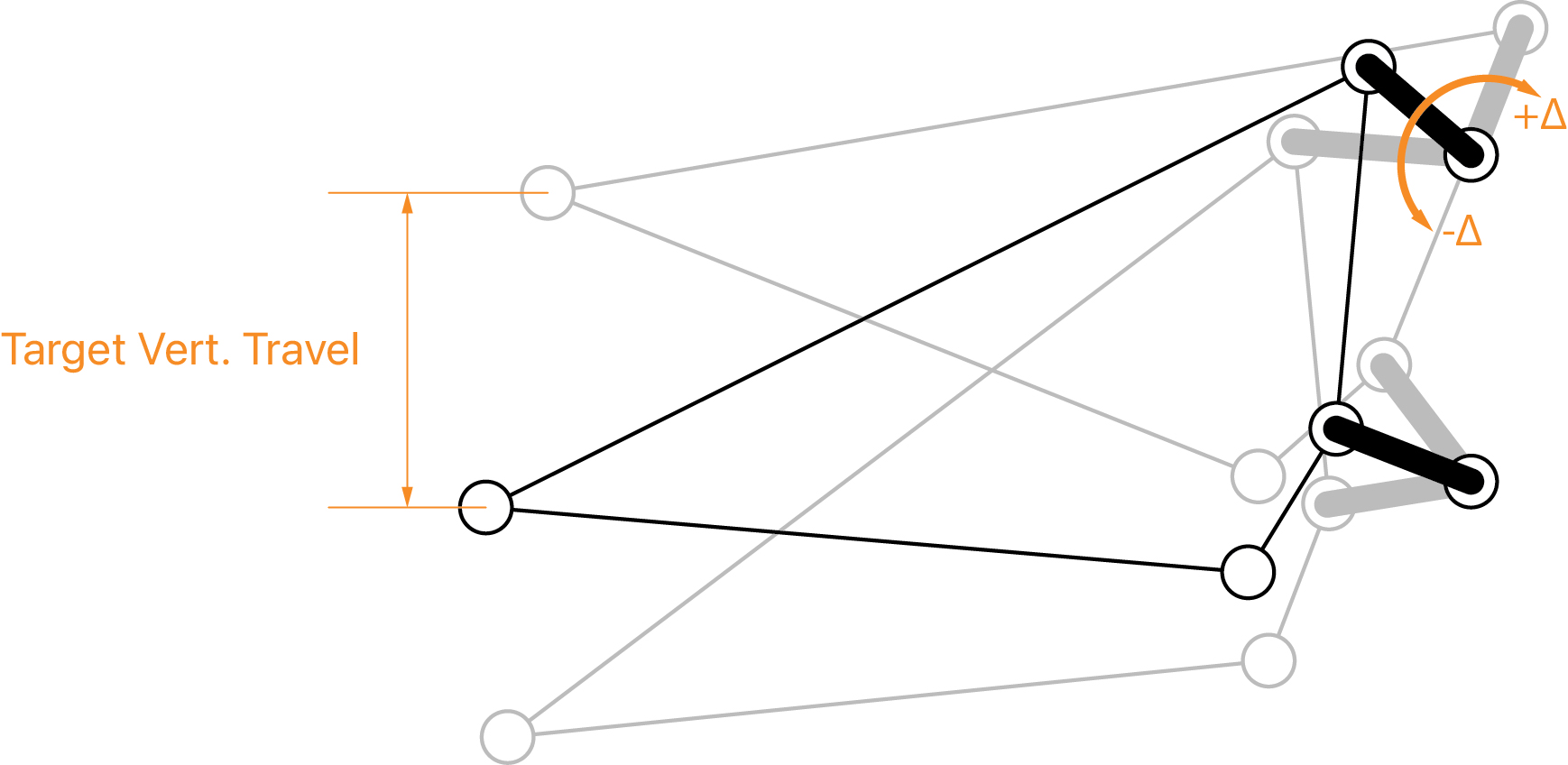
I’m using a small “angle-sweep” method to calculate the linkage state at 1000x points throughout the travel range (defined by vertical rear wheel displacement). In the angle sweep method, one of the suspension links is rotated in very small increments on either side of a nominal target. At each increment, the suspension system’s state is calculated until the ∆ between a target and actual value (in this case, vertical wheel position) falls below a certain threshold. I do this at each of the 1000x points. I really like this method since it allows for short links, long links, co-rotating, and counter-rotating scenarios. I created a graphic to try to visually explain this.
Animations!
I set up my tool to output .csv files with specific point locations and values at each point in travel. This makes it easy to animate the mechanism in After Effects using its Javascript code language. After Effects even automatically updates the animation every time you generate data for a new mechanism!
Here are some early examples below:
DW Link
VPP
CBF
ABP

Horst Link
Single-Pivot Linkage Driven
Still a lot of work to go. My next step is to animate graphs that are automatically generated/scaled for each mechanism.
11 Likes
Very cool work! I have spent a bit too much time trying to reverse engineer a good CBF system. I was just doing spreadsheets and Linkage. Looks great. Do you know how accurate that setup for the Lithium is?
Thanks, Pax!
I got the initial vectors/points for the bike from Linkage. I feel pretty confident in the program output based on those points, but I’d want a high-res 2D drawing of the bike to get the most accurate setup possible.
Ultimately, I think the modeling/animation setup I have is best used for illustration purposes of existing/new linkages (similar to Trail POV’s channel).
I was able to get something very similar to the CBF system purely in CAD. I sketched out the rear suspension linkage without fully constraining either link. I then drew a line between the rear axle and instant center of rotation at sag, 0, and full compression. Then, I made all three of those lines tangent to the front chainring; I did this to try to force the center of curvature to always be at the chainring/chain contact point.
If I recall, the model was super unstable. All of the links would blow up if you tried to drag around unconstrained points, so I resorted to adding temporary dimensions / fixing various points as I tuned (i.e. dragged points) the linkage. I ultimately ended up with a linkage that was a near carbon copy of the Revel setup. lol
2 Likes
That’s awesome, really solid work. The breadth of your skill set is tremendous .Getting all the pivots to play nice with the center of curvature was the hardest part for me. Hopefully I’ll get a physical prototype and see how off I am in real life haha.
2 Likes
Trying a new approach for modeling… I’m now tracking the change in pitch of the bike based on front and rear wheel travel (controlled independently). Above is a quick animation of a flex stay single pivot where the frame is centered on the ground contact patches.
14 Likes
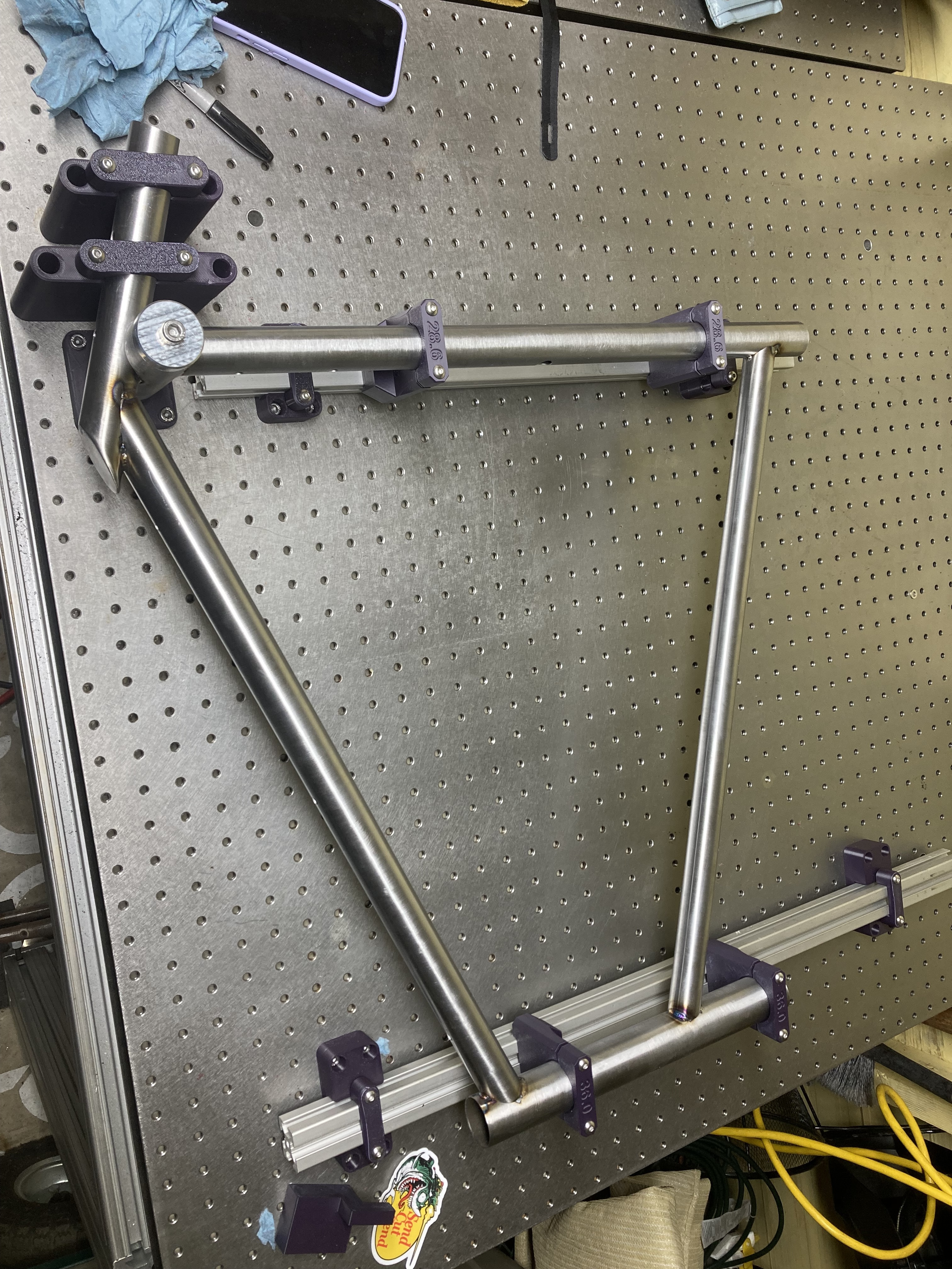
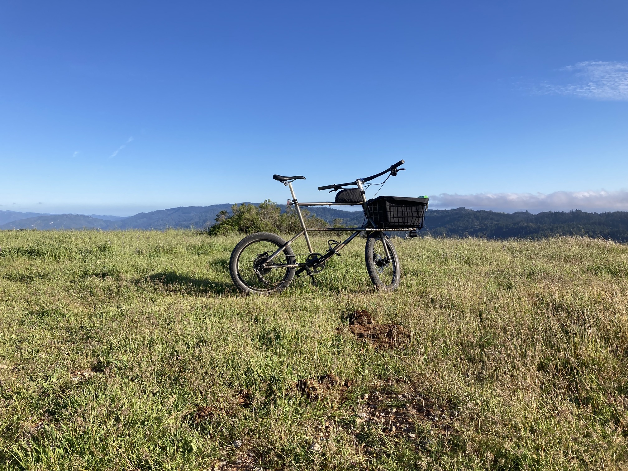
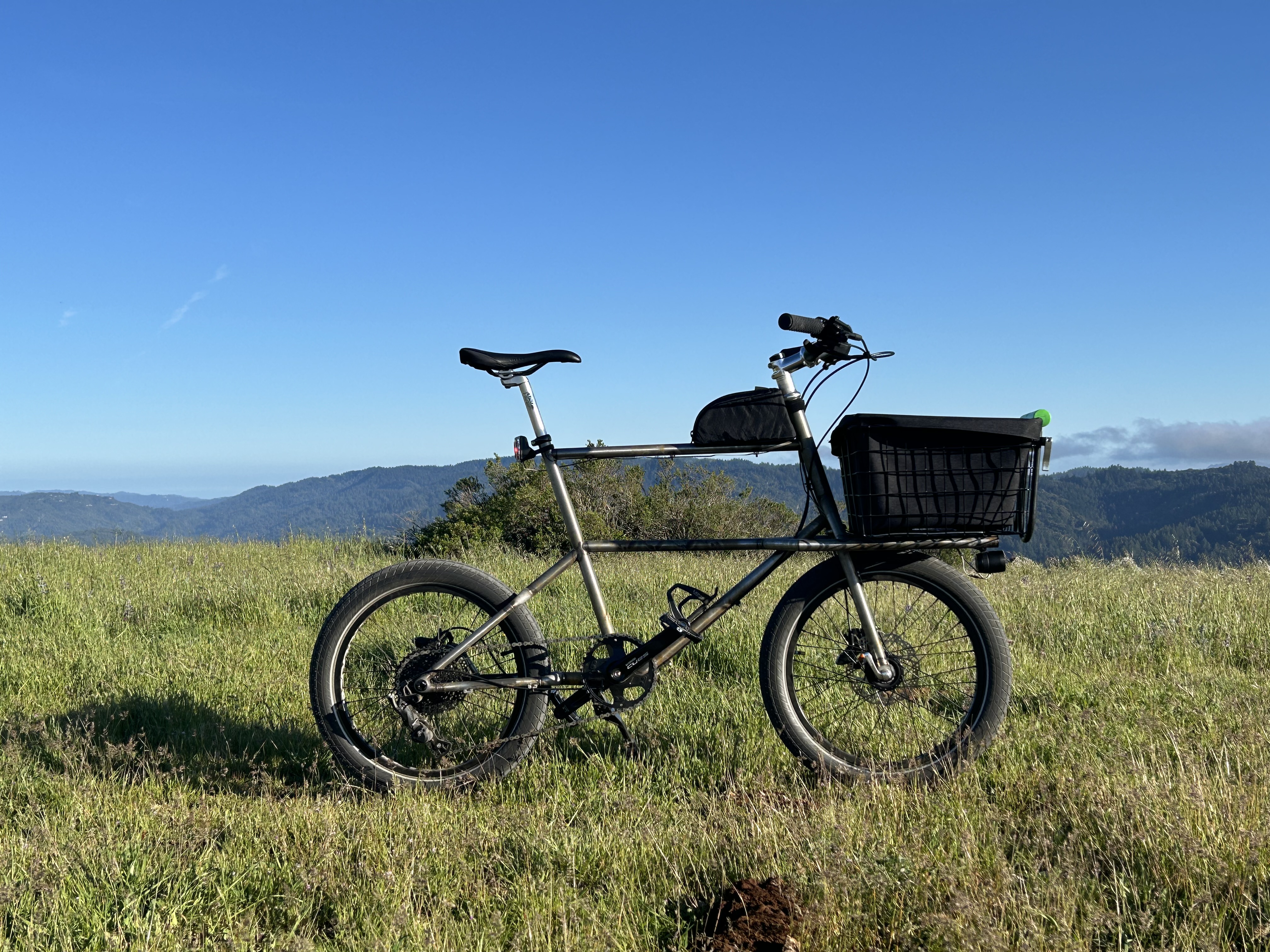
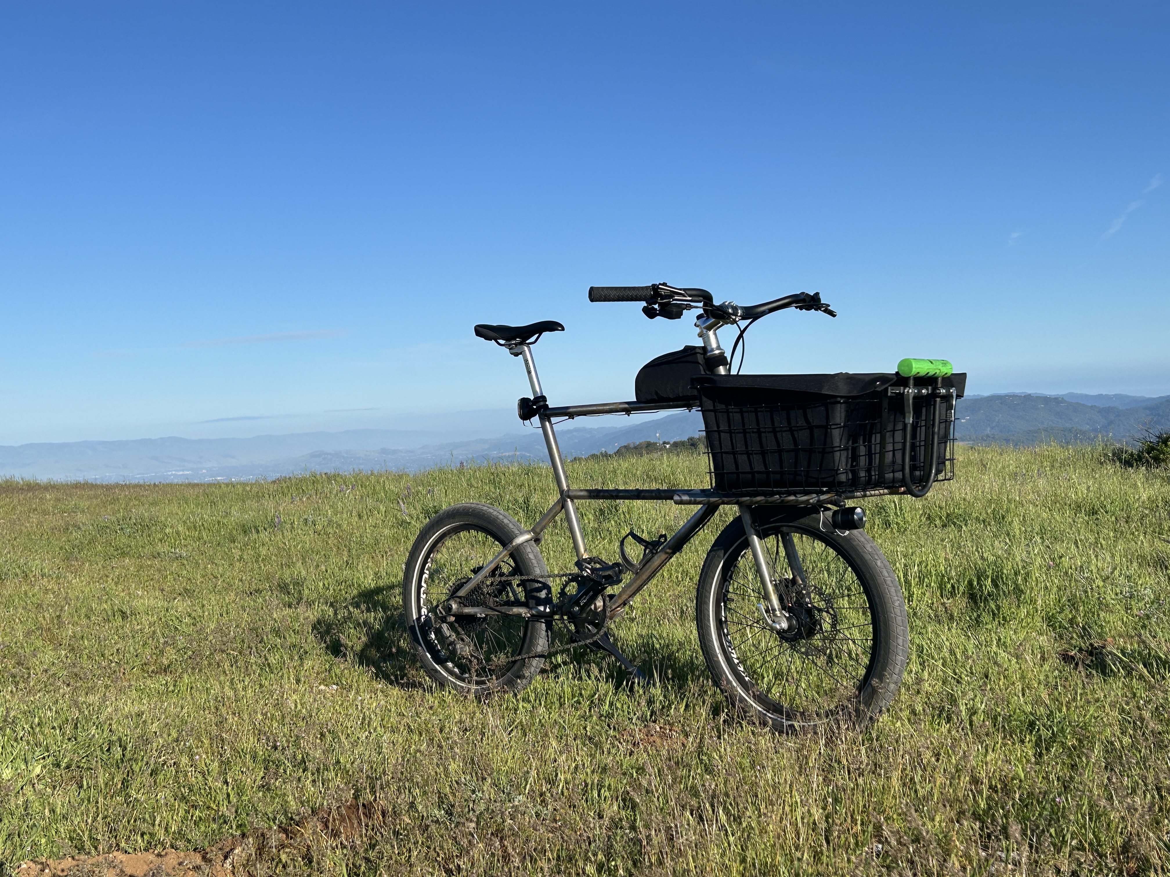
New(ish) bike day! I built a cargo mini-velo to test out 3D-printed stainless parts and laser-mitered tubing from Precision Tube Laser.
I don’t have a lot of seat time on mini-velos but am really happy with how the bike feels. I referred to the Velo Orange Neutrino for geometry guidance. The bike feels responsive yet stable at higher speeds, and I prefer the ride feel over my various linkage-driven cargo bikes.
Design:
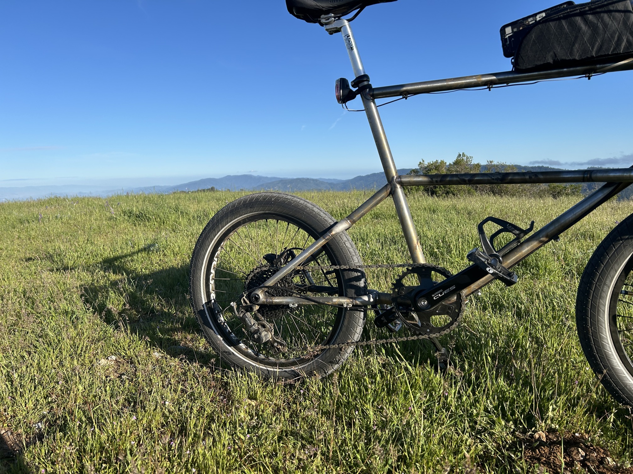
I designed the frame so the downtube and seat stays were parallel, with a horizontal top tube, cargo rack / mid-tube, and chain stays.
Creating the dropouts were really fun - this was a great opportunity to learn surface modeling. I spent a lot of time figuring out a methodological approach to creating guide rails, splines, and G1/G2 surface continuity. I’d love to talk about this stuff more if people are interested!
The front basket is a Wald 157 bolted directly to the cargo rack with a 3D printed quick release U-lock holder bolted on the front and Dynamo light hung underneath. This is my first time using Dynamo lighting and I love it!
Fabrication
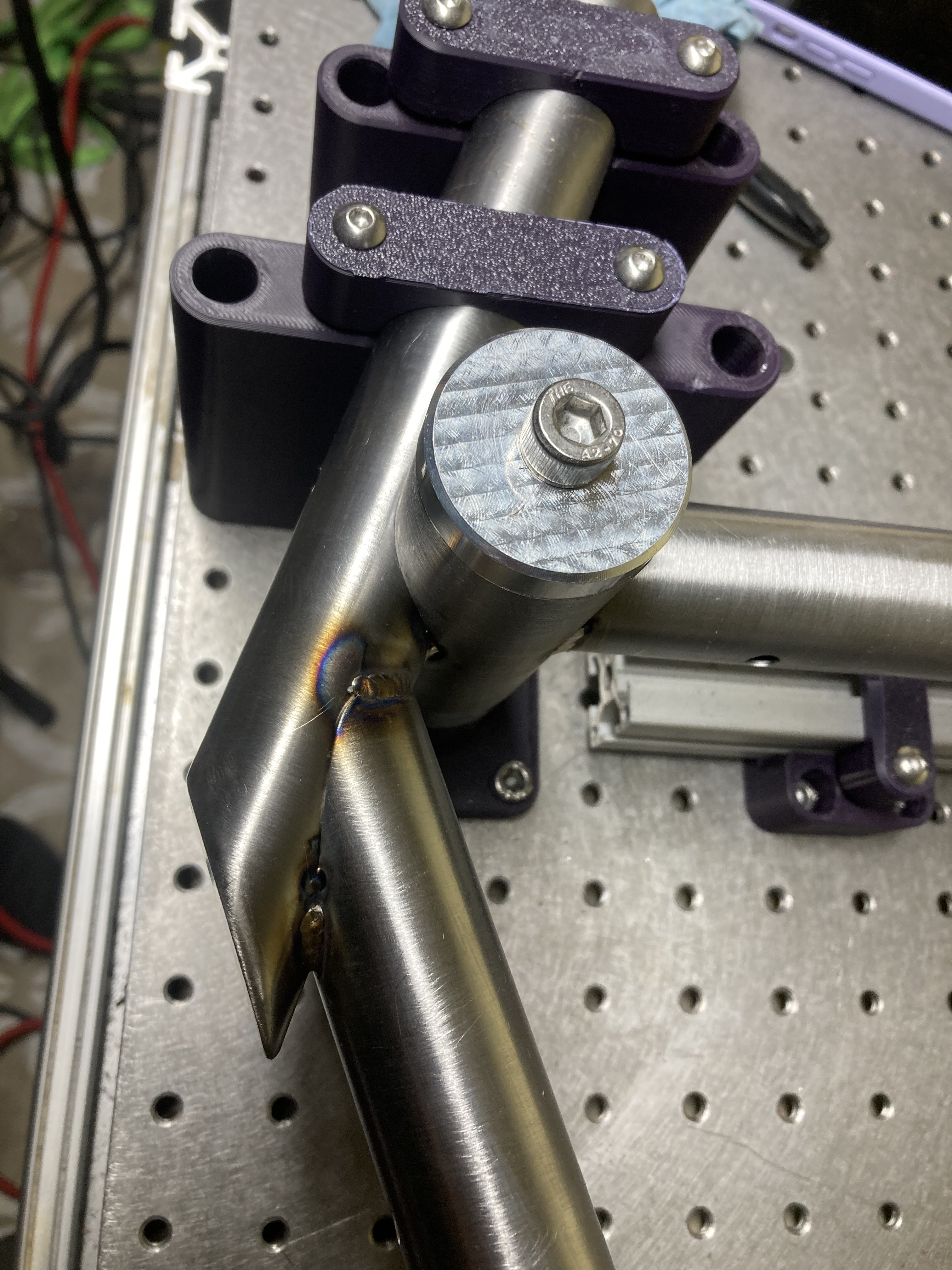
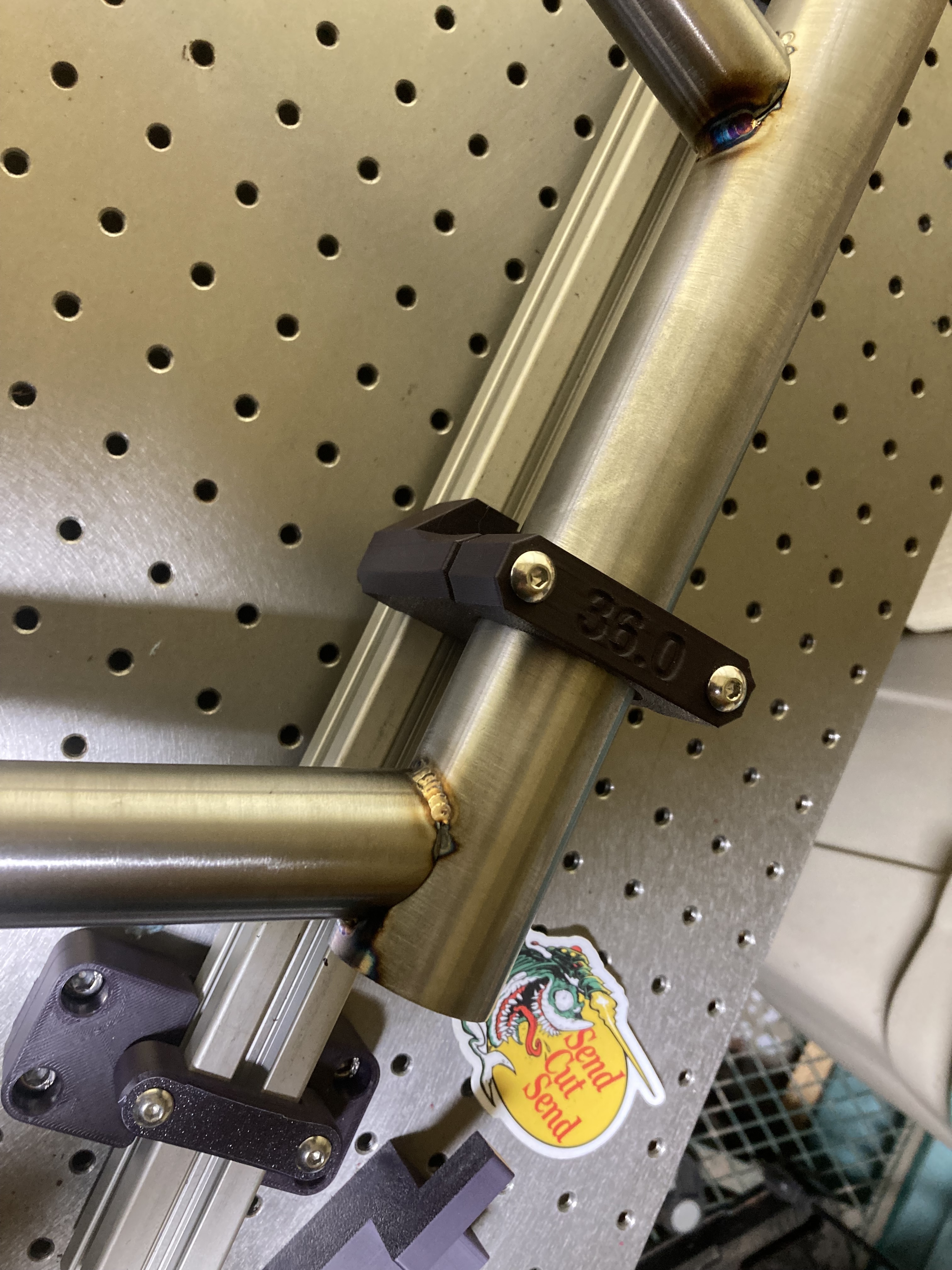
I got all of my 3D printed parts from JLCPCB (SUS316L) and drop-shipped 4130 tubing from Wick’s and Aircraft Spruce to Precision Tube Laser for laser mitering. I was amazed by the speed, customer service, and quality of the laser-mitered tubing. PTL’s customer service / engineering team is amazing and my tubes were cut and shipped within 2 days of arriving at the PTL workshop. For reference - I paid a $45 up-front cost and then $2-4 per tube depending on the complexity of the miter.
I used an optical table + 3D printed brackets (mostly PA-6 CF) and extrusion to fixture my frame / fork. The combination of metal 3D printed parts and laser-mitered tubes resulted in a tight fitup at each joint and made for an easy fabrication experience.
Conclusion
Thank you for looking! I am excited to use tube laser cutting and metal 3D printing (and also high-quality, plastic SLS/MJF prints) in future projects. I’m currently at an internship that ends in June and am excited to take on more projects this summer.
18 Likes
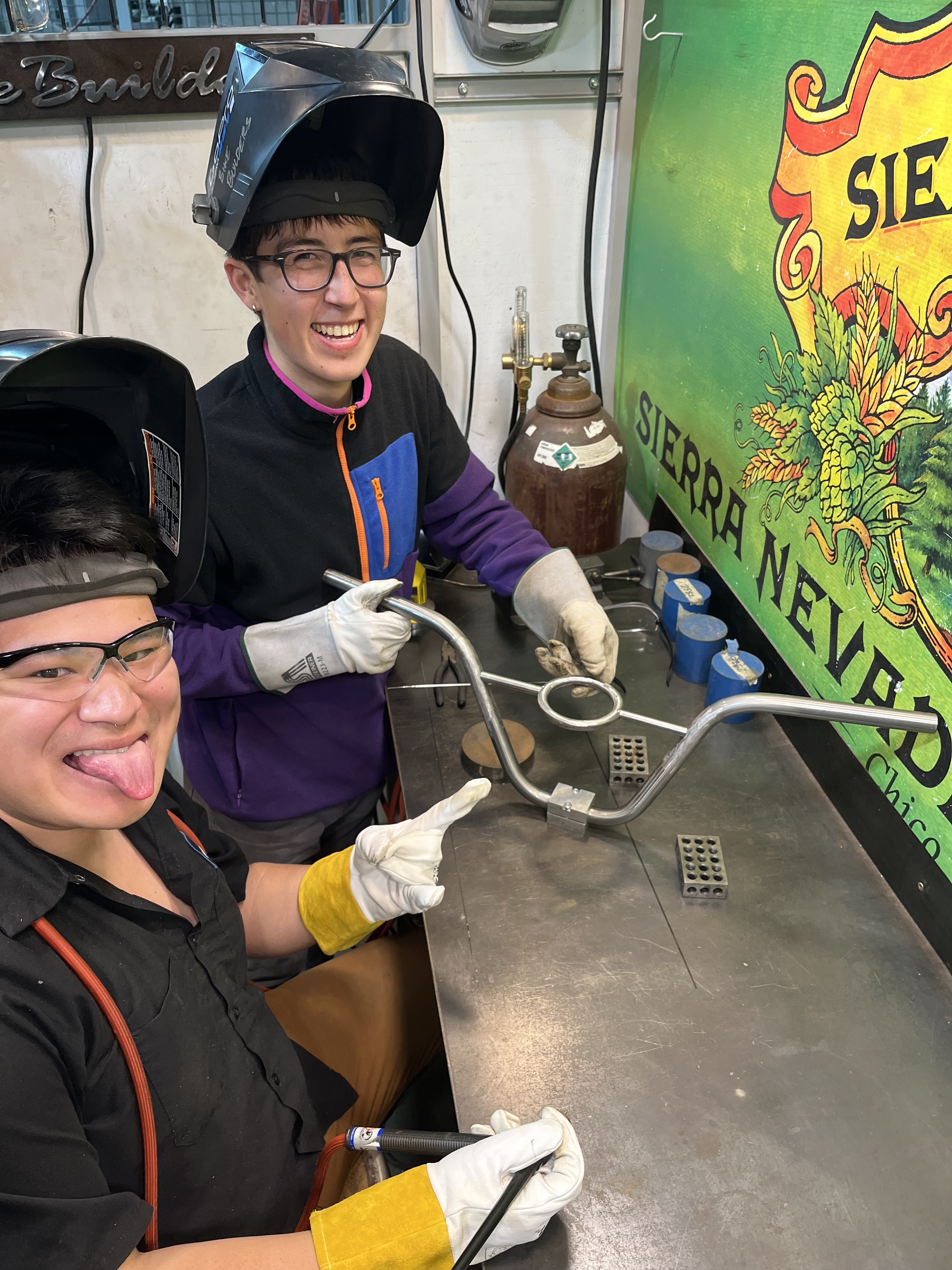
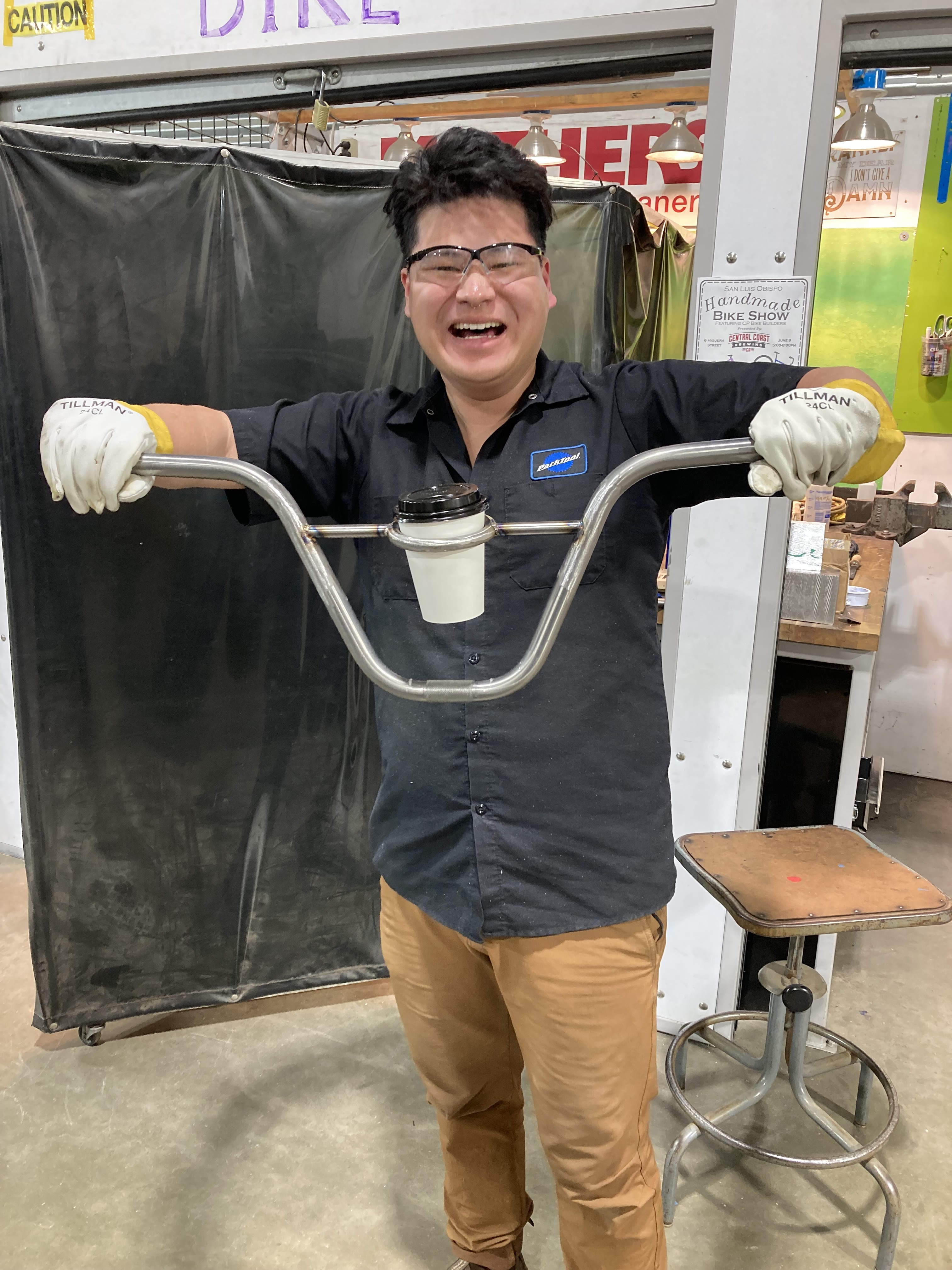
Some smaller side projects / tangents.
My friend Kevin and I made “bevy bars” by welding ornamental steel rings onto BMX handlebars.
Powder-coated tandem.
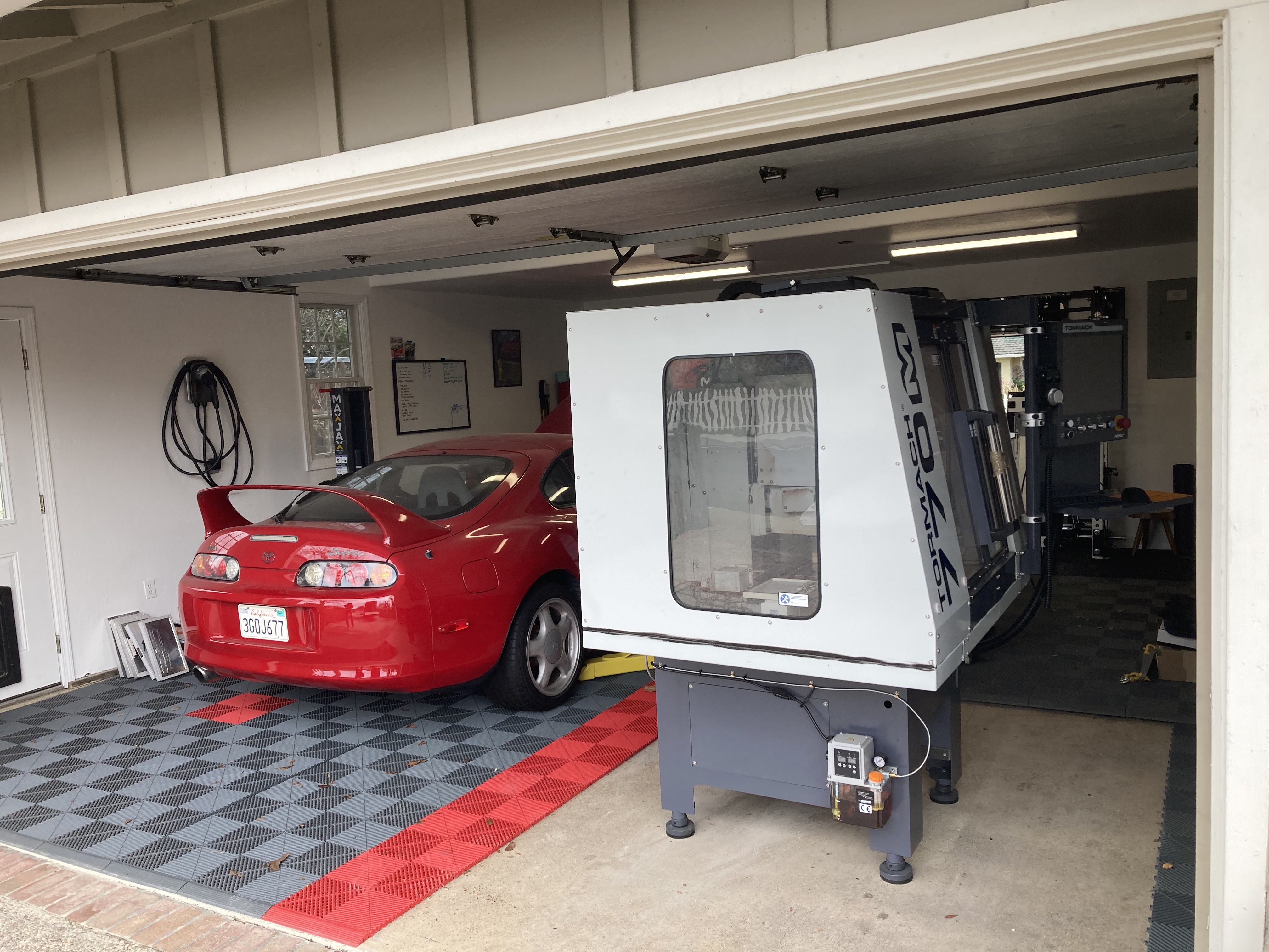
My manager and I bought a Tormach 770M for an amazing price. It’s currently sitting in his shed and I am excited to start making stuff!
11 Likes
Very cool! I noticed oshcut started offering tube laser service but I didn’t know about PTL which seems like a better option. That’s really great it worked out. Did you weld the 3DP parts to the 4130 with weldmold filler?
Also: very rad supra
1 Like