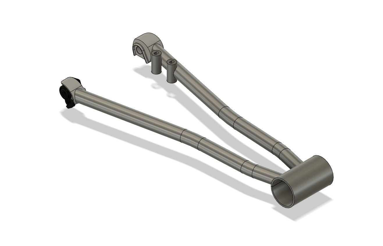
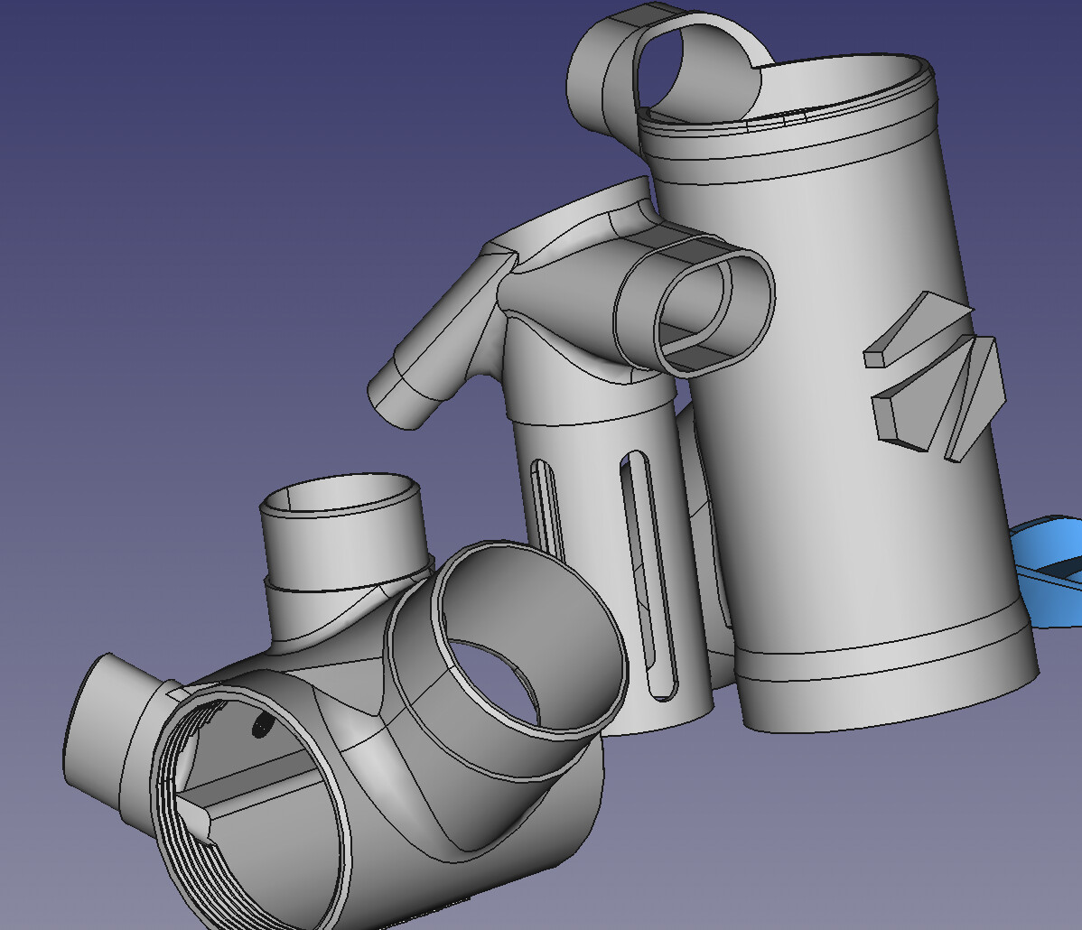
The chainstay sub assembly is the most important part of your custom frame design. It requires the most engineering to handle your drivetrain clearances, tire clearances, dropouts, brake standards, and bottom brackets. A well-engineered sub-assembly can be re-used for many different geometries and bike designs.
Step 1: Clearances
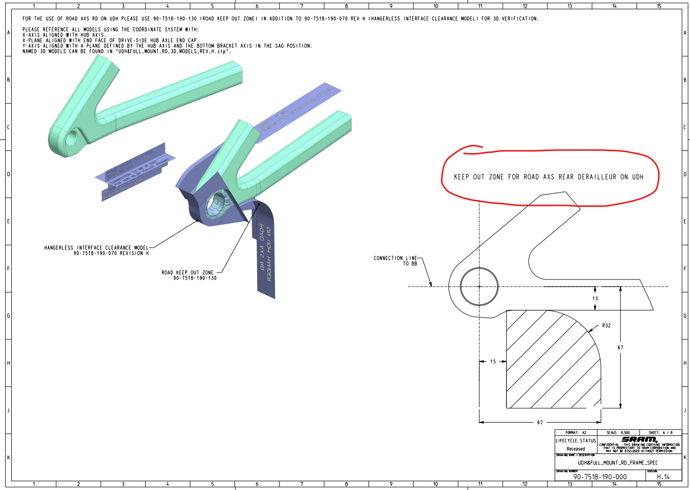
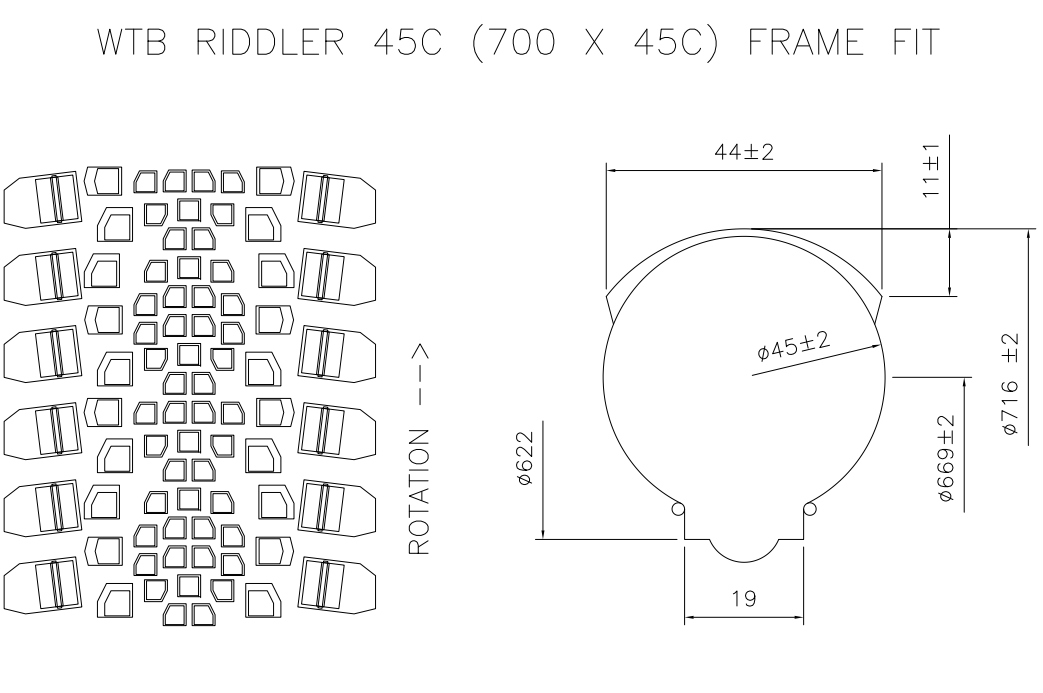
The clearance sketch is your base sketch. It is used to represent:
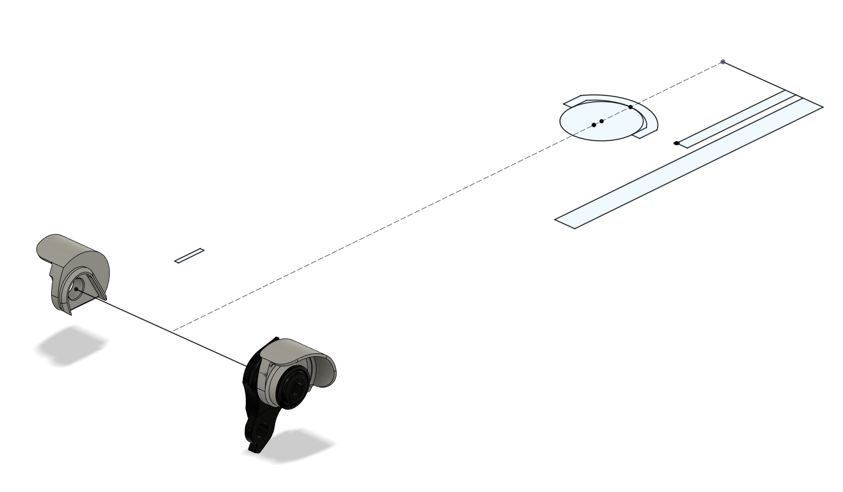
Step 2: Dropouts
Join the dropouts to the clearance sketch. This allows you to visualize where the chainstay will land on the dropouts.
The dropout are clocked correctly if they flat is parallel with the virtual chainstay:
Step 3: BBDR Sketch (Bottom Bracket Dropout Sketch)
The BBDR sketch serves three purposes:
- locates the dropout hood
- draws the bottom bracket
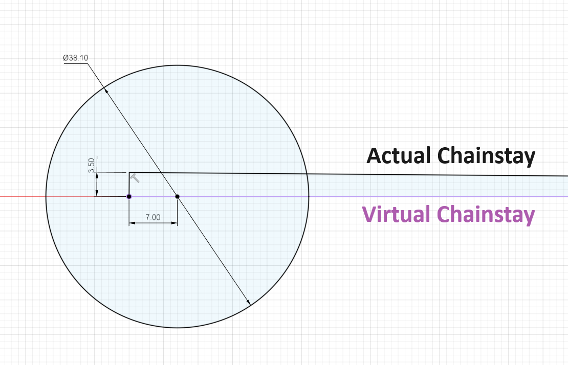
- creates the “Actual Chainstay Plane”
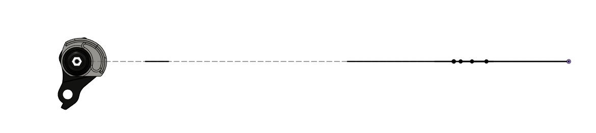
Virtual Chainstay: the plane that intersects your axle center and BB center
Actual Chainstay: the plane that your physical chainstays are drawn on
Note: in order to make UDH dropouts fully compliant, you need to offset the chainstay 3.5mm up
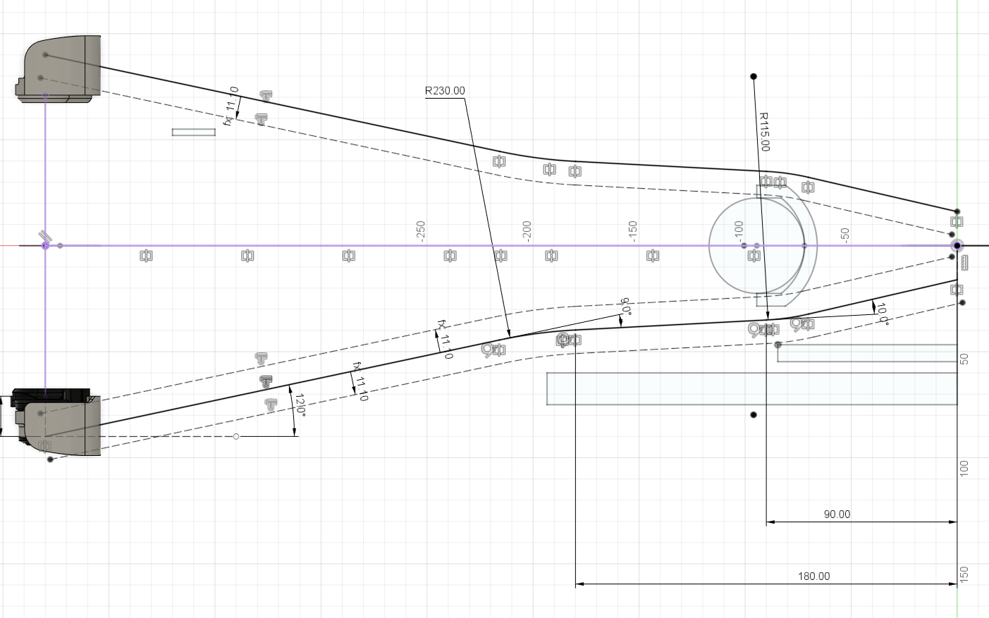
Step 4: Chainstay Centerlines
The purpose of this step is to draw the chainstay inorder to connect the dropouts to the bottom bracket while navigating the crank, tire, and chainring clearances. It takes a bit of art and experience to layout the chainstays. Here is the final solution:
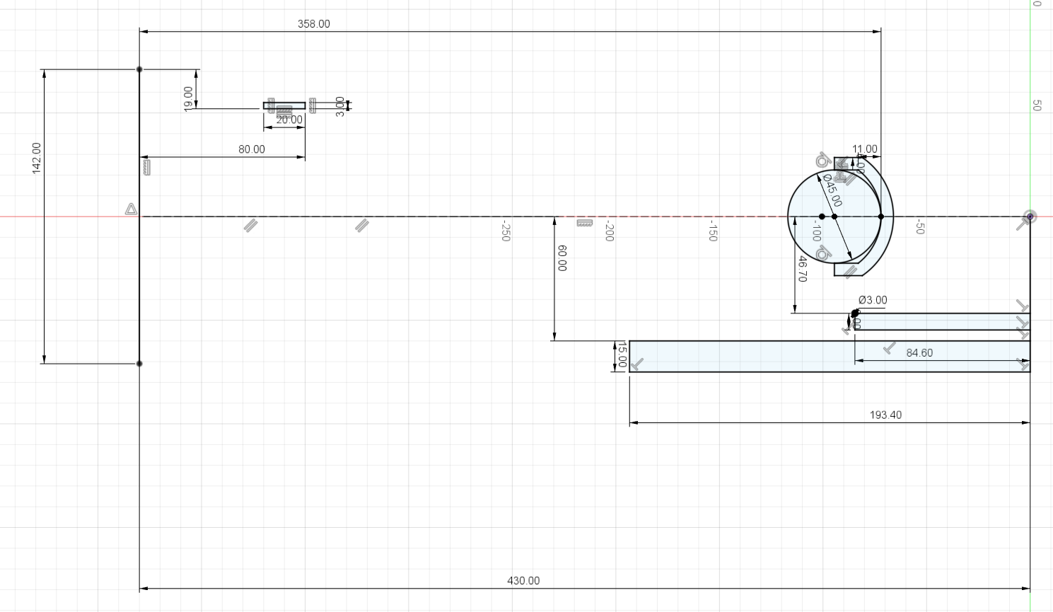
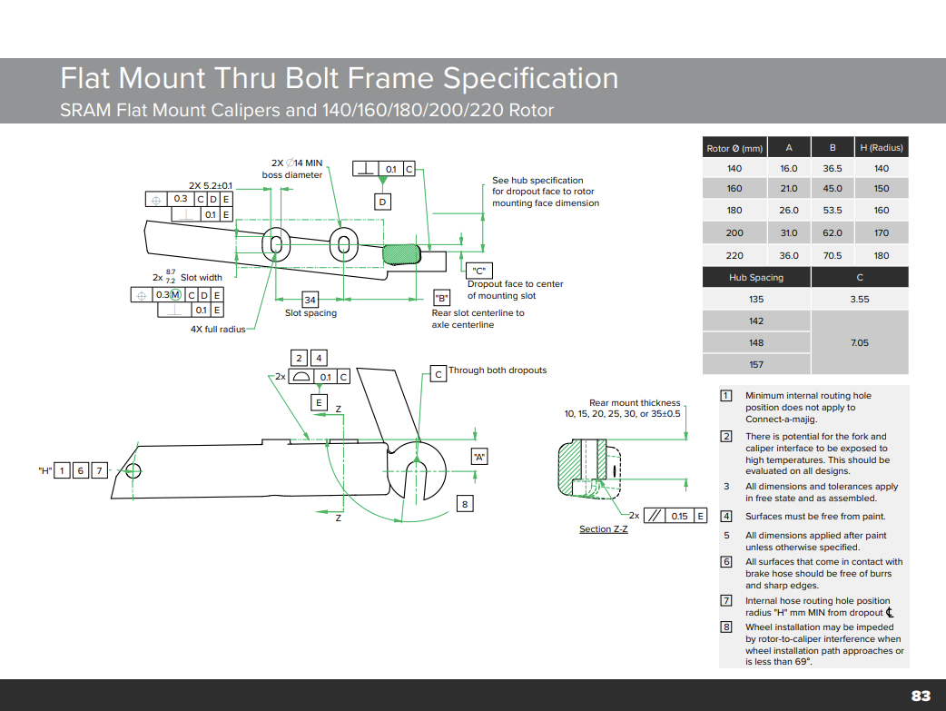
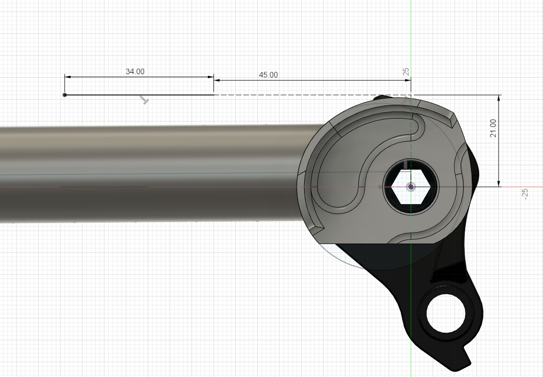
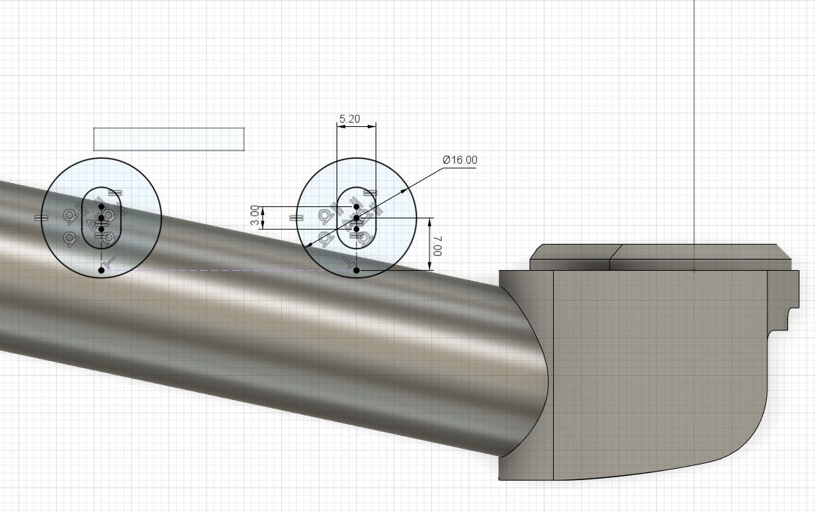
Step 5: Flatmount
DO NOT overlook this step. The flat-mount bosses are the least interesting, but they are the hardest part of the chainstay subassembly to get right. You need to figure out how to do it in CAD before you tackle them in real life.
From page 82 of the SRAM frame fit specifications:
First sketch locates the bosses:
Second sketch draws the bosses:
References:
Drivetrain Clearances: [Standards] Road and Gravel Drivetrains - Cranks and BB's
Flatmount Standards (page 82): SRAMid
Tire Body:
5 Likes
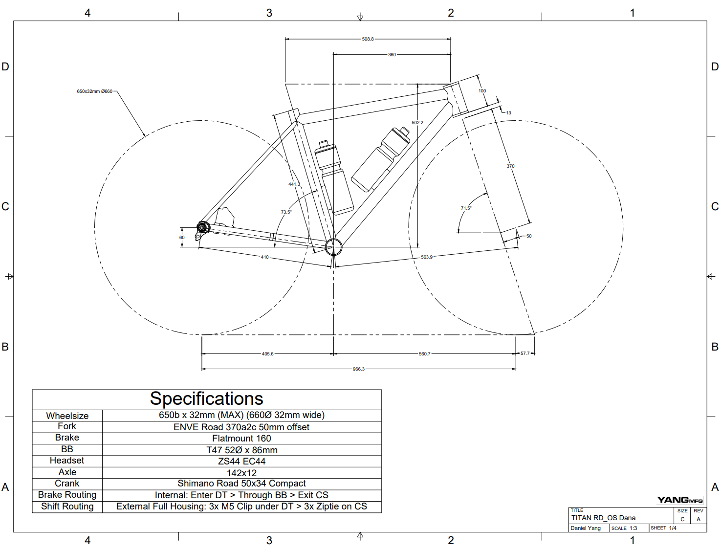
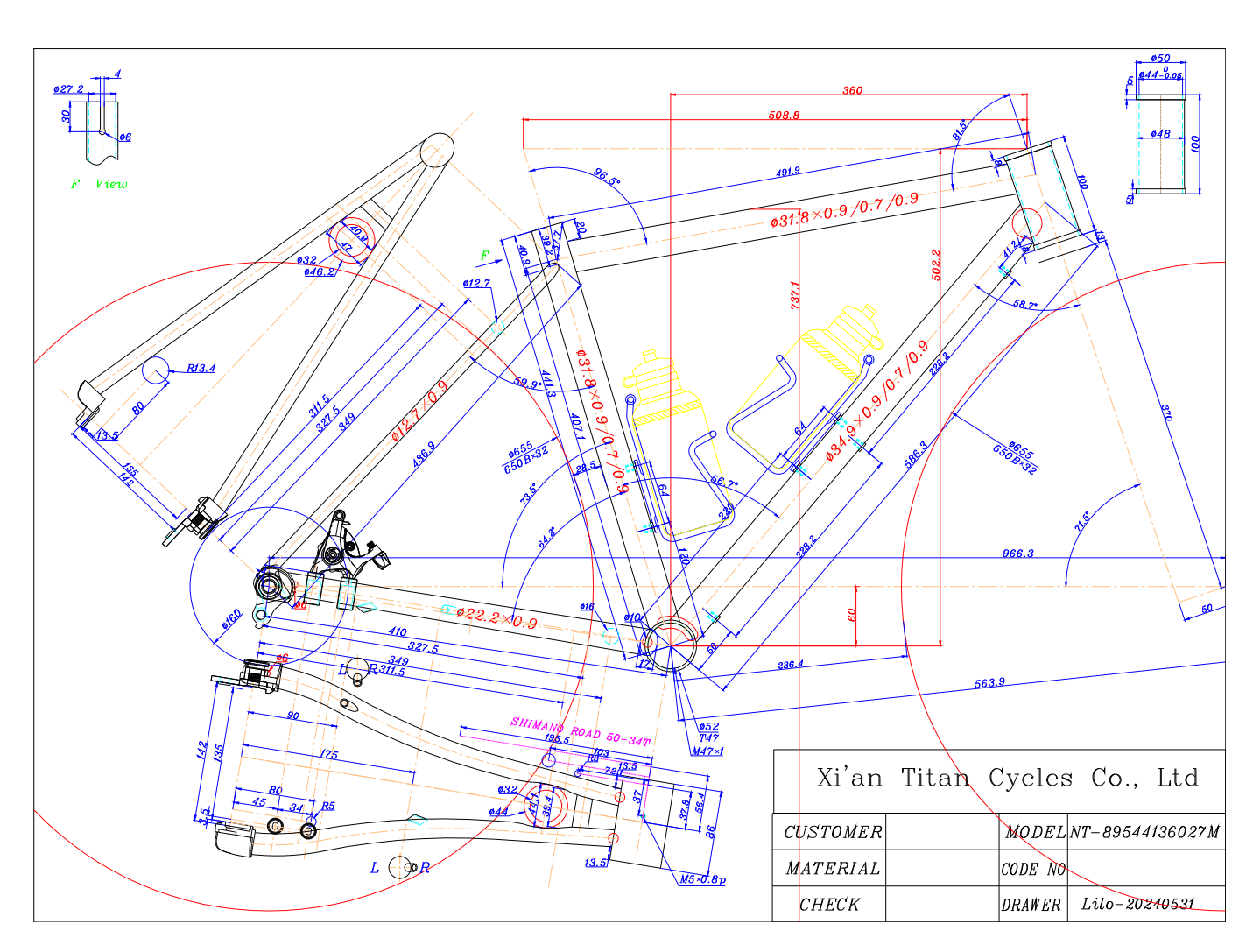
Here is a quick teaser for my next big video project: developing an open source CAD model and sending it to a contract manufacturer (Titan Cycles) to build a custom titanium frame.
A small spoiler: I already designed the frame and sent the drawings to Titan. I have been using them for custom CNC titanium parts (like the UDH dropouts) and tubing. However, I wanted to do a video project to test the capabilities of digital design and open up custom frame designs to more people. I still need to create the entire video and shoot the real world footage!
TITAN RD_OS Dana Drawing v8.pdf (252.7 KB)
This chainstay subassembly tutorial lays the groundwork for that project. If you can design this chainstay, you can design a full 3D bike!
4 Likes
Watched the video, lots of great things learned.
One question. Why do it as it’s own sub-assemply then drop it into you main model? You miss out on parametric adjustments on your base geo sketch it changes to C’s and BB drop are made.
1 Like
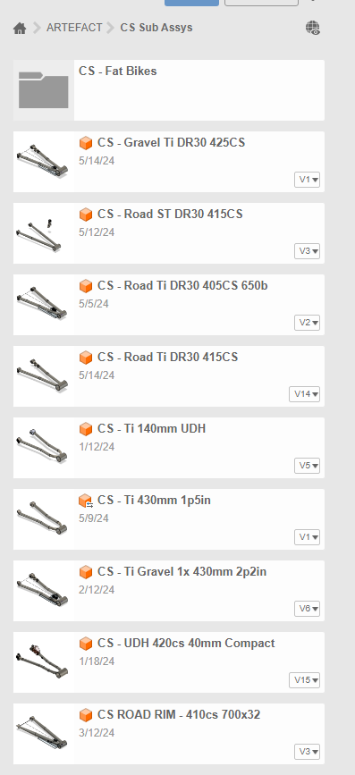
Good question. I used to draw everything from scratch in a single assembly, but now I keep the CS sub-assembly separate because I reuse a chainstay sub-assembly across many models.
I have a library of CS sub-assemblies that I drop into whatever bike I am designing:
The benefit of doing it this way is:
- I don’t have to re-draw the assembly every time (cuts down on mistakes)
- I make a rolling change to an engineered chainstay, and it updates across all my models
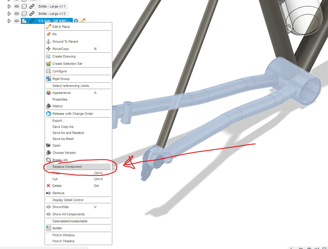
There is also a small hack you can do if two chainstays are very similar (for example, you made a copy and shortened the chainstay length or changed the dropout)
If the replacement chainstay is drawn the same way, it can be replaced directly without any issues, and the drawing will not break. This hack makes it faster to draw bikes.
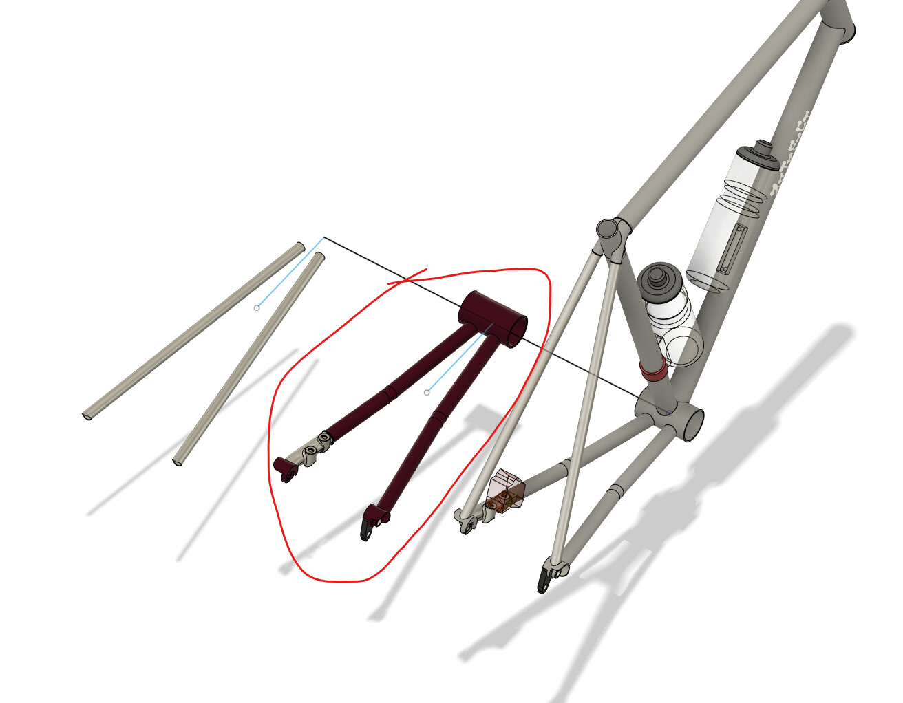
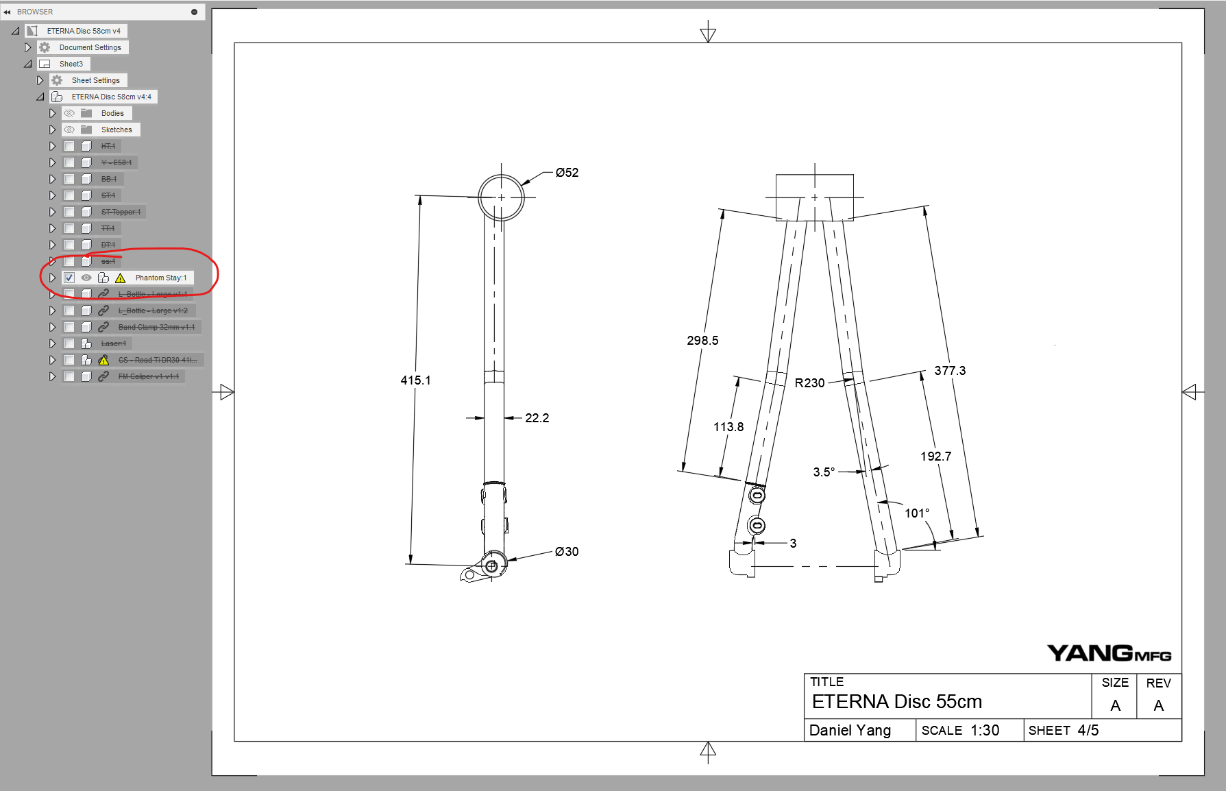
The last reason is particular to my workflow… I create “phantom stays” that are joined to the top plane that I use to reference my 2D drawings to:
2 Likes
can f360/solidworks run on 300$ laptops? have seen every builder use f360/solidworks and it’s seems very powerful and damn pricey—intimidating for me who use opensrouce CAD software 
I’ll try out FreeCAD and see if designing a bike in it is possible.
F360 is free for personal use, but it has limitations. You can always download F360 to see if it works on your computer.
Surely will get the F360 trial. I’m holding to purchase them because just upgrading my macbook
Actually it’s possible. My workaround is design 1:1 scale frames with exact tubing spec then cut them to pieces like this (I plan to make SS cluster for road bikes—it takes 2 months for me lol). Just the cost of it is very high in terms of time and learning curve. Plus they tend to crash while dealing with multiple cross section and fillet joining 
Please let me know if you have something interesting in FreeCAD 
You can download a free student/educator version of Fusion 360…if you’re affiliated with an institution. Should be able to via an institution email address.
Will you post the fusion file for the open source drop out?