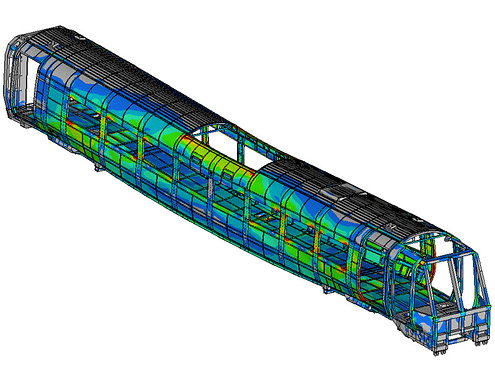
So, the topic of “FEA” or “simulation” for strength and stiffness in framebuilding comes up every once in a while, and since it is a very useful tool and the accessibility to it inside a lot of CAD modelling packages is getting better and better, more people can start using it. Which is generally a good thing to begin with!
Like everything in natural sciences, there are a few strengths and weaknesses associated with the method, and there are cases where it can give very reliable answers but it can also be misleading when used incorrectly.
I thought it might be useful to have a thread on here to explain very generally how it works and how it can be a useful tool, and also where the results coming from it have to be taken with a grain of salt.
I used to work for one of the global suppliers of engineering simulation software as an application engineer for almost a decade, so I feel like this might be an area where I can contribute for the benefit of the community.
Keep in mind though, that this is targeted at the mechanically minded people that you are, but not towards experts in the field of numerical computing, material sciences, mechanical physicists… All the explanations given will be simplified for the sake of comprehensibility and will not stand up to scientific scrutiny. However, should you feel that something I stated is just blatantly wrong, please do speak up!
1. Finite element analysis - the basic principle
So, the basic idea behind FEA goes something like this: We can analytically calculate the deflections and the resulting stresses within objects that have a very simple shape, like a tube or a brick or a box section, when they are loaded in a very simple way. However, this gets increasingly complicated or even impossible with arbitrary shapes and loading scenarios. So the idea is to break up whatever object you want to analyse into “finite elements”, little bits that resemble an easy enough geometrical shape which can then be calculated.
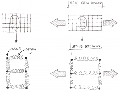
In a very crude simplification, one can imagine it a bit like this:
These would be so called “quad” elements, they’re made up of four nodes in the corners and something like a spring of a certain stiffness connecting them together. Since we know the stiffness of the spring from the material’s young’s modulus, and we generally know how a rectangle behaves under a certain load, we can calculate the movement of each node . Therefore we know by how much each individual rectangle will change its shape and how the force is passed on to the neighbouring elements.
We can calculate now, how much and which way every single node will move and hence how each element will be deformed under load. This would be called “strain” and it can then be translated into stress.
There’s one important thing to take away from this: In an analytical result, I get all the stress values and all the displacements for all the possible spots within my component. In an FEA, I get displacement results only at the nodes and a stress representation within each element. That’s the “finite” in FEA. I only get a finite amount of data points. Everything between these points is an interpolation of the values.
With this info in mind and the fact that the behaviour of a component is heavily influenced by its shape, it becomes clear that the shape needs a representation of some accuracy in order to produce meaningful results. Given the fact that the element edges between the nodes have to be straight, approximating a circular shape may look something like this:
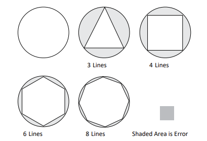
The more nodes (and therefore elements) I use, the more accurately the shape is represented by the elements. If taken to the extreme, this can have quite dramatic effects on the results we are getting from a simulation.
Another important thing to know with respect to accuracy is that the computation of all this data works most accurately when the elements are as close to their “regular” shape as possible. A good triangular element would have close to equal sides and a four-sided element would have as close to all right angles as possible. This isn’t always possible, but generally the method works best when the elements are “of good quality”
2. Different element types and their influence on results
(skip this paragraph if you don’t want to be bothered with too much theoretical nerdy stuff and go straight to the conclusions)
Generally, there are three groups of finite elements for modelling most of the stuff we want to analyse.:
a) 1D-Elements
These are used for long, slender structures that have a continuous cross section, like I-beams, box sections or also structural tubing. In the model, these elements are represented by a line connecting two nodes. Inside the element description, there is more information about the cross section so the stiffness of the beam is defined. Usually, 1D structures are only used to represent the stiffness of a structure. Due to the nature of these elements, it is impossible to determine where exactly within a cross section the stresses are located. Or, for that matter, if the stress on the downside of a DT/HT junction is too much ![]()
In our specific context, they can be used for example to represent a fork or a crank arm in a frame model that we just use to constrain or feed load into the frame itself.
b) 2D-Elements
These are used for structures where one dimension is a few orders of magnitude smaller than the two others, such as sheet metal, tubes, welded and folded components, injection molded products… The location of the nodes already carries a lot of information about the geometry of the component, only the wall thickness of the area represented is defined within the element description.
These elements can be used for all sorts of analyses. If used correctly, there is no limitation in accuracy. The benefit of using 2D elements is that you can get away with using a lot less elements compared to modelling in 3D, which saves you computation time. The downside is that the modelling itself is more labour intensive as you have to extract the mid-surface of all your sheets, something that unfortunately isn’t supported in most CAD systems. There are automated midsurf tools but there is still a lot of manual cleanup necessary.
A lot of state-of-the-art sheet metal simulation including weld beads, spot welds or surface adhesives is based on 2D elements, there is a lot of well documented literature on it and it is very well researched.
c) 3D-Elements
Now that leaves us with the most versatile of all, the 3D elements. They can literally be used to model whatever a shape might look like.
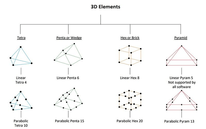
There is one significant difference to the 1 and 2D elements: The shape of the object is now solely represented by the location of the nodes of these elements, and the stiffness and stress results are directly dependent on the shape of the elements themselves. This will become important a bit further down, but first I have to quickly introduce two different 3D elements: the Tetrahedron and the Hexagon (forget about penta and pyra for now as they are not relevant in this context)
There are two main differences between hexas and tetras:
Tetra elements can be generated automatically within any solid object using a bunch of different methods. Hexas however have to follow very regular patterns and to my knowledge there is no automated algorithm that can produce a good hexa mesh in a random solid. Manual hex meshing is very tedious and complicated for any shape that doesn’t resemble a brick. Tetras unfortunately are known for artificially increasing the stiffness of the loaded structures, especially if there aren’t enough of them or they are skewed and warped/of bad quality.
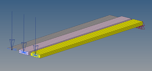
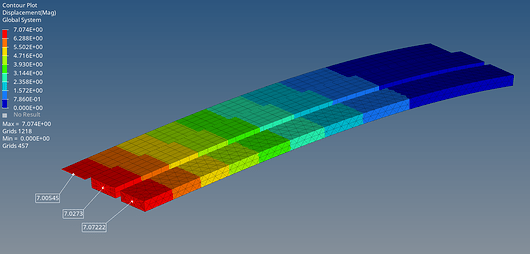
To illustrate this, I have built the same steel beam with 2D quad elements, two layers of hexas and two layers of tetra elements.
The beam is constrained at one end and pulled down on the other end.
First, let’s look at the stiffness or the displacement as we like to call it in simulation. As we can see, the beam modelled with 2D elements shows the largest displacement, followed closely by the 3D hex. The tetra element beam flexes the least, almost 40% less than the 2D quad beam.
The “true analytical result” for this is a displacement of 6,89mm by the way.
This behaviour can be mitigated by so called “2nd order” or “parabolic” elements (see picture above) that introduce additional nodes on the edges of the 3D elements, so the results of all three variants are almost identical and quite close to the analytical value:
In some CAD embedded simulation tools, the option to use 1st or 2nd order elements is available through a toggle switch somewhere in the preferences, sometimes labelled “faster/more accurate” or similar. Of course, using 2nd order elements comes at the expense of more computation time. More data points - more equations to solve…
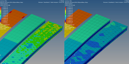
Now, let’s look at the stresses in this beam in both 2nd and 1st order meshing:
We can see that the stress result of the 2D elements is clearly the highest, and also pretty close to the analytical value of ~207MPa. Both the hexa and tetra, 1st and 2nd order meshes are showing a lot less (2nd order on the left). Note that these results are already adjusted across the volume of the individual elements to reflect the fact that there is almost no stress in the centerline and the max on the top/bottom faces. The stress displayed on the 2D shell elements is the theoretical max value on the surface of the profile and is calculated from the in-plane bending of the element and its assigned thickness.
So, remember what I was saying about how strain and stress values are calculated: Essentially, you have one strain value per element, from which stress is derived. If we want to increase the accuracy of these results with 3D elements, we will have to use more of them across the thickness of the component. At least 3 layers is considered good practice here. And because we would like to use elements of “good quality”(~equal internal angles), we would have to use a finer meshing across the surface area as well.
Now, in frame building, we are dealing with very thin wall thicknesses. In a frame with ~1mm wall, this would lead to a model with millions of elements. It would keep even the fastest multicore CPU and all the memory occupied for a while, so the feasibility of this approach is questionable.
Of course, in professional FEA software there are tools and strategies to avoid this situation, like local mesh refinement or submodeling. But most of us do not have these tools at their disposal. CAD embedded FE modeling tools usually exclusively work with tetra elements since they are easy to generate automatically, and most of these tools don’t even let you see the mesh they generated, so it can be hard to see what you are doing.
3. What does all that mean in the context of framebuilding?
Let’s assume we have some sort of finite element representation of our frame or a part of it, now we need to turn that into a model by adding constraints and loads, and organising them into load cases. I don’t want to go into detail too much here because there are a gazillion ways to do this and nothing is definitely right or wrong. Best practice would be to try and come up with some sort of reasoning why you chose to model it the way you did. How did you come up with the amount of load, the direction of it and how do the different loads act together in a loadcase? Why did you constrain the model the way you did? In doing this, you might have an idea of how the structure should deform under load. Now, when you run the simulation, this would be the first thing to check. Does it bend the way you expected it to? If the answer is no, maybe one or more of the constraints isn’t doing what you wanted it to. Usually, when defining constraints, the default is to restrict any translation and rotation in any direction on the selected surface. This might not be what you wanted, so be careful what you do!
Now that we have a general Idea about how the whole shebang works, we can see that some questions can be answered pretty easily while others might be very hard to answer with sufficient certainty. Here is my little list of answers in ascending order of effort needed
- Which one of the different versions of my frame is the stiffest?
If the modelling technique used in the versions is consistently the same (same element type, same constraints etc.), the actual stiffness value might be incorrect but the relative differences should be pretty accurate most of the times
- Which of the different versions of my frame is the stronger one?
One step more difficult from the previous question, in this case the constraints need to be pretty realistic and the loads need to be pointing in the right direction. Otherwise the stresses would be in different places than they are in reality. The meshing doesn’t have too much influence as long as it somehow reflects the shape of the frame. The actual value of the stress might be incorrect but again, an A/B comparison should be possible
- Where are the stress hot spots in my frame design?
Almost the same difficulty level as before, with the added task of just having a fine enough mesh in the areas that are interesting to get a good enough “resolution” to see what’s going on.
- How stiff is my frame in a certain scenario (like pedalling for example)?
This is fundamentally harder to get right, since both direction and magnitude of the loads and the constraints must be correct. The meshing must be of a quality that gets the displacement in the ballpark. The quality of the meshing doesn’t have to be super good since the areas with the most displacement are usually not the ones with the highest stresses and a few warped and skewed elements in an otherwise OK mesh produce halfway reliable displacement values.
Up until this point, all the questions can be answered with sufficient accuracy, without using highly specialised FEA software and without spending weeks on modelling. From here on, this changes…
- How high are the stresses in my frame under various defined load cases?
All the factors of the points before have to be met, plus the meshing/selection of element types in various areas and connecting them together has to be spot on. Industry standard to achieve this is to do various example models with different meshing methods and qualities, with increasing mesh density until the results don’t change any more. Ideally, this is backed up with a lab test result of at least one load case.
- Is my frame going to break?
I quit ![]()
In all seriousness, this is almost impossible to answer with a simulation alone. So much so that even the bike industry doesn’t do that. The reason is that you will never get all the loads and use cases right, and you’ll have a hard time capturing all the material properties for the fatigue behaviour. There are also residual stresses from manufacturing processes to consider, as well as heat treatments or the lack thereof…
What the bike industry mostly does in simulation is replicating the testing machines in FEA. The tests a production frame has to go through are statistically relevant enough that they can say with enough confidence: If our frame survives the testing machine, it most probably will survive most of what our customers will do to it. And then we use simulation so we don’t fail on the actual testing machines too often.
Ok, I hope a few of you made it through to the end without falling asleep!
I’d be happy to answer any of your questions to my best ability, or discuss anything simulation related in this forum topic!
