Flexing your Stays?

hey all,

I see a lot of metal bikes (steel and ti) using a flexing seat stay rather than adding another pivot point. What are some factors to consider with this design? Does anyone have a good rule of thumb for how far a stay can flex? I’ve drawn up a few flex stay designs and am starting to get serious about building one. I generally try to keep the change in angle (seat stay to chainstay) within one or two degrees. Is this an acceptable range of motion for a smaller diameter, thin walled tube?

1 Like

Do this experiment. Put whatever tube you are considering into your vice and flex it holding the tube at the distance you will have from your drop out to connect at shock. I think you will find you can flex it a fair bit more befire feeling any real resistance in the tube. For example my XC rig goes through about 3 degrees in movement. I can easily flex it to 10 degrees and its only just stsrting to resist the bending force.

3 Likes

1-2° sounds okay. Like Sean says, it should be pretty easy to do some practical tests. Look at how much deflection you need over the length of your assembly and test it out.

Depending on the joining method it might be wise to try and keep the flex away from the joint.

Also think about the brake mount and whether that is affixed to the flexing member.

Let us know how it goes :+1:

1 Like

Thanks for the feedback, that is a great simple experiment to try. I’ll follow up or possibly do a full build thread on this bike, since the community always has such great tips and feedback

4 Likes

I would not be concerned about seat stay flexing. You should be clearly in the elastic part of the stress-strain curve.

My concern is the weld between the SS and dropout. Bend tests can’t show fatigue. That area is the perfect storm: highest stress concentration, weakened steel (heat affected zone), and stress riser.

This is why early steel disc forks cracked at the tip of the brake tab:

The fork undergoes much less flex an full suspension rear end would.

1 Like

would putting a bend in the seatstay cause it to flex more around the bent area?

1 Like

A clever way to control flex is to squish the tube in the desired “pivot” location, see the reeb sst chainstay. The idea is that your flex will be isolated to a non welded zone of your choosing, and the lateral stiffness will remain high.

2 Likes

The first example of Flexstays I remember was Swarf out of the UK. Check out their Contour model for some inspo if you haven’t already.

One really interesting thing I remember reading is they designed their flex stays so they were in zero tension at sag but slightly in tension unsagged.

image

2 Likes

I have built a fs frame that relies on flex for two pivot points.


The frame is 160mm of travel, I think this is one of the longest travel frames to rely on flex and certainly the longest travel to skip two pivots for flex.

The rear end is at zero tension at roughly 40% travel so just past intended sag. With this it’s splitting the total flex distance to a + and - from zero tension. I can easily cycle the rear end through most all of it’s travel with a light finger push (might actually be all it’s travel never actually measured it).

Video of cycling the rear end here.
https://www.pinkbike.com/video/585846/

So far it’s been abused pretty good, raced a few enduros on it and the Psychosis DH including the massive road gap. I was hoping to get some Whistler bike park days on it this year but didn’t pan out.


Only issues I’ve had has been with my cs to drive side yoke, pretty sure this is my crappy brazing skills and not from the flex, I also should have used a thicker gauge tube in the cross braze between CS’s at the yoke.

I plan to develop this further and move to a flex CS to mimic a Horst layout on the next frame.

9 Likes

@earle.b that bike is very cool. Really inspiring me to try flexing members on more bikes as well. What is the chainstay length on that bike? it looks quite long, but thats not always a bad thing

1 Like

The CS are 462 and the WB is 1305. Long boi.

  • Correction after posting the above. I had forgotten the measurements and pulled up the file…turns out it was the wrong file.

CS is 450 and a 1280 WB is what I had built. The above numbers were a full DH version I was playing with the idea of building for Psychosis.

3 Likes

I’m playing around with a design like that as well, will probably start building it at some point this winter.

If all the linkage points stay were they are now (I highly doubt that… :wink: ) the stays will flex about 7mm (±3.5 or +2 -5 or whatever…)
Assuming a 16x1 seatstay, this would lead to a flexural stress between 90 and 150MPa, depending on where exactly the “unstressed state” lies within the range. According to my preliminary “guesstimates” involving Woehler charts and Smith Diagrams, there should be plenty of load cycles in these stays. According to literature, regular 4130/25CrMo4 can indefinitely withstand a flexural stress of 450MPa (chart).
However, I think the devil lies in the details, it is probably a bad idea to just buttweld the stay to the dropout and creating a stress raiser in the most unfavorable spot, so I’m exploring other possibilities…

One thing that has come to mind would be using something like a leaf spring. X10CrNi18-8/ AISI302 is corrosion resistant, can be welded without post heat treatment and when cold rolled into a leaf spring has a tensile strength of something around 1200MPa, so theoretically should be up for the task.
I think I’ll look into this a bit further, can’t really imagine that this spring steel will keep its properties post welding without any heat treatment. Maybe silver brazing would be the better option?

5 Likes

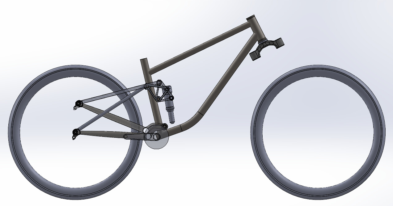
Really interesting thread! I’m planning to “smoosh” my seatstays to create a flex point for a new frame build, similar to what Reeb does on the SST (thanks for showing this, @RxDesigns).
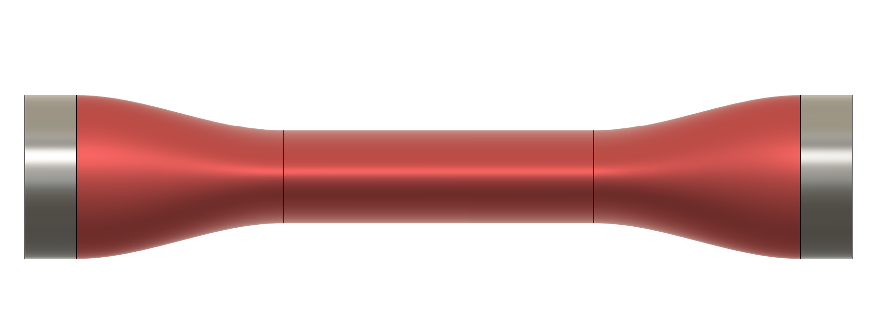
Smooshed Shape

My smooshed seatstay section is 5/8"x.035, 70mm long, with a 20mm transition between round and elliptical cross-sections at either end and 30mm of an elliptical cross-section in the middle.

I followed the approach Daniel describes in his dimpling write-up to use a constant cross-sectional circumference to size the elliptical shape. I wasn’t sure how much spring-back would occur (I’m using normalized tubing from Wick’s Aircraft) and under-sized the ellipse by about 1mm in height to 9mm x 21.4mm.

Modeling: I created circles at both ends of the smooshed section and used these sketches to create cylindrical surfaces. I repeated this for the elliptical shape in the middle. The transition sections are surface lofts between the cylindrical and elliptical surfaces with a tangency (G1) edge condition at both ends.

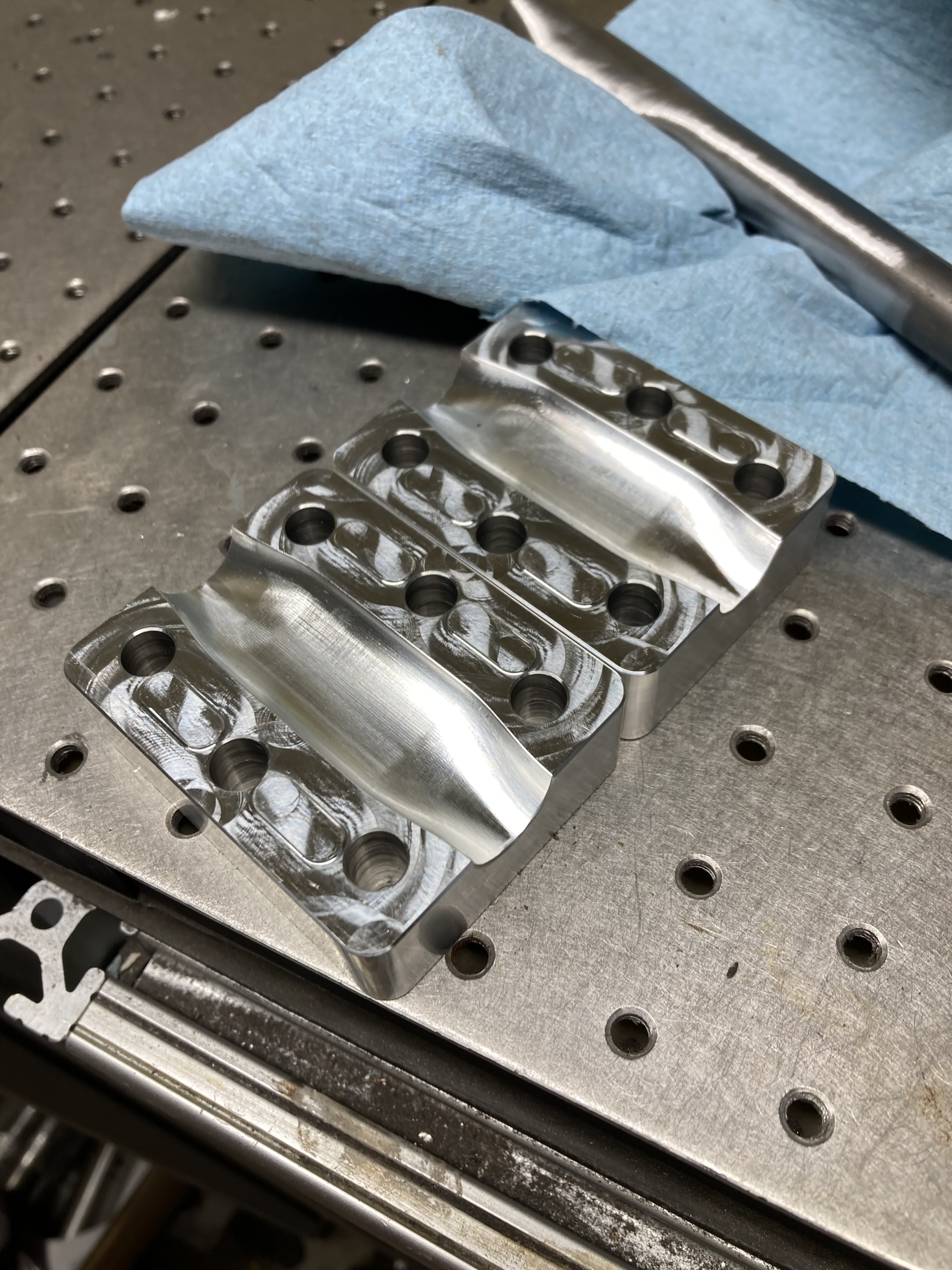
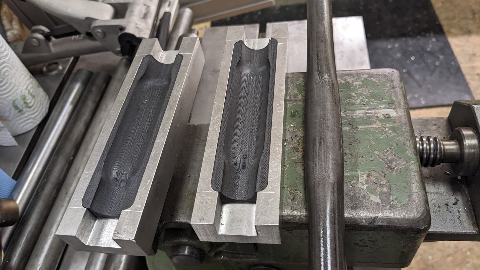
Die: The design for my smoosh die was inspired by Paragon’s tube blocks and a cool youtube video I found on a bolted chainstay press. There is a 1mm air gap between the upper and lower sections with 4, 0.5mm-tall pads that allow the die to bottom out when clamped. I subtracted the smooshed shape for the dies and machined the final design out of 6061.

Results

First, a picture of the die/press. The die has six bolt holes for clamping but my initial tests were done using a vise to press the two halves together (the hardware store wasn’t open in the morning when I tried this, lol).

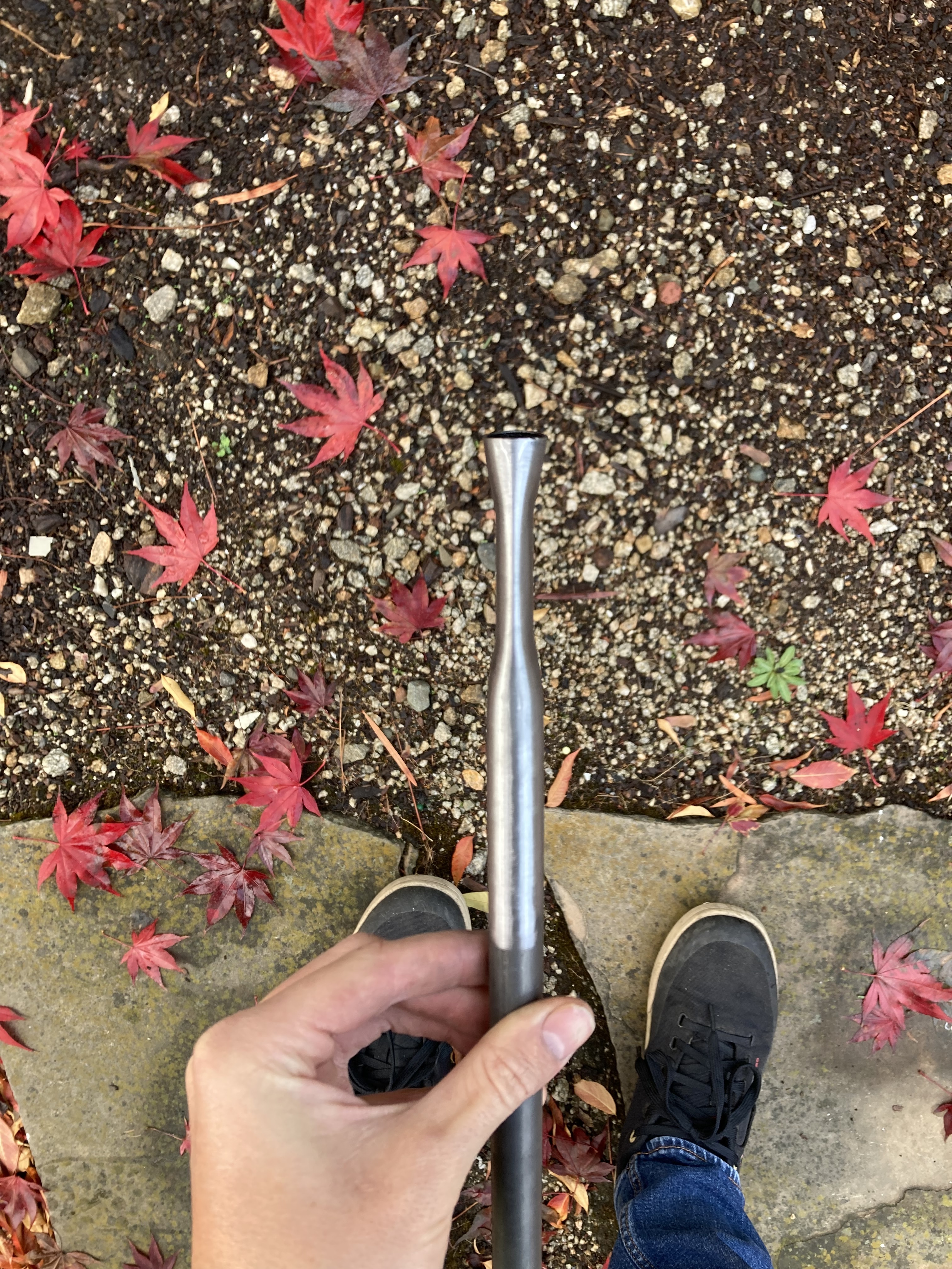
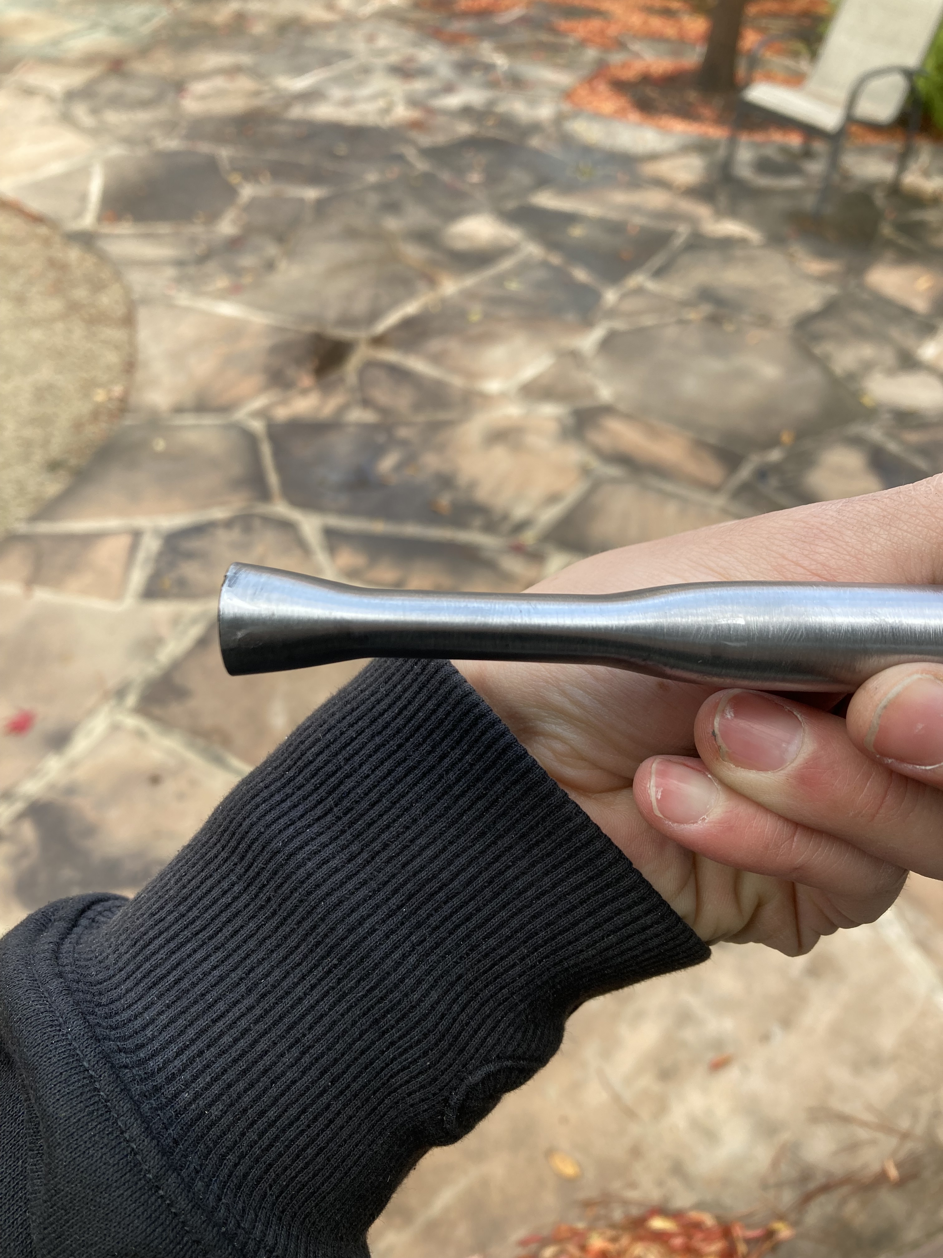
Smooshed tube is shown below. The first attempt worked well - the small imperfections near the end of the tube were present before smooshing; I don’t think the tube sustained noticeable cosmetic damage while pressing.

The final elliptical section is 9.7mmx21.8mm (compared to the 9mmx21.4mm as designed). This lines up well with the assumption that the cross-sectional circumference stays relatively constant throughout the smoosh area (~51.3mm for the ellipse vs 49.9mm for the round section).


Oversights/Learnings

I didn’t add any locating features to align the two dies aside from the oversized bolt holes. I don’t think a lateral (side-side) locating feature is necessary - the two halves seem to self-align while being pressed. I should have added a longitudinal locating feature as the two halves were misaligned by 0.5-1mm during my test. I was originally worried about binding the die closing with an alignment feature; in retrospect, this isn’t a big concern.

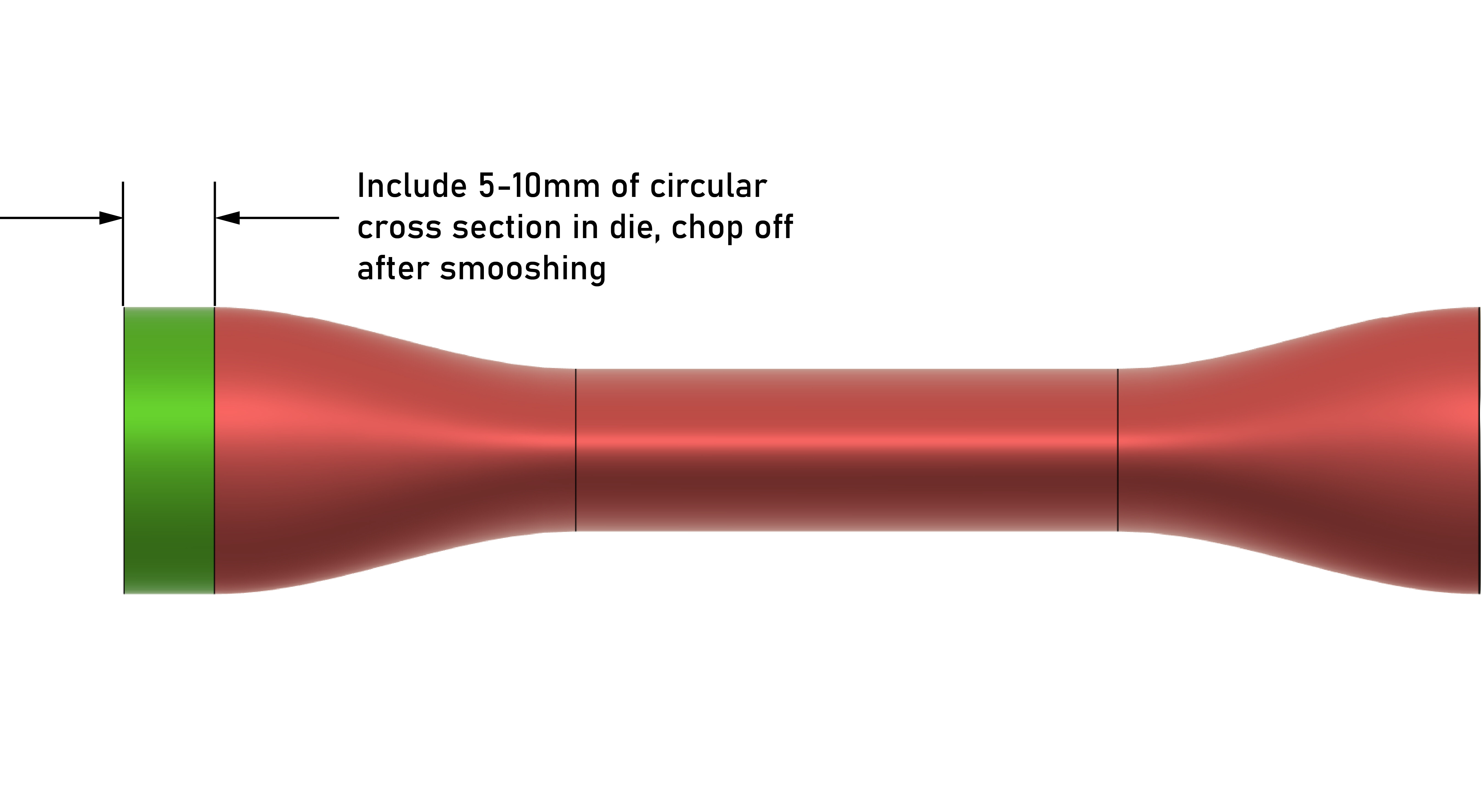
The end of the tube flares out. Not a big problem, and something I can easily fix with a quick file or trip to the mill/lathe. If making the die again, I’d add a 5-10mm long circular entrance section and chop off the end of the tube after smooshing. Unfortunately, I’ve already ordered tubes from PTL cut to final length and can’t implement this change on my current project.

Overall, promising results and I’m eager to build a frame with this method. Fusion 360 file below for those interested.

Ovalizing Press v7.f3d (200.0 KB)

12 Likes